
Description
Precautions:Installation location:This productcan be installed both indoors and outdoors. It is recommended to install it near the smart home control box.Wiring operation:
- The input terminals for different control modes have different wiring terminals. Please select the corresponding interface according to your needs. Please control the cable length of the LAN port within 80 meters.
- Please control the cable length of the LAN port within 80 meters.
- Please carefully read the safety precautions before installation to ensure correct installation.
- Please have dealers or professionals install it, do not install it yourself to avoid electric shock or fire.
- Use the specified accessories and parts to ensure a secure installation.
- Be sure to turn off the power during installation work.
- Do not disassemble, modify or repair this device.
- All lines must be safe, using designated wires to ensure that external forces do not affect the terminal board and wires. Poor contact or improper installation may lead to fire.
- Poor contact or improper installation may lead to fire.
When selecting installation materials, national or international standards must be followed, taking into account earthquake conditions.Power Line:Insufficient capacity or improper installation of power lines may result in electric shock, and residual current circuit breakers must be installed in case of fire.Child safety:Do not allow children to play with this device.Signal line layout:All signal cables should not be routed side by side with power cords and other signal cables, as it may cause interference and misoperation. If parallel wiring is required, the distance between the wiring for communication with the air conditioner should be kept at 15cm, and the distance between the wiring and other wiring should be kept at least 30cm, or an iron protective tube should be used and one end of the protective tube should be grounded. The chassis must be grounded in type D.Power cord connection:In the case of incorrectly connecting the power cord to the signal terminal, the fuse will burn out to protect the printed circuit board. At this time, please contact the manufacturer and it is strictly prohibited to disassemble and repair without authorization.Product maintenance:Unauthorized disassembly and repair of products are strictly prohibited, and the manufacturer does not provide after-sales service.Device version number:ALL/20210304Product List:
- One gateway
- A certificate of conformity
- A product specification sheet
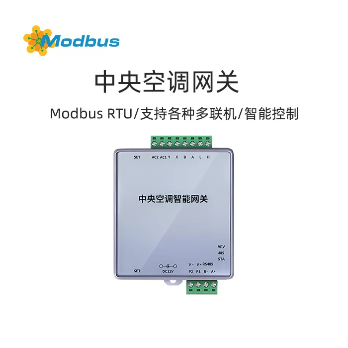
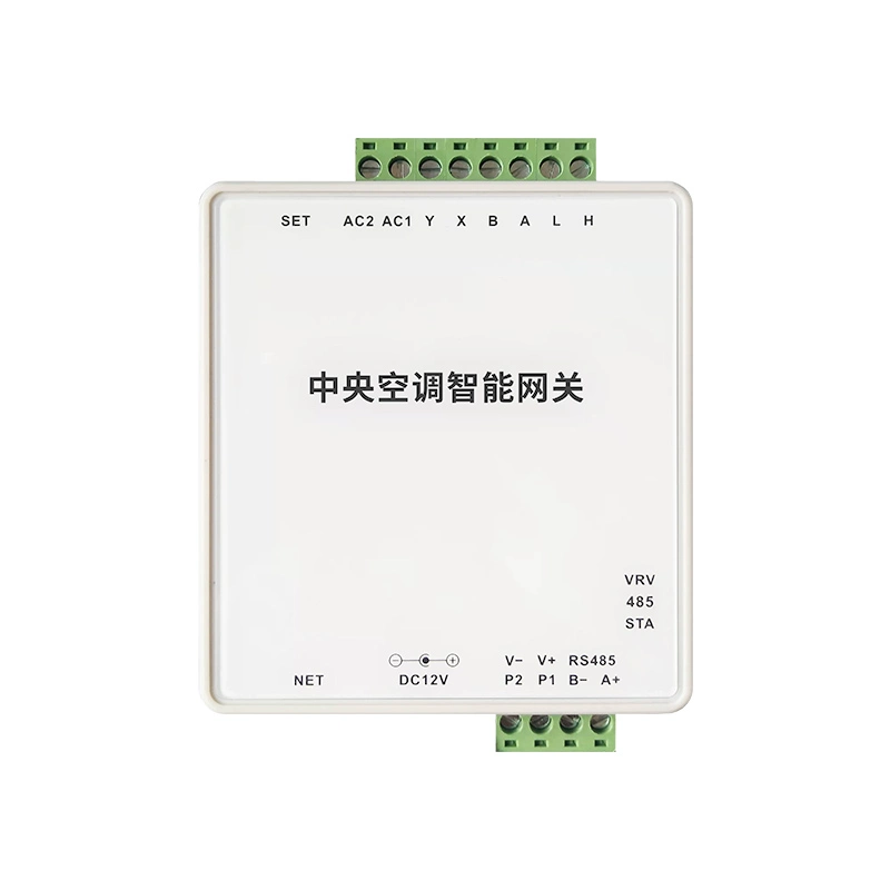
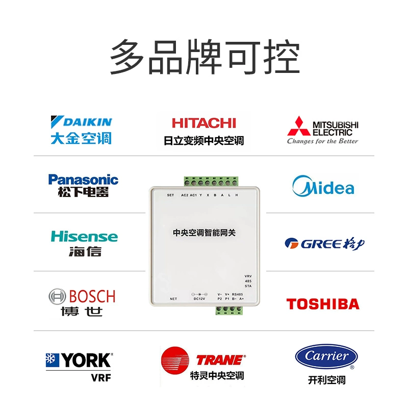
This product is a multi in one gateway that is compatible with multiple brandscentral air conditioningJust needManual dialing codeIt can achieve an intelligent gateway for controlling multiple brands of central air conditioning with one machine. It can connect multi connected air conditioning systems to multiple smart home systems, and third parties can control the on/off, temperature adjustment, mode switching, wind speed adjustment, and other functions of multi connected central air conditioning through the gateway MODBUS protocol.Product Manual:https://www.modbus.cn/30214.html Product Basic Specifications and Electrical Parameters:
- Product Name:Central Air Conditioning Multi in One Intelligent Control Gateway
- Product Model:TDFH-DUX/YC
- Communication interface:RS485/Ethernet port
- Product dimensions:80*87*39mm in lengthWidthHigh)
- Transmission mode:Half-duplex
- Starting and stopping positions:one
- Data bit/check bit:8 No NONE 1
- External interface:RS485 Ethernet port (TCP/IP)
- Power consumption:40mv-300mv, 2/3W
- Power supply:12V-24V
- Baud rate:9600bps
- Installation location:Air conditioning indoor or outdoor unit (Gree, Midea, Songxia are recommended to install on outdoor units, with one gateway installed on each outdoor unit in the case of multiple outdoor units)
- Cable requirements:DATA wiring uses 2-core shielded wire 21.0 or 21.5 (cannot be replaced by Ethernet cable)
The standard product is 485 and the network port wiring method. Wireless products can be customized, and built-in products require the buyer to provide relevant modules.Terminal and Indicator Light Description: The upper 8P terminal of
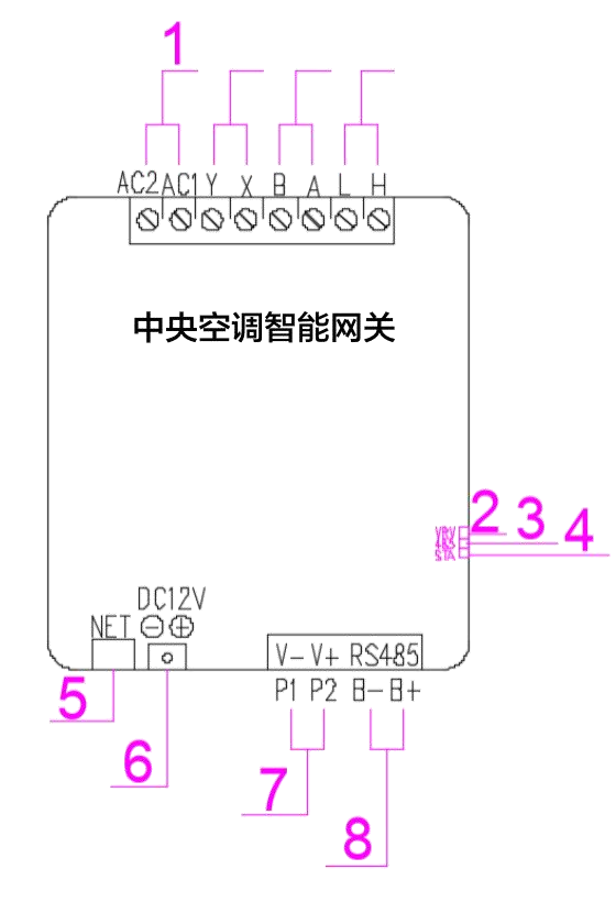
- is the wiring terminal for the air conditioning signal line, as defined in Table 1.
- Indicator light VRV: air conditioning communication terminal block. Constant light indicates standby, while flashing indicates communication between the gateway and the air conditioner.
- indicator light 485: communicates with 485 or Bluetooth. Constant light indicates standby, while flashing indicates communication between the gateway and the host.
- Indicator light STA: Power light. Constant light indicates normal operation, while flashing indicates that the gateway is in working communication.
- NET is the network port terminal.
- DC12V ± power port (plug-in port).
- P1P2 (VV+) is also a power port used for plugging in cables.
- The RS485 port is a wiring port for 485 communication mode.
- Installation conditions:Both indoor and outdoor units are suitable, but Gree, Midea, and Panasonic recommend installing them on outdoor units. In the case of multiple outdoor units, each outdoor unit should be equipped with a gateway.
- Maximum limit for internal and external units:Mitsubishi Electric has a maximum limit of 50 internal units, while other controllable brands have a maximum limit of 64 internal units.
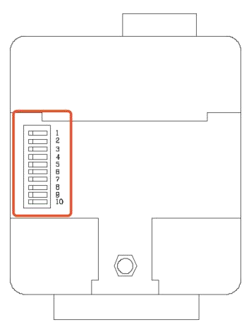
- Dial the code on the back of the gateway to the corresponding air conditioning brand (see Table 1).
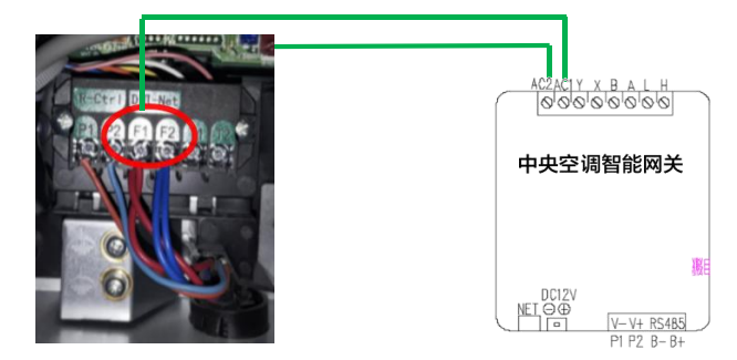
- Connect the corresponding port of the gateway to the corresponding port of the indoor or outdoor unit of the air conditioner (using RVVP2 * 0.75 or above two core shielded wire is required). Specific ports by brand, see Table 1). For example, F1F2 in the red circle of the Daikin central air conditioning unit is connected to the gateway port AC1AC2.
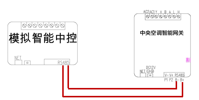
- Connect to the intelligent central control host through the 485 communication port and network port based on the host interface. For example, the central control host has a 485 communication port, and the wiring method is shown in the following figure:
- Gateway P1, P2, and DC12V ± ports can all be powered on (please use a 12-24V power adapter).
- Address code for air conditioning thermostat. Allocation method: Daikin, Toshiba single system, andmulti systemare manually allocated on the original temperature controller. Other controllable brand single systems are automatically assigned addresses after connecting the air conditioning signal line, while multi systems are manually assigned by dialing codes on the internal and external units. Please contact the relevant staff for the specific dialing method of the wall temperature controller. After installation, power off and restart the air conditioner and gateway.
- After installation, power off and restart the air conditioner and gateway.
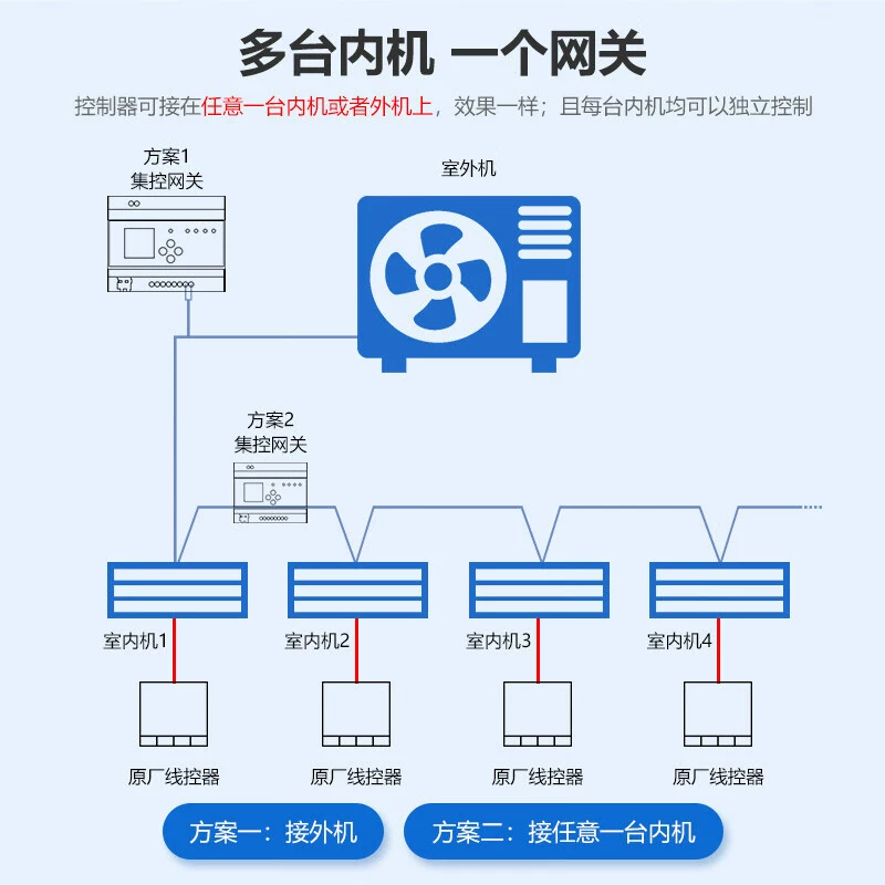
- Single System: Both internal and external units can be connected.
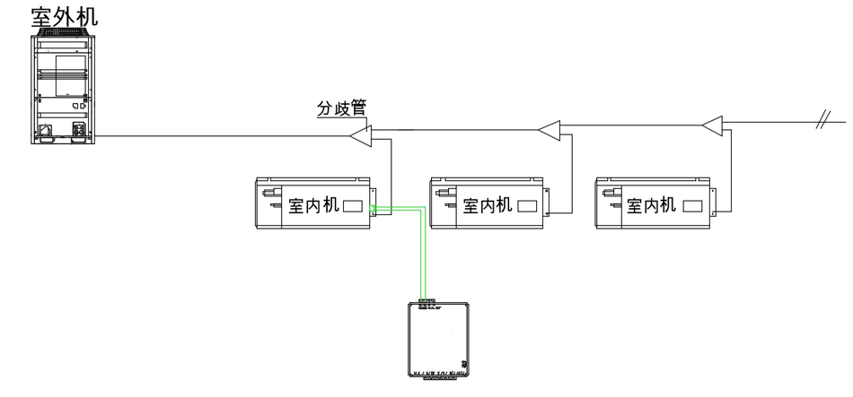
- Multi system: Each brand of outdoor unit is also connected to the corresponding signal port, and the port code remains unchanged. Taking Daikin as an example: The equipment can be installed on both internal and external devices, except for multiple external devices, F1F2 can be connected in series. Installed on any internal unit or external unit.
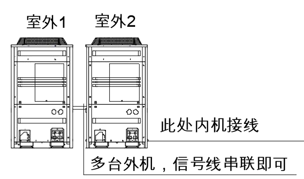
) Advantages: Directly dial the code to the desired brand of air conditioner locally, without the need to download and load relevant brands from the cloud. Before officially using this product, the product dialing and communication line connection should be completed according to the requirements of this section. The access of dialing and communication lines is mainly determined based on the brand of central air conditioning, and detailed requirements are shown in the table below.
Before officially using this product, the product dialing and communication line connection should be completed according to the requirements of this section. The access of dialing and communication lines is mainly determined based on the brand of central air conditioning, and detailed requirements are shown in the table below.Explanation: 0 is OFF and does not need to be dialed; 1 is ON, dial up the code. The factory status is all 0.
Table 1:
Air conditioning brand
Dialing method
Air conditioning signal port
Corresponding gateway wiring port
1. Daikin
00:00 00:00 00:00 00:00 00:00
F1-F2
AC1-AC2
2. Hitachi
00:00 00:00 0001
1-2
AC1-AC2
3. Toshiba
0 1 0 0 0 0 0 0 0 0 0 0
U1-U2
AC1-AC2
4. Mitsubishi Electric
1 1 1 0 0 0 0 0 0 0 0
M1-M2
AC1-AC2
5. Mitsubishi Heavy Industries
0 0 1 0 0 0 0 0 0 0
A-B
A-B
6. Midea
1 0 1 0 0 0 0 0 0
X-Y
A-B
Small part Midea
1 0 0 0 0 0 0 0 0 0 0
P-Q
A-B
7. Single system Gree
0 1 1 0 0 0 0 0 0
D1-D2
H-L
8. Multi system Gree
0 1 1 0 0 0 0 0 0 0 0
G1-G2
H-L
9. Hisense
1 1 1 1 1 0 0 0 0 0 0 1
1-2
AC1-AC2
10. Heavy Industry Haier
0 0 1 0 0 0 0 0 0 0 0 0 0
A-B
A-B
11. Panasonic
1 0 0 1 0 0 0 0 0 0
U1-U2
AC1-AC2
12. Haier
0 1 0 1 0 0 0 0 0 0
P-Q
AC1-AC2
13. Bosch
1 1 0 1 0 0 0 0 0
X-Y
A-B
14. Samsung
0 1 1 1 1 0 0 0 0 0 0
F1-F2
A-B
15. Carrier
0 1 1 1 0 0 0 0 0 0 0
X-Y
A-B
16. Trane
1 1 1 1 0 0 0 0 0
X-Y
A-B
17. York
1 1 1 1 1 1 0 0 0 1
1-2
AC1-AC2
Use dedicated upgrade software to upgrade the gateway. The gateway related fault query software, software upgrade, and firmware optimization package are all provided by our company.
Communication Protocol
Communication Parameters
(I) 485 Communication Parameters
- Baud Rate: 9600bps
- Data Bit: 8
- Stop Bit: 1
- Parity Check Bit: NONE
(II) Function Code
This gateway supports the following function codes. If it receives a function code other than the one in the table, it will provide an abnormal response:
- 0x04 (04): Read Input Register
- 0x06 (06): Preset Single Register
- 0x10 (16): Preset Multiple Register
Function
(1) Monitoring Function
- Running/Stopping StatusReal time monitoring of whether the indoor unit is in operation or stopped.
- operation modeIdentify the current operating mode of the indoor unit, including cooling, heating, air supply, dehumidification, and other modes (depending on the performance of the indoor unit).
- Temperature settingObtain the set temperature value of the indoor unit.
- indoor temperatureRead the actual temperature of the indoor unit's environment.
- suction temperatureMonitor the suction temperature of the indoor unit.
- Air volumeUnderstand the air volume settings of indoor units, such as LL, L, M, H, HH levels (depending on the performance of the indoor unit).
- Forced stop stateDetermine whether the indoor unit is in a forced stop state.
- Exception codeWhen the indoor unit malfunctions or receives a warning, obtain the corresponding exception code.
(2) Control function
- Operation/Stop ControlCan remotely control the start and stop of indoor units.
- Operation mode settingThe operating modes of the indoor unit can be set to cooling, heating, air supply, dehumidification, etc. (depending on the performance of the indoor unit).
- Temperature settingRemote adjustment of the cooling or heating set temperature of the indoor unit.
- Air volume settingModify the air volume settings of the indoor unit, such as LL, L, M, H, HH levels (depending on the performance of the indoor unit).
(3) Retrieval system information function
- communication statusCheck if the communication between the gateway and the indoor unit is normal.
- Indoor unit connection informationObtain the number of connected indoor units and the network address of each indoor unit.
Protocol Content
(1) Read Status
1. Read Adapter Status
- Function Code: 0x04 (04)
- Register Address: 30001 (0x0000)
- Function: Read Adapter Status
- Response Data: 00 (not ready) or 01 (ready)
- Example:
  查询:01 04 00 00 00 01 31 CA
  Response:01 04 02 00 01 78 F0
2. Read the connection status of the indoor unit
- function code: 0x04(04)
- Register address range: 30002 (0x0001) ~ 30005 (0x0004)
- FunctionRead the connection status of indoor units, with each register corresponding to the connection status of 16 indoor units
- response dataThe value of each register is a 16 bit binary number, and each bit represents the connection status of the corresponding indoor unit (0: not connected; 1: connected)
- Example:
  查询:01 04 00 01 00 04 A0 09
  Response:01 04 08 FF FF FF 3F 3F FF 00 00 58 28
3. Check the status of the indoor unit
- function code: 0x04(04)
- Register address range: 32001 (0x07d0) ~ 32384 (0x07e8)
- FunctionQuery the status of a single or multiple indoor units, including air volume, switch, mode, set temperature, fault codes, indoor temperature, temperature sensor status, etc
- Query format: The starting address of the register and the number of registers to be queried need to be specified. The status information of each indoor unit occupies 6 registers, with register addresses starting from 32001 and every 6 registers being the starting address of the next indoor unit.
- Response data parsing:
- Airflow/Wind Direction: The high 4 bits of the register value represent the airflow (0x10=LL, 0x20=L, 0x30=M, 0x40=H, 0x50=HH, 0xA0=Auto), and the low 3 bits represent the wind direction (0-7, 0=horizontal, 4=vertical, 7=swing).
- Switch: The lowest bit of the register value indicates the switch status (1=on, 0=off).
- Mode: The lower 4 bits of the register value indicate the mode (0=air supply, 1=heating, 2=cooling, 7=dehumidification).
- Set temperature: Divide the combination of high and low bytes of the register value by 10 to obtain the set temperature.
- Fault code: The register value corresponds to the fault code, please refer to the fault code mapping table for details.
- Indoor temperature: The combination of the high and low bytes of the register value is divided by 10 to obtain the indoor temperature.
- Temperature sensor status: A register value of 0x0800 indicates normal, while 0x0001 indicates abnormal.
- Example:
  查询:01 04 07 D0 00 06 70 85
  Response:01 04 0C 50 00 42 02 01 18 00 00 01 0A 80 00 F6 FA
4.4 Status Information of Indoor Unit
4.4.1 Adapter Address
| Register Address Range | Indoor Unit Address |
|---|---|
| 32001-32006 | 1-00 |
| 32007-32012 | 1-01 |
| 32013-32018 | 1-02 |
| 32019-32024 | 1-03 |
| 32025-32030 | 1-04 |
| 32031-32036 | 1-05 |
| 32037-32042 | 1-06 |
| 32043-32048 | 1-07 |
| 32049-32054 | 1-08 |
| 32055-32060 | 1-09 |
| 32061-32066 | 1-10 |
| 32067-32072 | 1-11 |
| 32073-32078 | 1-12 |
| 32079-32084 | 1-13 |
| 32085-32090 | 1-14 |
| 32091-32096 | 1-15 |
| 32097-32102 | 2-00 |
| 32103-32108 | 2-01 |
| 32109-32114 | 2-02 |
| 32115-32120 | 2-03 |
| 32121-32126 | 2-04 |
| 32127-32132 | 2-05 |
| 32133-32138 | 2-06 |
| 32139-32144 | 2-07 |
| 32145-32150 | 2-08 |
| 32151-32156 | 2-09 |
| 32157-32162 | 2-10 |
| 32163-32168 | 2-11 |
| 32169-32174 | 2-12 |
| 32175-32180 | 2-13 |
| 32181-32186 | 2-14 |
| 32187-32192 | 2-15 |
| 32193-32198 | 3-00 |
| 32199-32204 | 3-01 |
| 32205-32210 | 3-02 |
| 32211-32216 | 3-03 |
| 32217-32222 | 3-04 |
| 32223-32228 | 3-05 |
| 32229-32234 | 3-06 |
| 32235-32240 | 3-07 |
| 32241-32246 | 3-08 |
| 32247-32252 | 3-09 |
| 32253-32258 | 3-10 |
| 32259-32264 | 3-11 |
| 32265-32270 | 3-12 |
| 32271-32276 | 3-13 |
| 32277-32282 | 3-14 |
| 32283-32288 | 3-15 |
| 32289-32294 | 4-00 |
| 32295-32300 | 4-01 |
| 32301-32306 | 4-02 |
| 32307-32312 | 4-03 |
| 32313-32318 | 4-04 |
| 32319-32324 | 4-05 |
| 32325-32330 | 4-06 |
| 32331-32336 | 4-07 |
| 32337-32342 | 4-08 |
| 32343-32348 | 4-09 |
| 32349-32354 | 4-10 |
| 32355-32360 | 4-11 |
| 32361-32366 | 4-12 |
| 32367-32372 | 4-13 |
| 32373-32378 | 4-14 |
| 32379-32384 | 4-15 |
4.5 Preset Single Register
4.5.1 Adapter Address
| Register Address Range | Indoor unit address |
|---|---|
| 40001-40003 | 1-00 |
| 40004-40006 | 1-01 |
| 40007-40009 | 1-02 |
| 40010-40012 | 1-03 |
| 40013-40015 | 1-04 |
| 40016-40018 | 1-05 |
| 40019-40021 | 1-06 |
| 40022-40024 | 1-07 |
| 40025-40027 | 1-08 |
| 40028-40030 | 1-09 |
| 40031-40033 | 1-10 |
| 40034-40036 | 1-11 |
| 40037-40039 | 1-12 |
| 40040-40042 | 1-13 |
| 40043-40045 | 1-14 |
| 40046-40048 | 1-15 |
| 40049-40051 | 2-00 |
| 40052-40054 | 2-01 |
| 40055-40057 | 2-02 |
| 40058-40060 | 2-03 |
| 40061-40063 | 2-04 |
| 40064-40066 | 2-05 |
| 40067-40069 | 2-06 |
| 40070-40072 | 2-07 |
| 40073-40075 | 2-08 |
| 40076-40078 | 2-09 |
| 40079-40081 | 2-10 |
| 40082-40084 | 2-11 |
| 40085-40087 | 2-12 |
| 40088-40090 | 2-13 |
| 40091-40093 | 2-14 |
| 40094-40096 | 2-15 |
| 40097-40099 | 3-00 |
| 40100-40102 | 3-01 |
| 40103-40105 | 3-02 |
| 40106-40108 | 3-03 |
| 40109-40111 | 3-04 |
| 40112-40114 | 3-05 |
| 40115-40117 | 3-06 |
| 40118-40120 | 3-07 |
| 40121-40123 | 3-08 |
| 40124-40126 | 3-09 |
| 40127-40129 | 3-10 |
| 40130-40132 | 3-11 |
| 40133-40135 | 3-12 |
| 40136-40138 | 3-13 |
| 40139-40141 | 3-14 |
| 40142-40144 | 3-15 |
| 40145-40147 | 4-00 |
| 40148-40150 | 4-01 |
| 40151-40153 | 4-02 |
| 40154-40156 | 4-03 |
| 40157-40159 | 4-04 |
| 40160-40162 | 4-05 |
| 40163-40165 | 4-06 |
| 40166-40168 | 4-07 |
| 40169-40171 | 4-08 |
| 40172-40174 | 4-09 |
| 40175-40177 | 4-10 |
| 40178-40180 | 4-11 |
| 40181-40183 | 4-12 |
| 40184-40186 | 4-13 |
| 40187-40189 | 4-14 |
| 40190-40192 | 4-15 |
(2) Control function
1. Switch and wind speed setting
- function code: 0x06(06)
- Register address range: 42001 (0x07d0) ~ 42192 (0x07e8)
- FunctionControl the switch status and wind speed setting of indoor units
- Write data format:
- Wind speed: The top 4 digits represent wind speed (0x10=LL, 0x20=L, 0x30=M, 0x40=H, 0x50=HH, 0xA0=automatic)
- Wind direction: The lower 3 digits indicate the wind direction (0-7, 0=horizontal direction, 4=vertical direction, 7=swing wind)
- Switch: Single byte, 60=shutdown, 61=startup
- Example:
  查询:01 06 07 D0 10 60 84 AF
  Response:01 06 07 D0 10 60 84 AF
2. Mode setting
- function code: 0x06(06)
- Register address range: 42001 (0x07d0) ~ 42192 (0x07e8)
- FunctionSet the operating mode of the indoor unit
- Write data format:
- Mode: 00 00=ventilation mode, 00 01=heating mode, 00 02=cooling mode, 00 07=dehumidification mode, 00 03=automatic mode
- Example:
  查询:01 06 07 D4 00 02 49 47
  Response:01 06 07 D4 00 02 49 47
3.Temperature Setting
- Function Code: 0x006 (06)
- Register Address Range: 42001 (0x07d0)~42192 (0x07e8)
- Function: Set the cooling or heating temperature of the indoor unit
- Write Data Format:
- Temperature: The combination of high and low bytes represents the temperature. Values, such as 00 A0 representing 16 degrees Celsius, 00 AA representing 17 degrees Celsius, etc
- Example:
  查询:01 06 07 D2 00 A0 28 FF
  Response:01 06 07 D2 00 A0 28 FF
(3) Other functions
1. Control indoor unit
- function code: 0x10(16)
- Register address range: 42001 (0x07d0) ~ 42192 (0x07e8)
- FunctionWrite multiple control parameters to the indoor unit at once
- Write data format:
- The control information of each indoor unit occupies three registers, which are used to store switch, wind speed, mode, temperature and other information
- Example:
  查询:01 10 07 D9 00 03 06 10 60 00 02 00 A0 C2 A5
  Response:01 10 07 D9 00 03 50 87
- 01: Slave address, indicating the need to communicate with the slave device with address 01.
- 10: Function code, indicating that the operation to be executed is to preset multiple registers.
- 07 D9: Register address, indicating that the starting register address for writing data is 07 D9 (hexadecimal), corresponding to the control register of the fourth indoor unit of the air conditioner.
- 00 03: Number of registers, indicating that there are three registers to be written with data.
- 06: Byte length, indicating a total of 6 bytes of data to be written.
- 10 60 00 02 00 A0: The written data sequentially represents control information such as wind speed, switch, mode, temperature, etc.
- C2 A5: CRC checksum, used to ensure the integrity of data transmission.
Data Analysis
- Wind speed and switch control:
10 60- Wind speed: high by 4 digits
10The wind speed is LL (low speed). - Switch: Low 4 bits
60Indicates a shutdown operation.
- Wind speed: high by 4 digits
- Mode setting:
00 02- Mode value
02Set to cooling mode.
- Mode value
- Temperature setting:
00 A0- Temperature value
A0Set the temperature to 16 degrees Celsius.
- Temperature value
2. Query/Set Air Conditioning Type
- function code: 0x05
- register address: 00 00 (query default value) or 00 01 (set value)
- Function: Query or set air conditioning type
- Query format:
  查询:01 05 00 00 00 00 CD CA
  Response:01 05 00 00 01 00 CC 5A
- Set Format:
  查询:01 05 00 01 01 00 9D DA
  Response:01 05 00 01 01 00 9D DA
3. Modify the slave address
- function code: 0x06(06)
- register address: AA
- Function: Modify slave address
- Write data format:
- New Address: One byte representing the new slave address
- ExampleChange the slave address to 03:
  查询:01 06 AA 03 DF 78
  Response:01 06 AA 03 DF 78
2, Appendix
(1) Daikin Exception Code Mapping Table
| Value 2 | Code | Value 1 | Code |
|---|---|---|---|
| 0 | 0 | 0 | 0 |
| 1 | A | 1 | 1 |
| 2 | C | 2 | 2 |
| 3 | E | 3 | 3 |
| 4 | H | 4 | 4 |
| 5 | F | 5 | 5 |
| 6 | J | 6 | 6 |
| 7 | L | 7 | 7 |
| 8 | P | 8 | 8 |
| 9 | U | 9 | 9 |
| 10 | 9 | 10 | A |
| 11 | 8 | 11 | H |
| 12 | 7 | 12 | C |
| 13 | 6 | 13 | J |
| 14 | 5 | 14 | E |
| 15 | 4 | 15 | F |
| 16 | 3 | ||
| 17 | 2 | ||
| 18 | 1 | ||
| 19 | G | ||
| 20 | K | ||
| 21 | M | ||
| 22 | N | ||
| 23 | R | ||
| 24 | T | ||
| 25 | V | ||
| 26 | W | ||
| 27 | X | ||
| 28 | Y | ||
| 29 | Z | ||
| 30 | * | ||
| 31 |
Value 1=4, value 2=9, exception code=U4.
(2) Hitachi Exception Code Mapping Table
| Code | Fault Description | Code | Fault Description |
|---|---|---|---|
| 01 | Action of indoor unit protection device | 31 | Abnormal combination of indoor and outdoor unit capacity |
| 02 | Action of outdoor unit protection device (outdoor unit fan protection tripped) | 32 | Normal internal machine disconnection |
| 03 | communication failure | 35 | Duplicate external or internal machine numbers |
| 36 | Internal and external machine models do not match | ||
| 04 | Communication between external motherboard and frequency converter board | Communication between the external motherboard and the fan frequency conversion board | |
| 05 | Power phase sequence | 38 | Outdoor unit protection circuit action |
| 06 | Power module undervoltage (indoor unit voltage too low, commercial split) | Fan control module voltage abnormality | |
| 39 | Constant speed compressor overcurrent or zero current | ||
| 07 | Low exhaust superheat | 3a | Outdoor unit capacity error |
| 08 | High temperature at the top of the compressor | 3b | The combination of outdoor unit and sub unit is incorrect, and the power setting is incorrect |
| 09 | Outdoor fan built-in temperature sensing detection temperature too high | 3d | Communication abnormality between outdoor unit host and sub unit |
| 0A | Abnormal communication between outdoor unit modules | 41 | Refrigeration overload protection |
| 0b | Outdoor unit submodule setting error | 42 | Heating Overload Protection |
| 0c | Outdoor Unit Main Module Setting Error | 43 | Low Pressure Ratio |
| 0d | Abnormal Water Temperature (Water Heat Source) | 44 | Low Pressure Too High |
| 11 | Ti Temperature Sensor Open or Short Circuit | 45 | High Exhaust Pressure |
| 12 | To Temperature Sensor Open or Short Circuit | 46 | Low Exhaust Pressure |
| 13 | Tl Temperature Sensor Open or Short Circuit | 47 | Low pressure |
| 14 | Tg temperature sensor open or short circuit | 48 | Inverter overcurrent protection action |
| 15 | Ta environmental temperature sensor abnormal (total heat exchanger) | 51 | Compressor inverter detects zero current |
| 16 | New air remote transmission temperature sensor open or short circuit | 52 | Compressor inverter detects overcurrent |
| 17 | Line controller built-in sensor abnormal | 53 | Compressor inverter detects abnormality |
| 18 | Indoor fan motor temperature sensor abnormal | 54 | Compressor inverter temperature sensing overheating |
| 19 | Indoor fan motor protection device action | 55 | Inverter not working |
| 20 | Abnormal temperature sensing at the top of the compressor | 56 | Abnormal fan position detection |
| 21 | Abnormal high voltage sensor | 57 | Fan control substrate protection action |
| 22 | Abnormal external air temperature sensing | 58 | Fan control abnormal |
| 23 | Abnormal temperature sensing at the top of the compressor | 59 | Abnormal current of the outdoor unit fan chopper |
| 24 | Abnormal temperature sensing of the cooler | 5a | Fan control substrate temperature rise protection |
| 25 | Abnormal temperature sensing of the cooler | 5b | Fan control board overcurrent protection |
| 29 | Low pressure sensor abnormality | 5c | Fan control board current sensor abnormal |
| 2A | Abnormal water temperature sensor (water heat source) | 96 | KPI room temperature sensor abnormal (FSN) |
| 30 | Wiring Error (FSN) | CH | Device connection error (FSXNQ) |
| EE | Compressor protection |