

Description
Function Description:
A network to 485 gateway device with Modbus edge gateway function, which can poll and temporarily store numerous device register values. At the same time, it can use register value generation and logical judgment function to output custom data to control local devices.
Selection suggestion:
Widely applicable to users who use Modbus devices in homes, office buildings, hotels, banks, hospitals, schools, airports, museums, factories, laboratories, etc., as well as professionals such as weak current integrators and smart home solution engineers.
Product features:
1. It has all the functions of traditional network TCP/IP to 485 conversion.
2, 2 independentserial ports(baud rate can be modified), each independent serial port supports 2 network ports.
3. Each network port can be configured with a server client, heartbeat, and registration package.
4. Four network ports support up to 128 client connections.
5. Network module modifier searches for configuration IP and webpage configuration parameters.
6, Support polling and storing the status of multiple Modbus devices, allowing the server to query and retrieve them all at once.
7. Polling registers support up to 400.
8. Supports multiple conditions and logic, or logical edge judgment, directly executed locally.
9. Edge judgment execution, multiple execution instructions or scene instructions can be added.
10. The execution instruction supports custom data and can drive any bus device.
11. edge computing judgment logic supports up to 256 groups.
12. Supports secondary call development and provides API call interfaces.
13. It has NTP clock timing function, and can issue timing protocol through serial port 1 and 2 when connected to the Internet.
14. The module is compact and supports 35 rail installation, with a wide voltage range of 7-24V power supply.
15. Support sending custom bus data to any serial port through HTTP protocol.
16. The main port supports Modbus TCP 502 port communication to obtain data.
17. Support one-time read from 1-15 registers.
Usage:
1. The module is powered on and connected to the network.
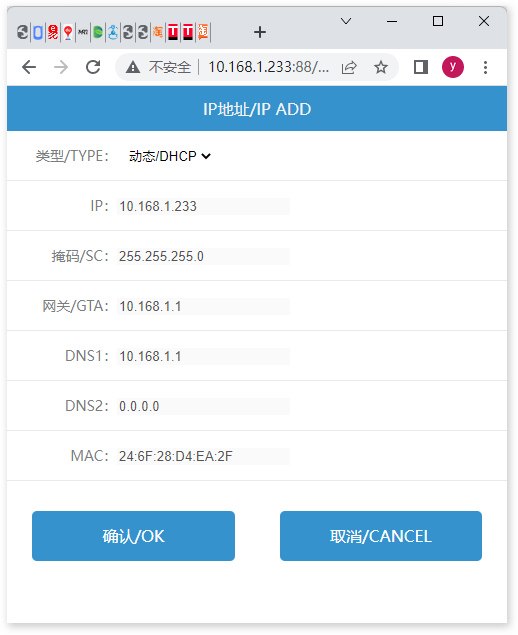
2. Under the same local area network, use the network module modifier to search for IP addresses. The initial state of the module is to automatically obtain IP addresses, and this software is only used for searching, modifying, obtaining IP addresses, and device restarts.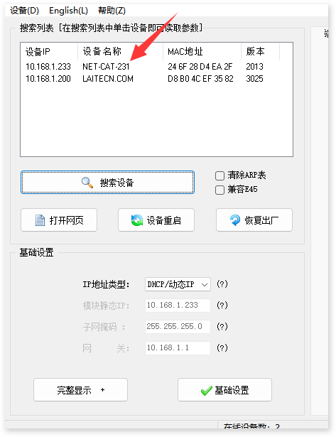
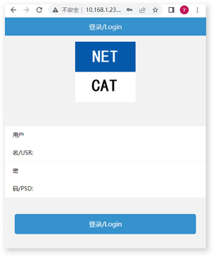
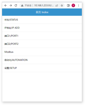
4. The status page displays the status information of the module.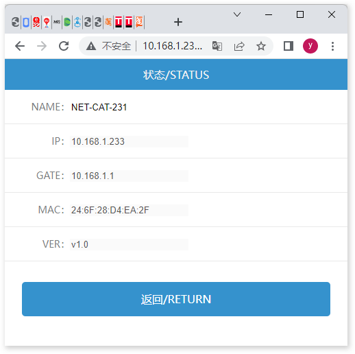
Port 2 user polls the serial port and its corresponding 2 network port configurations.
S/PORT1, The port number corresponding to network port 1;
S/PORT2, corresponding to the port number of network port 2;
RATE is the baud rate; RE CNT, 10 seconds of disconnection and reconnection time;
C1 TYPE port type, server or client;
If client C1 IP is selected, it is the IP address for connecting to the server;
If the client C1 PORT is selected, it is the port for connecting to the server;
If client C1 REG is selected, it is the registration package for connecting to the server, in hexadecimal format;
If client C1 HBC is selected, it is the heartbeat packet for connecting to the server, in hexadecimal format;
If client C1 HBCT is selected, the interval between heartbeat packets connected to the server is in seconds;
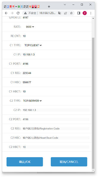
The configuration of S/PORT2 is the same as port 1.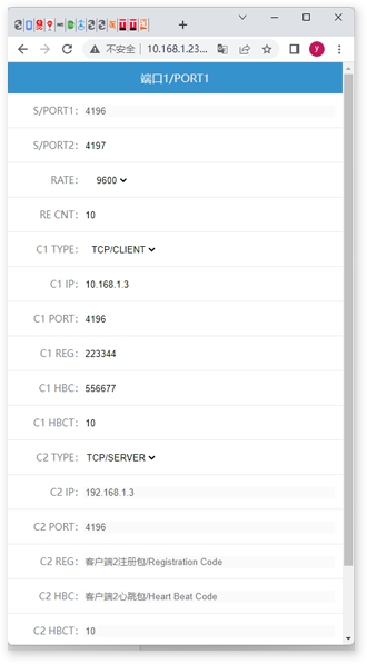
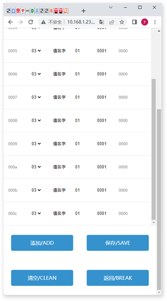
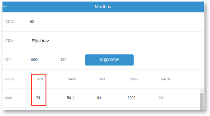
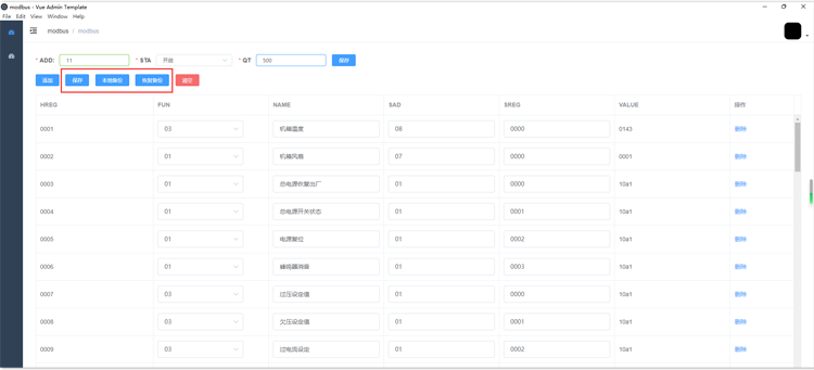
• ADD is the external Modbus address, and you can poll all the register data you have configured through the network and main serial port.
• STA is in status, whether to enable polling.
• QT is the polling time interval between two registers.
• HREG is the Host Register, which can poll the values of the configured registers at once through the network and main serial port.
• FUN represents the polling function code and the number of polling registers. "23" indicates that function code 03 is used to poll 2 registers at once
• NAME is the auxiliary memory for the name of this register.
• SAD stands for Sliver Add, the slave address.
• SREG is the Sliver Register, a slave register.
• VALUE is the value of the polling return register.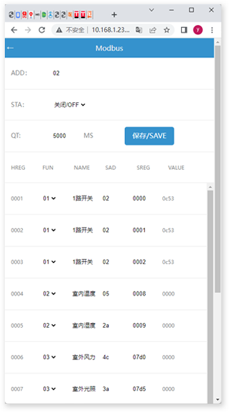
• Automation Name: is the name of this logic.
• Logical operator: You can choose between AND logic (execute only when both are satisfied) and OR logic (execute only when one is satisfied).
• Result True Execution: Indicates that the custom hexadecimal data 1111 (with no spaces between data) is issued after the operation conditions are met. If multiple instructions need to be sent, click Add Execution. The registers involved in logical operations will make a logical judgment whenever one of them changes.
• False execution result: Indicates that the custom hexadecimal data 1111 (with no spaces between data) is issued after the operation conditions are not met. If multiple instructions need to be sent, click "Add Execution". The registers involved in logical operations will make a logical judgment whenever one of them changes.
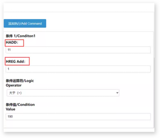
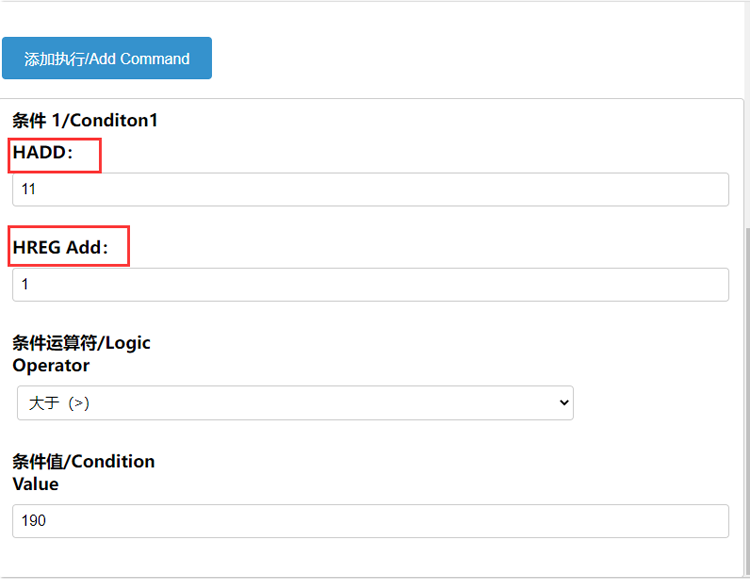
• Condition 1-HADD: Represents the Modbus host address (address of MG02) involved in logical judgment; Condition 1-HREG Add: represents the Modbus host register address involved in logical judgment; In this way, a unique comparison value can be obtained to participate in automated logical operations. Conditional operators represent logical judgment rules for register values, including greater than, less than, equal to, greater than or equal to, less than or equal to, and not equal to; The condition value represents the reference value for participating in the operation rule.
• Add Condition Button: Multiple judgment conditions can be added, combined with logical operators for AND/OR logical judgment.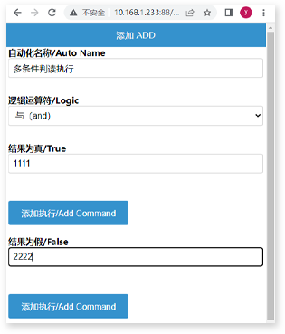
• Whether to enable the timing function, it is possible to send the timing protocol to serial port 1 or serial port 2 through the protocol. The timing cycle is 24 hours, and clicking 'calibrate now' will immediately send the timing protocol. The machine code is the first 4 bytes of the timing protocol.
• Timing Protocol:
Example: Saturday, July 2, 2023 11:27:09:22 10:11 (machine code) F0 BB 78 01 (fixed byte) 0B (11:00) 1B (27 minutes) 09 (09 seconds) 17 (23 years) 07 (July) 02 (2nd) 06 (Saturday) 64 (end byte)
Note: Sunday is 07, not 00
• Issuing port, you can choose the serial port sent by the timing protocol, PORT1 is serial port 1, PORT2 is serial port 2.
• WEB PORT is the web access port, which defaults to 88 and cannot be modified temporarily.
• Module name, for easy management of module names.
Update Function
1. Some devices' register data, especially for electric meter products, is 4 bytes long, so our original storage location of 2 bytes cannot meet it. This optimization supports register data reading with lengths of 2, 4, 5, and 8 bytes. After data reading, it will be automatically recorded in the next data storage location. For example, if your data is 4 bytes and the register address you read is 00 48, then the data will be automatically filled into the host registers 00 11 and 00 12 positions. Register 00 12 is filled with FF 01. This way, the system will automatically skip the 00 12 polling and only poll 00 48 at the 00 11 position. If the first byte of the register address is FF XX, the system will skip polling at that position.
If the first byte of the register address is FF XX, the system will skip polling at that position.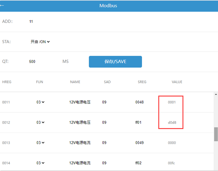
HTTP protocol
supports sending custom serial port data to the bus network through the HTTP protocol. The HTTP protocol format is as follows:
The HTTP protocol format is as follows:
Modbus TCP protocol
Supports Modbus TCP communication method, the usage method is as follows:
In client or server mode, setting the main port to 502 will automatically switch the communication mode between the upper computer and MG02 to Modbus TCP, while the other communication port will become invalid.


