
VisualTFT Software Installation
Visual TFT is a powerful serial port screen development and debugging software independently developed by our company, featuring the first "virtual serial port screen" in China.
Operating Environment: Windows
Download Link: VisualTFT
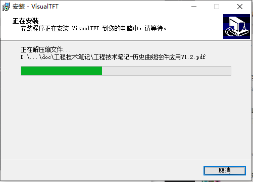
Follow the prompts to select the installation directory, and click "next" step by step to complete the installation. The installation process is as follows
Introduction to VisualTFT Work Interface
If VisualTFT has been successfully installed, open an existing factory project to proceed to the introduction of the VisualTFT work interface. The interface display is as follows
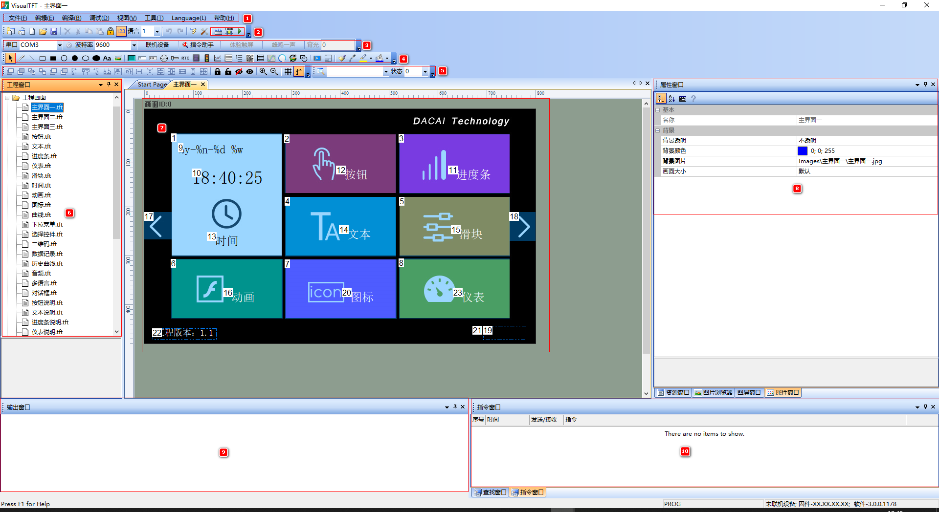
① Menu Bar Area
The main configurations are mainly debugging and tools
Debugging
For serial port debugging, when the physical screen does not support the large color protocol, online operation will fail. At this time, clicking "Debug" → "Online without handshake" in the menu bar allows you to view the interaction of serial port commands in the [Command Window]
Tools
Common operations on the toolbar include:
- Icon generation: generation of icon files
- Font configuration: generation of vector fonts
- Keyboard configuration: customization of user keyboard styles
- Protocol and variables: configuration of modbus/fx2n/xgus protocols
- Minic script programming: after enabling modbus/fx2n/xgus protocols, editable logic lightweight scripts can be created
- Lua script editing: application of Lua scripts for powerful uses such as computation and private serial port protocols
② Compilation area
The editing area mainly includes compilation, download, virtual screen, etc.
- Compiling: You can view the editing results and the used space size in the [Output Window]
- Download: basic type, clicking download will download through the miniusb port, while other series will pop up a mass production download interface, allowing selection of serial port or SD/U disk download
- Run virtual screen: clicking on the configured page will simulate the operation logic of the physical screen
③ Control Area
If the current entity screen adheres to the Large Color protocol, you can select the corresponding serial port number and click to connect. As shown below
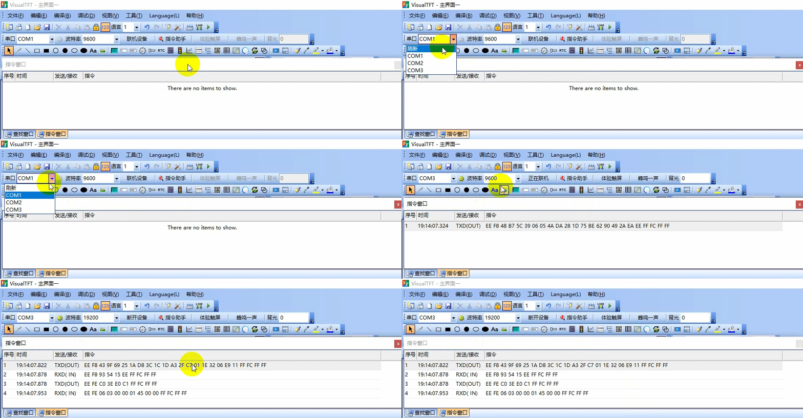
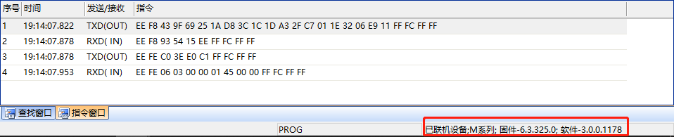
After successful connection, "Connected Devices..." will be displayed in the lower right corner of VisualTFT, indicating that control can be debugged through [Command Debugging]
④ Widget Area
Widgets are primarily divided into basic widgets and configuration widgets
Basic widgets are as follows: brush, line segment, rectangular box, solid rectangle, circle, solid circle, ellipse, solid ellipse, static text, image, etc.

Configuration widgets are as follows, in order: button, text, gauge, slider, RTC, animation, icon, curve, menu, sliding selection, QR code, data logging, historical curve, circular progress bar, basic graphics, video, sub-screen window widget, etc.

⑤ Widget Layout
Used for adjusting the distribution of widgets such as stacking, alignment, spacing, equal width and height, as well as locking, hiding, zooming in and out during the screen layout process

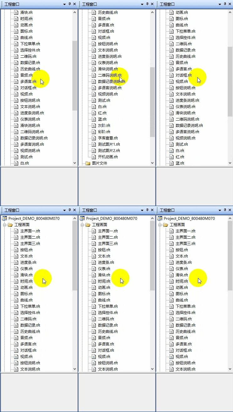
⑥ Project Window
Used to view the created screens and loaded image, audio, video, and other file lists
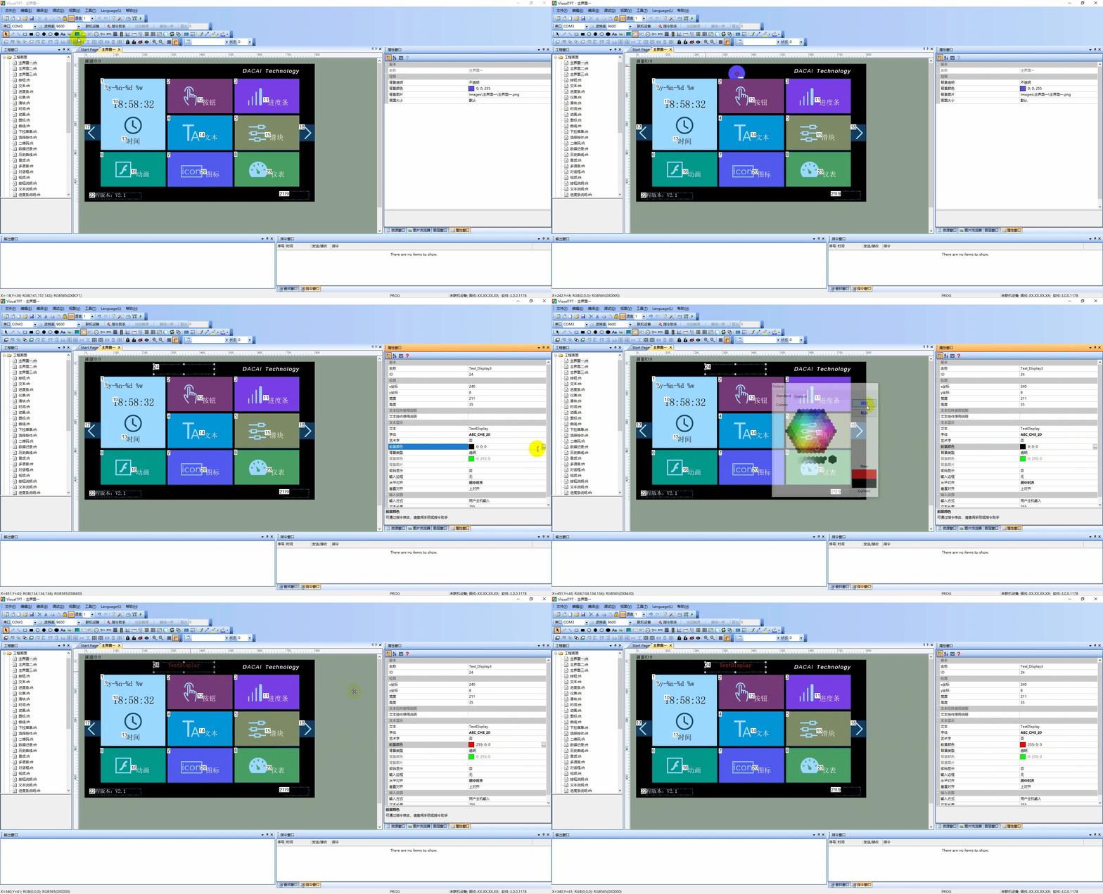
⑦ Editing Area
Mainly responsible for editing the UI interface, the main operational area in development allows users to click and select the desired controls, placing them in this area to complete the creation of controls. Specific operations are as follows:
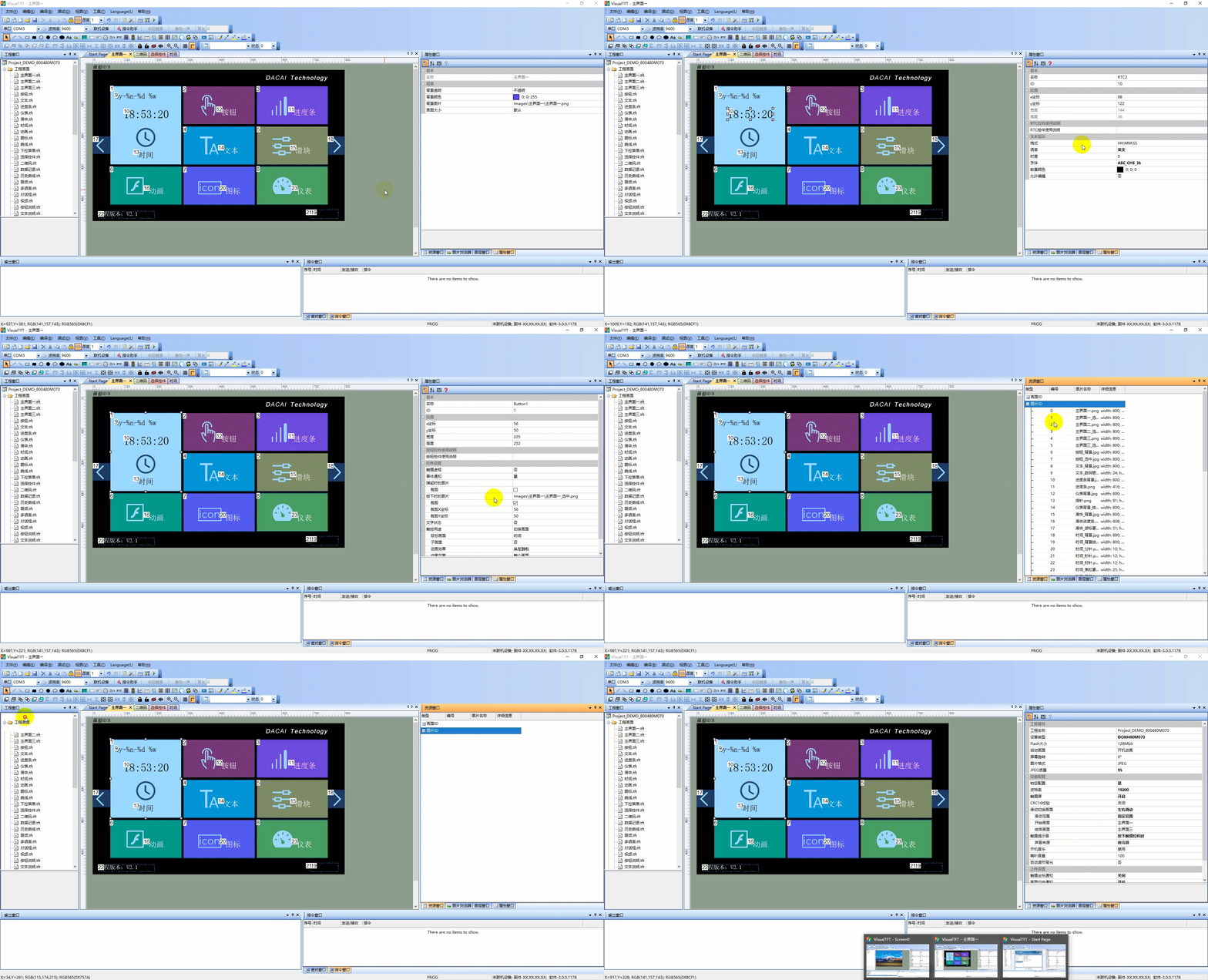
⑧ Property Window
The right side belongs to the Property Window, which mainly allows users to view the overall project configuration properties, control properties, and all screen and image resource windows. As shown below:
⑨ Output Window
When users compile, all errors, warnings, and total project size are output in this window.
⑩ Command Window
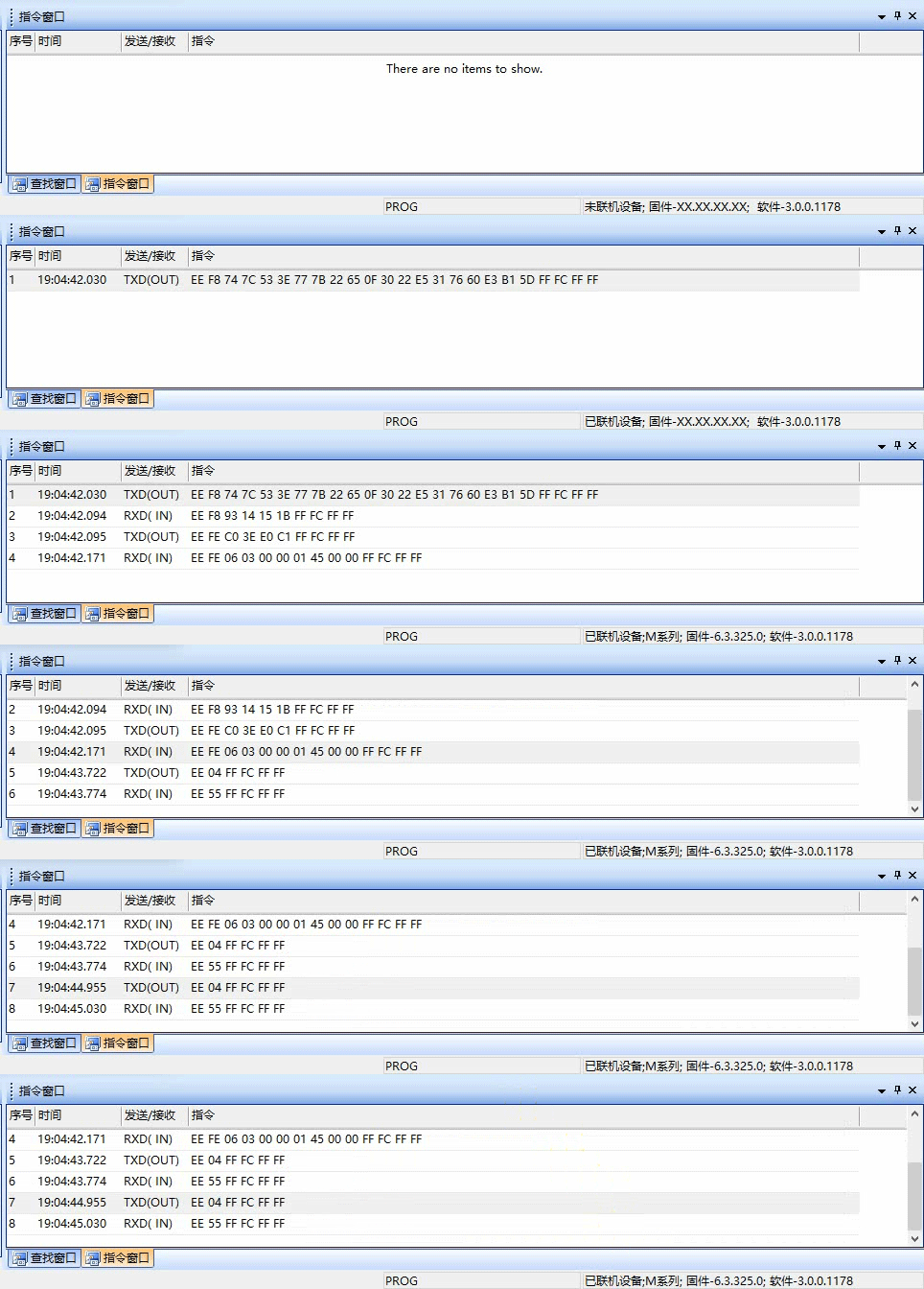
After successfully connecting online, users can view specific message information in the [Command Window] through command sending and receiving control. For example, for the VisualTFT online physical screen, click [Command Assistant] ⇨ Device Handshake
VisualTFT 发送:EE 04 FF FC FF FF
屏幕反馈: EE 55 FF FC FF FF
How to create a project
After understanding the basic VisualTFT interface, this section will create a new project
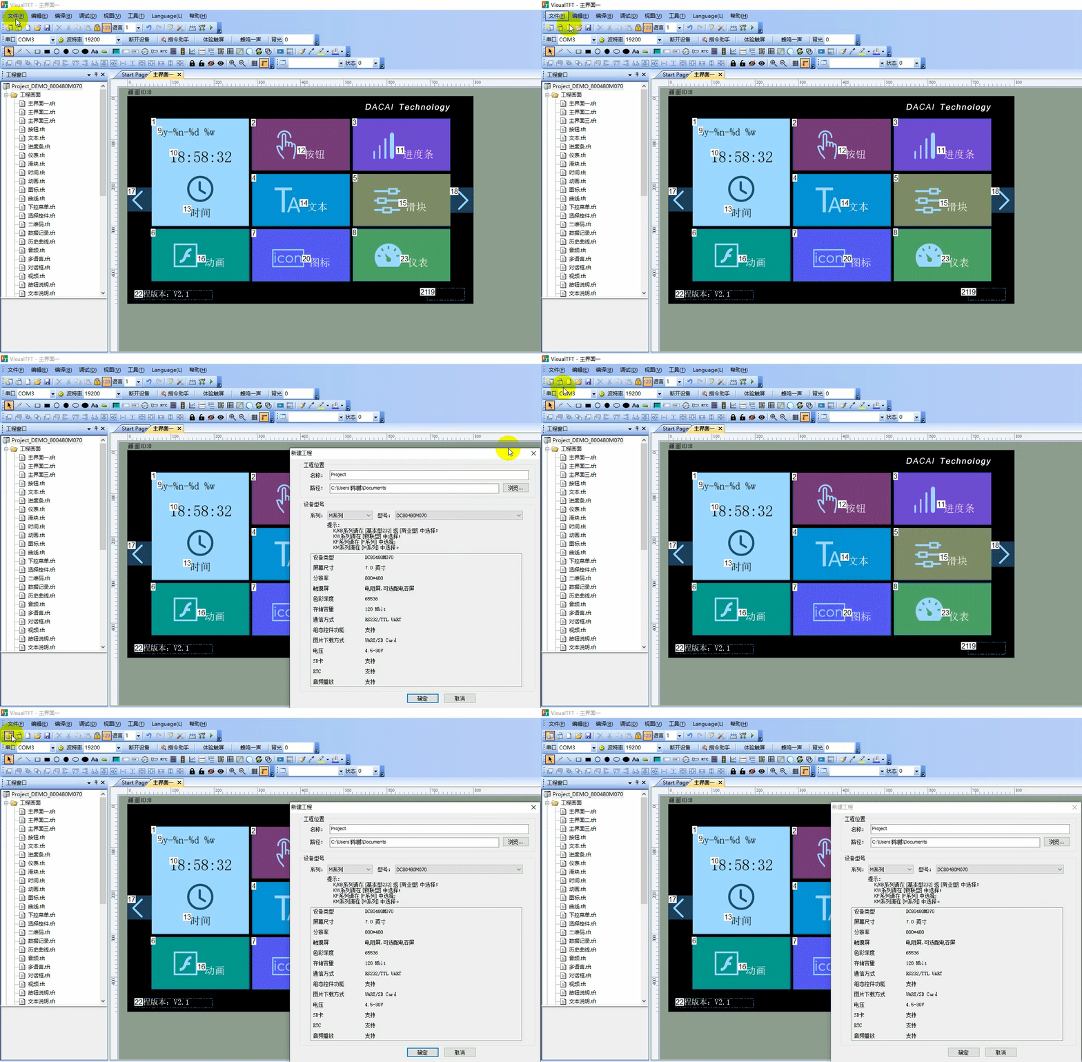
In the menu bar, select "File" ⇨ "New Project N…" in sequence, or directly click the shortcut button to create a new project, as shown below
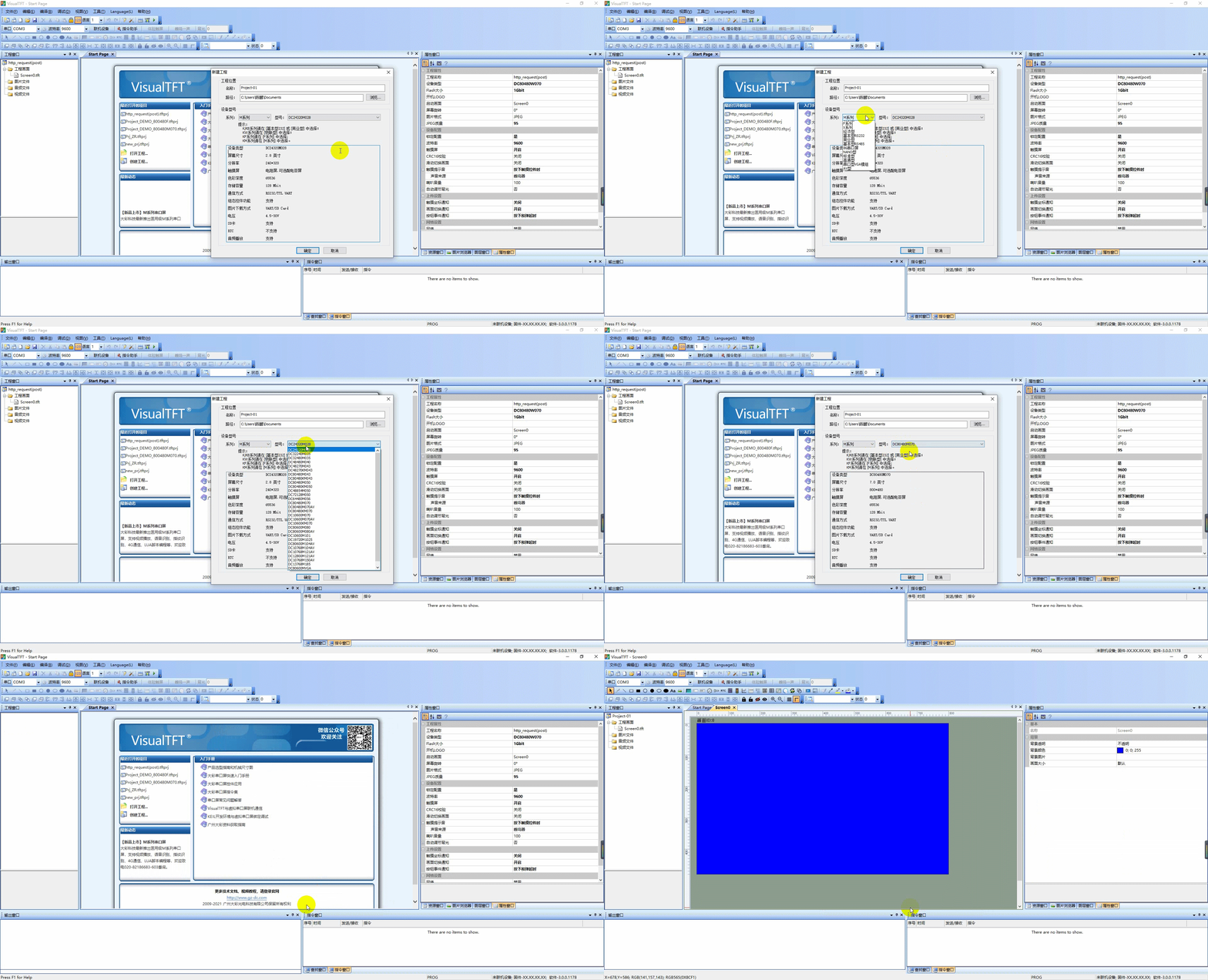
Select the storage path, and according to the physical screen, choose the corresponding resolution and size. For example, if the physical screen model is DC80480M070_1111_0C, the operation is as follows:
How to download a project
M series
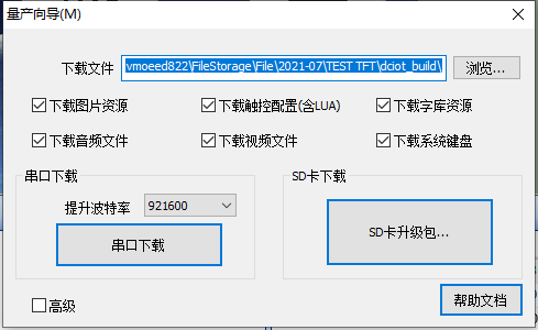
Click the "Compile" button . After successful compilation, the "Mass Production Wizard M" window will automatically pop up. The operation is as follows
Method 1
Serial Port Download: After successful connection, click "Serial Port Download", as shown below
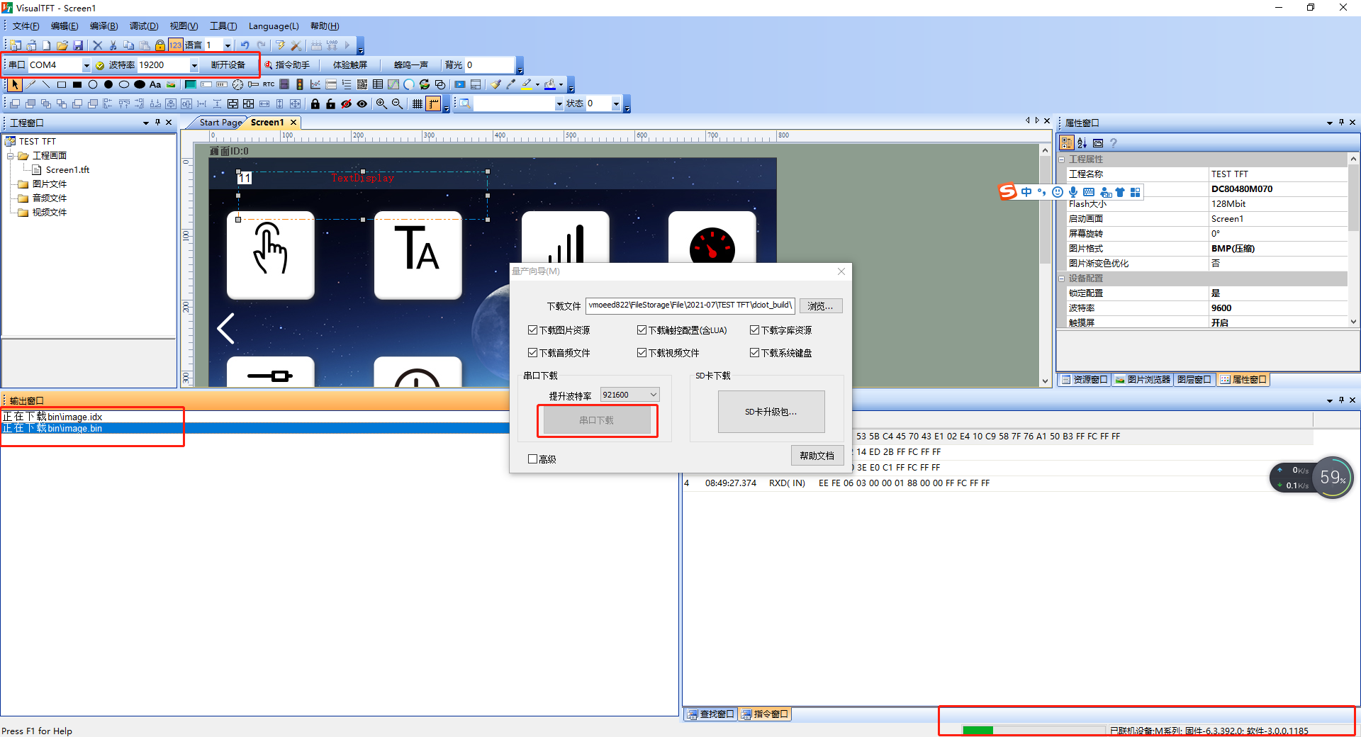
Method 2: SD Card Download
SD Card Requirements
- It is recommended to use a Kingston SD card
- with a capacity of less than or equal to 8G
- and formatted as FAT32
. The upgrade steps are as follows:
① Click "SD Upgrade Package" to automatically pop up the "SD_PACKET" directory
② Copy the files in the directory to the root directory of the SD card
③ Power off the screen
④ Insert the SD card into the SD card slot of the serial port screen
⑤ Power on the screen, and it will automatically enter the download page
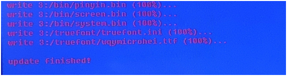
⑥ After the download is complete, the screen will display 'update finished', and the project page will be automatically loaded. Remove the SD card
F series
ClickCompile the project. After successful compilation, the "Mass Production Wizard F" window will automatically pop up. The operation steps are as follows:
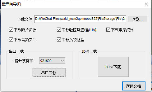
Method 1: Serial port download
After successful connection, click on "Serial Port Download" as shown below
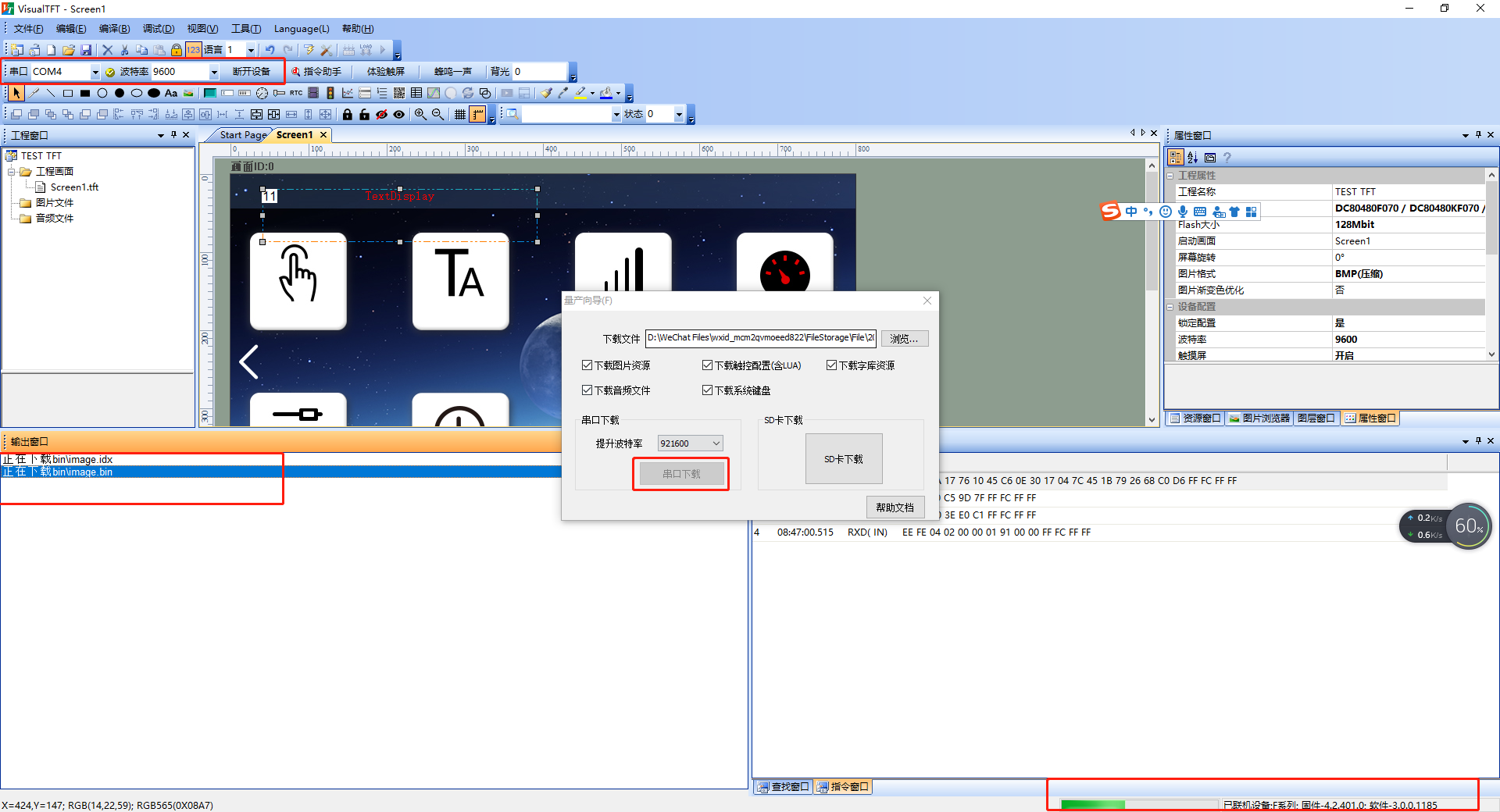
Method 2: SD card download
SD card requirements
⚫ It is recommended to use a Kingston SD card
⚫ with a capacity of less than or equal to 8G
⚫ formatted as FAT32
The upgrade steps are as follows:
① Click on "SD Upgrade Package", and the "SD_PACKET" directory will automatically pop up
② Copy the files in the directory to the root directory of the SD card, as shown below
③ Power off the screen
④ Insert the SD card into the SD card slot of the serial port screen
⑤ Power on the screen, and it will automatically enter the download page
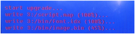
⑥ After the download is complete, the screen will automatically load the project page, and then remove the SD card
IoT type
ClickCompile the project. After successful compilation, the "Mass Production Wizard W" window will automatically pop up. The operation steps are as follows:
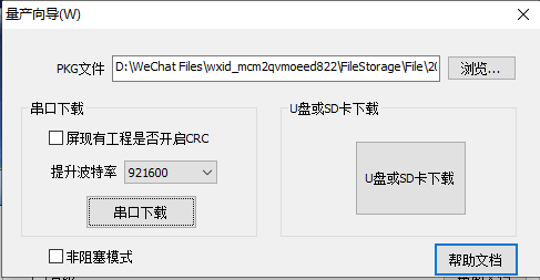
Method 1: Serial Port Download
After successful connection, click on "Serial Port Download" as shown below

Method 2: USB Flash Drive Download
Requirements for USB Flash Drive
⚫ The USB flash drive has not been used as a system boot disk
⚫ The capacity is recommended to be less than or equal to 32G
⚫ Format it as FAT32
Note. Some IoT models only support SD card download, and the download process is similar. ↩
The upgrade steps are as follows:
① Click "Download from U-disk or SD card" to automatically pop up the "Udisk_SD" directory
② Copy the content to the root directory of the U-disk or SD card
③ Power off the screen
④ Insert the U-disk into the U-disk slot of the serial port screen
⑤ Power on the screen to automatically enter the download page
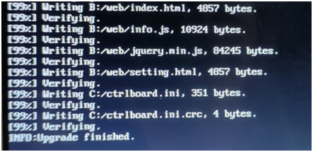
⑥ After the download is complete, the screen displays 'INFO:Upgrade finished', then power off the screen → remove the card → power on, completing the project download
Basic version
Click the Compile button And the [Output Window] displays 0 errors, indicating successful compilation. The operation is as follows:
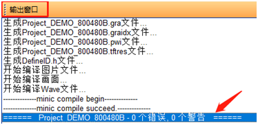
In the menu bar, click "Tools" → "Mass Production Wizard", and the "Mass Production Download" dialog box will pop up
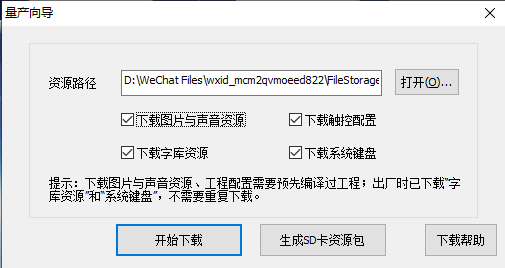
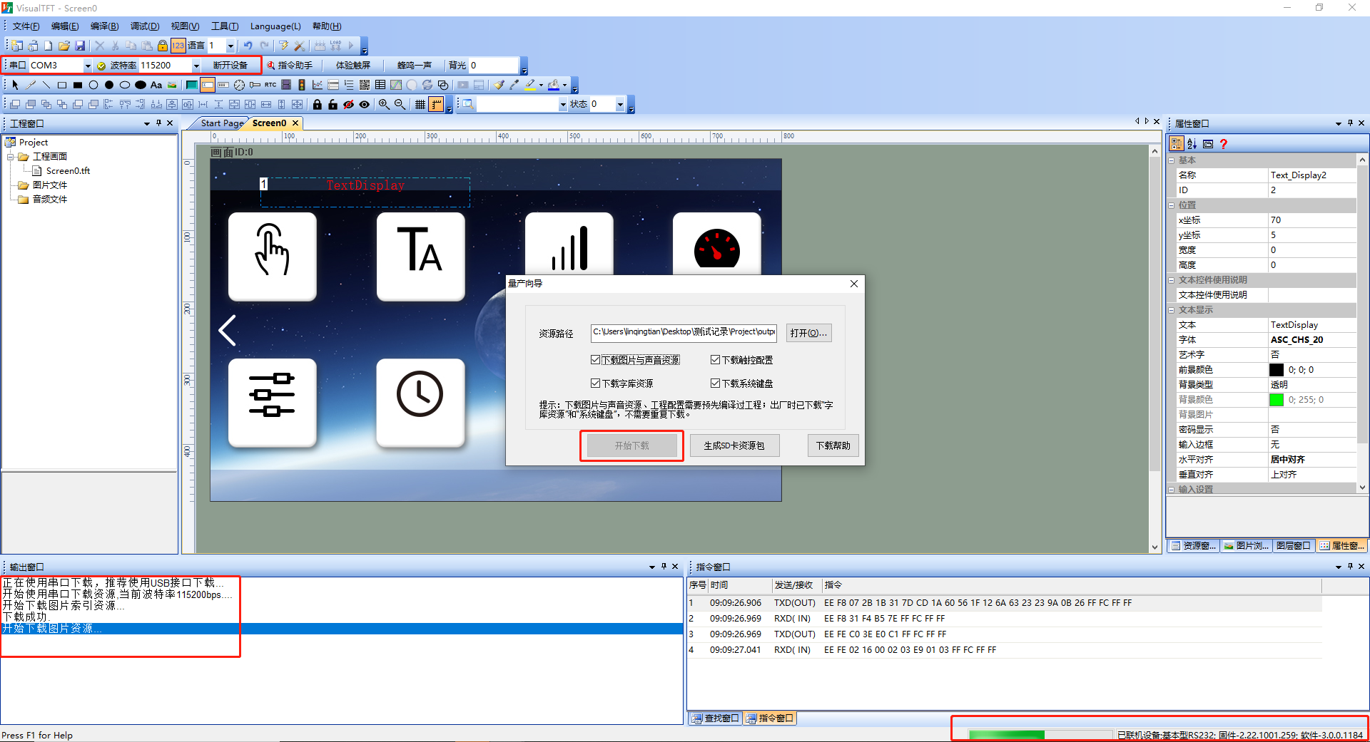
Method 1: Serial Port Download
After successful connection, click on "Serial Port Download" as shown below
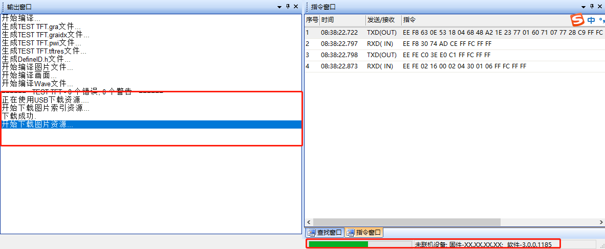
Method 2: Mini USB Port Download
Connect the computer and the screen using the MiniUSB port, clickin the menu bar, and you can enter MiniUSB project download without serial port connection, as shown below
Method 3: U-Disk Download
SD Card Requirements
- It is recommended to use Kingston SD cards
- with a capacity of less than or equal to 8G
- and formatted as FAT32
. The steps for upgrading the SD card are as follows:
① Click to upgrade the SD card resource package
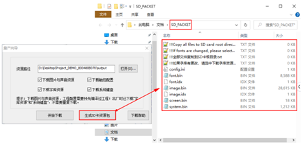
② Copy the content to the root directory of the U-Disk or SD card

③ Insert the SD card into the SD card slot of the serial port screen
④ Automatically enter the upgrade page
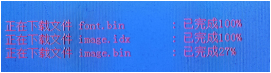
⑤ After the download is complete, the screen buzzer will sound once, and the UI screen will automatically appear. Simply remove the SD card
VisualTFT and virtual screen debugging
Our PC software virtual serial port screen can be debugged in virtual connection with Visual TFT. This feature allows for simulating and demonstrating the interaction between MCU programs and serial port screens on a computer, which is very helpful for beginners to understand the large color instruction set. The software VSPD is a virtual serial port driver generation software that can create a pair of associated virtual serial ports.
Install virtual serial port software
The joint debugging of KEIL software and virtual serial port screen requires a pair of associated virtual serial ports to be implemented. Virtual serial ports can be generated through the VSPD software. If the software VSPD has already been installed, this section can be skipped. The installation steps are as follows:
- The virtual serial port software VSPD installation package is provided on our company's official website and in the software development kit, as shown below:

- Before installing, please review the "Read Me Before Use.txt" document under the installation package. Click to run vspd.exe to install the software, select the installation path, and click "Next" until the installation is complete, as shown below:
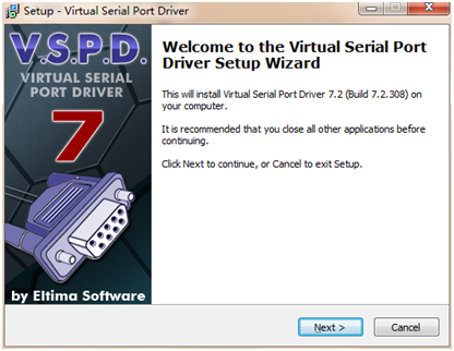
Create a virtual serial port
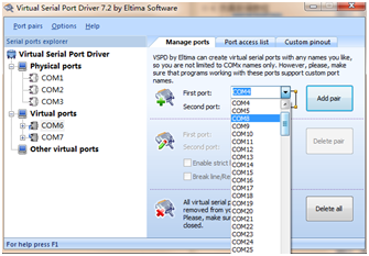
- Open the virtual serial port software. Assuming com6 and com7 are selected as a pair of virtual serial ports, click "Add pair" to generate a pair of associated serial ports, as shown below:
Note: The virtual serial port number cannot be duplicate with the physical serial port number, otherwise the serial port will not function properly. The virtual serial port number should be within 10 as much as possible
Run the virtual screen
Assuming the created virtual serial port pair is com1 and com2, taking the factory project as an example, click "Run", select one of the serial ports, com1, and open the serial port. The operation is shown as follows:
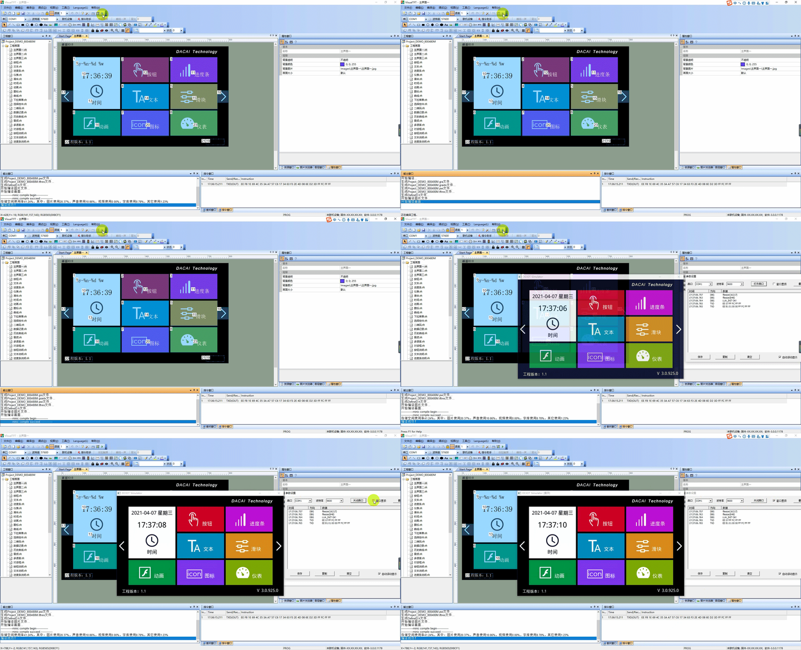
Online Debugging
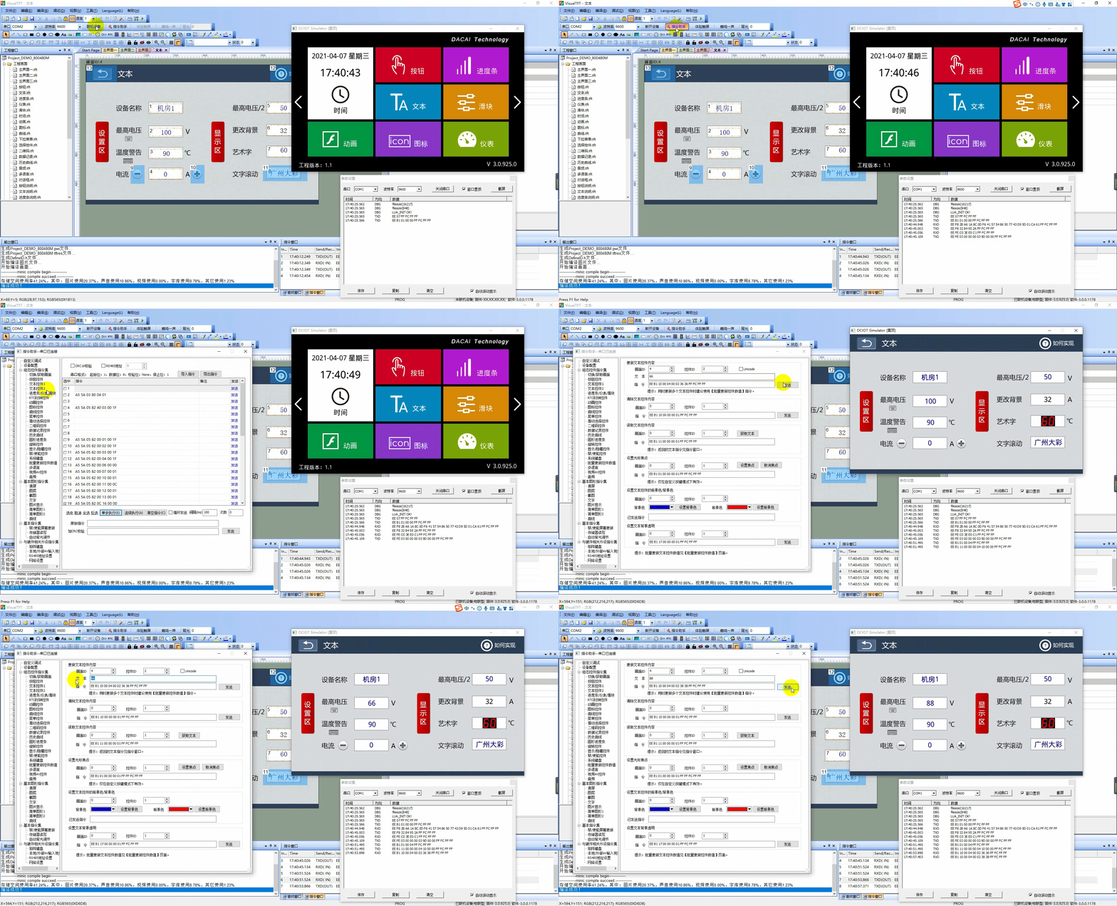
Select the other virtual serial port, com2, open the command assistant, and change the value of the "Maximum Voltage" text control from 100⇨66⇨88. The operation is shown as follows:
Keil and Virtual Screen Debugging
Based on the simulation function of the KEIL development software, our company has added a function for joint debugging with KEIL simulation in the virtual serial port screen on the PC software Visual TFT. This function allows for the simulation demonstration of the interaction effect between the MCU program and the serial port screen on a computer. Using this function to debug programs can greatly reduce the debugging time required for repeatedly downloading MCU programs and serial port screen UI projects during the development process.
The software VSPD is a virtual serial port driver generation software that allows for the creation of a pair of associated virtual serial ports. If the user has already created one in the previous section, they can skip directly to the next section.
Install Virtual Serial Port Software
The joint debugging of KEIL software and virtual serial port screen requires a pair of associated virtual serial ports to be implemented. Virtual serial ports can be generated through the VSPD software. If the software VSPD has already been installed, this section can be skipped. The installation steps are as follows:
- The virtual serial port software VSPD installation package is provided on our company's official website and in the software development package, as shown below:
- Before installing, please review the "Read Me Before Use.txt" document under the installation package. Click to run vspd.exe to install the software, select the installation path, and click "Next" until the installation is complete, as shown below:
Create Virtual Serial Ports
- Open the virtual serial port software, select com6 and com7, and click "Add pair" to generate a pair of associated virtual serial ports. The creation of virtual serial ports is shown as follows:
Note: The virtual serial port number cannot be the same as the physical serial port number, otherwise it will cause the serial port to function improperly. The virtual serial port number should be within 10 as much as possible. If the virtual serial port number exceeds 10, the KEIL software simulator may not support it.
Configure KEIL project properties.
In the previous section, a pair of virtual serial ports, COM6 and COM7, has been generated. Next, we need to connect the virtual serial port screen to COM7, map the KEIL software simulator serial port to COM6, and then configure some properties to complete the connection between the two. The operation steps are as follows:
- View the simulated serial port registers. ARM series MCUs may have multiple serial ports. The method to view the serial port registers is as follows:
① Click the "Debug" button in the KEIL software menu to enter debug mode, and then enter "DIR VTREG" in the lower left corner window of the KEIL project to view how many serial ports are supported by the current MCU simulation, as shown below:
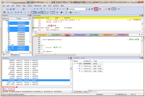
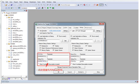
② If it displays that there are currently no serial ports, as shown in Figure 4-5, please check if the simulated MCU is set. The check method is: click "Options for Target" in the toolbar of the KEIL software interface, and select "Debug" in the pop-up window, as shown below:
③ After adding the simulated MCU model, recompile the project, as shown below:
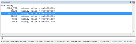
④ After compiling, click the "Debug" button and re-enter "DIR VTREG". If the chip model supports simulation, the serial port registers of the chip will be displayed in the window, as shown below:
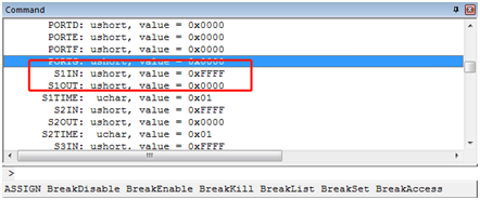
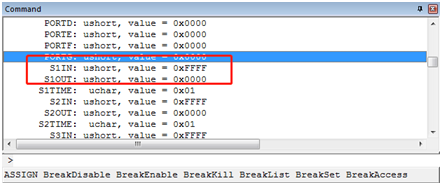
⑤ If the chip model does not support simulation, the serial port registers will not be displayed, as shown below:
- Create a COMDEBUG.ini configuration file.
① In any directory of the KEIL program project, create a new Notepad and name it COMDEBUG.txt, as shown below. Write the following two commands in the text:
MODE COM619200,0,8,1
ASSIGN COM6<S1IN> S1OUT
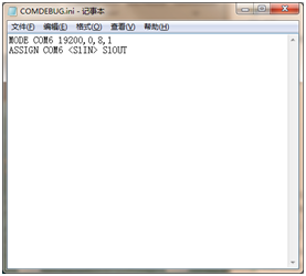
The first command sets the properties of COM6 to a baud rate of 19200, 0 parity bits, 8 data bits, and 1 stop bit; the second command maps the software simulator's serial port 1 to COM6
Special Note: Different MCUs have slight variations in the above ASSIGN statement, as shown below:
ARM Series MCU: ASSIGN COM6 S1OUT
8051 Series MCU: ASSIGN COM6 SOUT
STC Series MCU: ASSIGN COM6 S0OUT
Tip: When simulating MCUs using serial ports other than Serial Port 1, you need to modify the above ASSIGN statement to the corresponding serial port. For example, if Serial Port 2 is used, change S1IN to S2IN and S1OUT to S2OUT
③ Change the suffix of COMDEBUG.txt to COMDEBUG.ini, thus completing the creation of the configuration file, as shown below:
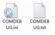
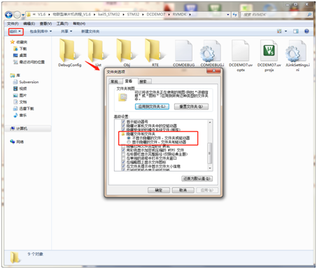
Tip: If the .txt suffix extension is not displayed in Notepad on your computer, you can enter the folder options and remove "Hide file extensions for known file types". For Windows 7 systems, click "Organize" in the file bar and select "Folder and Search Options" to pop up the interface
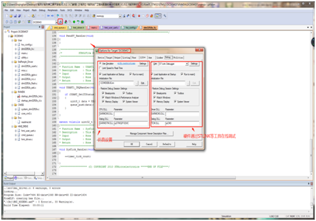
- Open the KEIL project, click "Options for Target" in the toolbar, and select the [Debug] configuration in the pop-up window, as shown below:
- In the [Debug] configuration, select "Use Simulator" on the left side, and add the COMDEBUG.ini configuration file from the project directory to the Initialization File, as shown below:
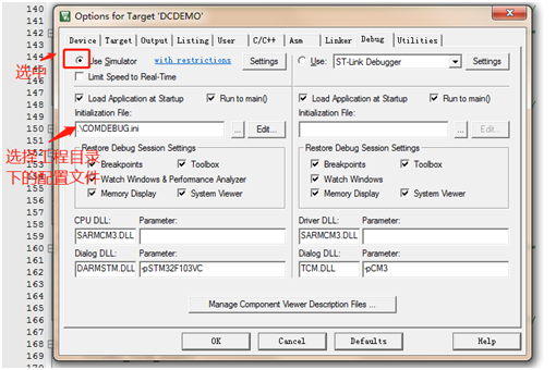
- Then modify the CPU simulation parameters in the window:
[CPU DLL]: Modify to SARMCM3.DLL;
[Parameter]: (Leave blank);
【 Dialog.DLL 】: Change to DARMSTM.DLL;
[Parameter]: -pSTM32F103VC (fill in the simulation chip model here, note: some MCUs do not support simulation function, such as the STM32F4 series of MCUs which do not support software simulation)
Note: The 51 microcontroller does not need to be modified here and can be skipped directly.

Configure the serial port screen project
The project configuration can refer to the factory example in the development package, which will not be detailed here.
- Open the factory example, click to run the virtual serial port screen. After the software compiles successfully, the window of the virtual serial port screen will pop up, as shown below:
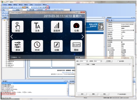
- Select the virtual serial port as com7 and the baud rate as 19200 (the baud rate should be consistent with that in the configuration file), then click to open the serial port and choose whether to make the window topmost according to your needs, as shown below:
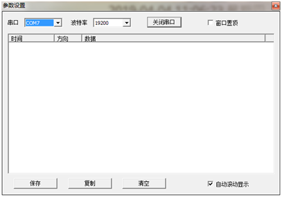
Program joint debugging demonstration
- Click to compile the KEIL project and confirm that there are no errors in the project, as shown below:
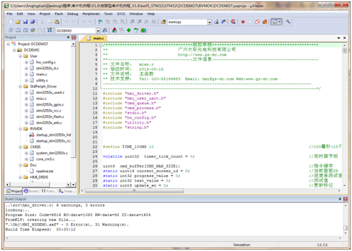
- After successful compilation, click the Debug button, as shown below:
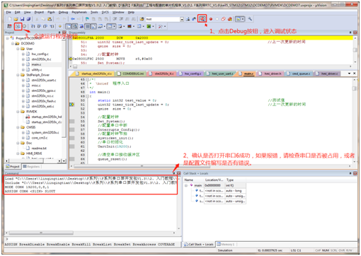
- After starting to run the program at full speed, the effect is as shown below:
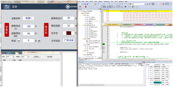
Instruction set
The Bouncing Symbol Protocol is a set of message protocols independently developed and standardized by our company, serving as a standard for communication between user mainboards and Bouncing Symbol serial port screens. The format of a complete serial port command frame is shown below. If the command parameter is greater than 1 byte, the high byte comes first, followed by the low byte. The maximum length of the command is 1024 bytes (including the frame header and frame trailer), with all values in hexadecimal. Serial port format: 8 data bits, 1 stop bit, no parity bit.
| Command | EE | XX | XX XX…XXX | FF FC FF FF |
|---|---|---|---|---|
| Description | Frame Header | Command | Command Parameter | Frame Trailer |
If users require the command to support CRC format verification, the command frame format is shown below. The CRC algorithm program can be downloaded from the official website's download section. CRC verification does not include the frame header and frame trailer.
| Command | EE | XX | XX XX…XXX | CRC16 | FF FC FF FF |
|---|---|---|---|---|---|
| Description | Frame Header | Command | Command Parameter | Check Bit | Frame Tail |
For detailed message meanings and parsing, please refer to "Bouncing Symbol Serial Port Screen Command Set V5.1.pdf" (click to jump)


Leave a Reply