
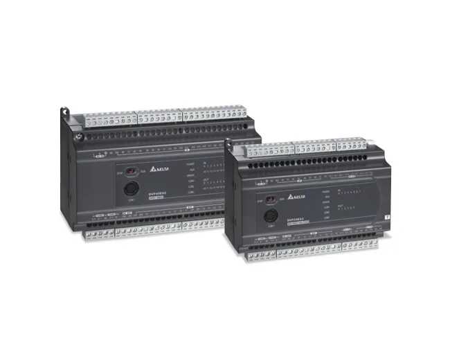
communication port
LRC verification code
COM1After receiving the command message from the master station, the slave station expects a normal response message to be sent to the master station. However, sometimes the PLC does not respond or responds incorrectly after receiving the command message from the master station. The following will describe the situation where the PLC does not respond to the master station equipment or responds incorrectly.
COM2Assuming the number of node states in the request message is n (decimal), the quotient of n/8 is M, and the remainder is N.
ESLow byte dataEX2/SA2 COM3 : RS-485 Communication port, capable of serving as a master or slave station.
SX2 COM3: USB Communication port, Can be used as a slave station.
COM1~COM3 The communication port can be used for Modbus ASCII Or RTU Mode communication.
Communication structure:
| Communication parameters of communication port | RS-232(COM1) | RS-485(COM2) | RS-485(COM3) | USB(COM3) |
| Baud rate | 110~115200 bps | 110~921,000 bps | 110~115200 bps | |
| Data bit length | 7~8 Position | |||
| Parity check bit | Odd check/even check/no check | |||
| Stop data bit length | 1~2 Data bits | |||
| Communication parameter setting register | D1036 | D1120 | D1109 | |
| Maintain communication format | M1138 | M1120 | M1136 | |
| ASCII pattern | Both master and slave stations are valid | Effective from the station | ||
| RTU pattern | Both master and slave stations are valid | Effective from the station | ||
| ASCII /RTU Mode switching | M1139 | M1143 | M1320 | |
| Set a buffer for the communication address of the slave station | D1121 | D1255 | ||
| Read and write data length (ASCII pattern) | 100 A register | |||
| Read and write data length (RTU pattern) | 100 A register |
The default communication format of the communication port
L Modbus ASCII pattern
L 7 Data bits
L 1 A stop position
L Odd check digit (EVEN)
L 9600bps Baud rate
4.2 ASCII Mode communication protocol
Communication data structure
9600 (Baud rate), 7 (Data bits), Even (Parity check bit) 1 (Starting position), 1 (Stop position)
| Field name | form | explain |
| Starting character | STX | The starting character is:’,The colon ASCII The code is 3AH |
| Slave station address | ADR 1 | The communication address consists of two parts ASCII Code composition |
| ADR 0 | ||
| Command code | CMD 1 | The command code consists of two parts ASCII Code composition |
| CMD 0 | ||
| data The data content is composed of: | DATA (0) | one 2n one ASCII Code composition, ns205. |
| DATA (1) | ||
| ……… . | ||
| DATA (n-1) | ||
| LRC Verification code | LRC CHK 1 | LRC Verification code: 2 One ASCII Code composition |
| LRC CHK 0 | ||
| End character | END1 | The ending character is 2 One ASCII Code compositionEND1 = CR (0DH) ,END0 = LF (0AH) |
| END0 |
16 Binary and ASCII The code correspondence relationship is shown in the following table:
| ASCII Code | “0“ | “1“ | “2“ | “3“ | “4“ | “5“ | “6“ | “7“ |
| 16 Base system | 30H | 31H | 32H | 33H | 34H | 35H | 36H | 37H |
| ASCII Code | “8“ | “9“ | “A“ | “B“ | “C“ | “D“ | “E“ | “F“ |
| 16 Base system | 38H | 39H | 41H | 42H | 43H | 44H | 45H | 46H |
4.2.1 ADR (postal address)
The effective range of communication addresses is: 0~254. When the mailing address is 0 Time represents for all PLC radio broadcast, Received broadcast messages PLC can't Responding to broadcast messages. When PLC The address is not 0 Time, PLC Will respond to normal messages to the main station device.
For example, the mailing address is 16 (decimal system) of The address of PLC The code representation method is as follows: decimal number ASCII hexadecimal 16 basesystem is command code and data 10).
(ADR 1, ADR 0)=’1’,’0’s’1’=31H, ‘0’ = 30H
4.2.2 the format of data characters depends on the command code, and the description of valid command codes is shown in the table below
command code:
| read node state (unreadable input node state | ||
| 01 (01 H) | read node state (readable input node state) | S, Y, M, T, C |
| 02 (02 H) | read register content value) | S, X, Y, M,T, C |
| 03 (03 H) | force individual node state | T, C, D |
| 05 (04 H) | preset individual register value On/Off | S, Y, M, T, C |
| 06 (06 H) | force multiple node states | T, C, D |
| 15 (0F H) | preset multiple register values On/Off | S, Y, M, T, C |
| 16 (10 H) | report slave station address | T, C, D |
| 17 (11 H) | perform read and write functions simultaneously within a polling time | None |
| 23 (17 H) | PLC LINK for example read | None |
communication address: address PLC register 01, continuous H0614~H61B (character group data T20~T27) hexadecimal 8 for. 0614 (internal) address PLC internal T20 The address.
PCOnePLC:
“: 01 03 06 14 00 08 DA CR LF”
Request message:
| Field name | ASCII Code | 16 Base system |
| Starting character | : | 3A |
| Slave station address | 01 | 30 31 |
| Command code | 03 | 30 33 |
| High byte starting data address | 06 | 30 36 |
| Low byte starting data address | 14 | 31 34 |
| High byte number of contacts | 00 | 30 30 |
| Low byte number of contacts | 08 | 30 38 |
| LRC Verification code | DA | 44 41 |
| End character | CR LF | 0D 0A |
PLCOnePC
“: 01 03 10 00 01 00 02 00 03 00 04 00 05 00 06 00 07 00 08 C8 CR LF”
Response message:
| Field name | ASCII Code | 16 Base system |
| Starting character | : | 3A |
| Slave station address | 01 | 30 31 |
| Command code | 03 | 30 33 |
| Field name | ASCII Code | 16 Base system |
| Byte count | 10 | 31 30 |
| High byte(T20) | 00 | 30 30 |
| Low byte(T20) | 01 | 30 31 |
| High byte(T21) | 00 | 30 30 |
| Low byte(T21) | 02 | 30 32 |
| High byte(T22) | 00 | 30 30 |
| Low byte(T22) | 03 | 30 33 |
| High byte(T23) | 00 | 30 30 |
| Low byte(T23) | 04 | 30 34 |
| High byte(T24) | 00 | 30 30 |
| Low byte(T24) | 05 | 30 35 |
| High byte(T25) | 00 | 30 30 |
| Low byte(T25) | 06 | 30 36 |
| High byte(T26) | 00 | 30 30 |
| Low byte(T26) | 07 | 30 37 |
| High byte(T27) | 00 | 30 30 |
| Low byte(T27) | 08 | 30 38 |
| LRC Verification code | C8 | 43 38 |
| End character | CR LF | 0D 0A |
4.2.3 LRCVerification (Checksum)
LRC The verification code is from the station address to the last data content 16 Take the opposite of the values obtained by superimposing binary numbers and then add them again 1 The value. As follows: As shown in the example,LRC The value of the verification code is F6(16 Base system). LRC The calculation method of the verification code is as follows::01H+03H+04H+01H+00+01H = 0AH, 0A (16 Add the result obtained by taking the reverse of (base) 1 For F6 (16 Base system).
| Field name | ASCII Code | 16 numeral system |
| Starting character | : | 3A |
| Slave station address | 01 | 30 31 |
| Command code | 03 | 30 33 |
| High byte starting data address | 04 | 30 34 |
| Low byte starting data address | 01 | 30 31 |
| High byte number of contacts | 00 | 30 30 |
| Low byte number of contacts | 01 | 30 31 |
| LRC Verification code | F6 | 46 36 |
| End character | CR LF | 0D 0A |
Abnormal response:
After receiving the command message from the main station, expect a normal response message to be sent to the main station, But sometimes PLC Upon receiving commands from the main station The reasons for not responding or responding incorrectly after the message will be described below PLC The situation where there is no response from the main station device or the reason for the error response is not given.
1. Due to communication errors, PLC Not receiving the correct command message: Therefore, when PLC When there is no response message, the main station device must set a communication timeout condition.
2. When no communication errors occur, PLC Received a valid communication message, But PLC Unable to understand the meaning of this message, So PLC Will provide abnormal response to the main station. The highest bit of the command code for responding to messages will be set to 1 And it will return an exception code indicating the cause of the exception response Reasons for response.
The command code is 01H Example of abnormal response in time, The abnormal response code is 02H
Request message:
| Field name | ASCII Code | hexadecimal |
| Starting character | : | 3A |
| 30 31 | ||
| Slave station address | 01 | |
| Command code | 01 | 30 31 |
| High byte starting data address | 04 | 30 34 |
| Low byte starting data address | 00 | 30 30 |
| High byte number of contacts (Unit: Position) | 00 | 30 30 |
| Low byte number of contacts (Unit: Position) | 10 | 31 30 |
| LRC Verification code | EA | 45 41 |
| End character | CR LF | 0D 0A |
Response message
| Field name | ASCII Code | hexadecimal |
| Starting character | : | 3A |
| 30 31 | ||
| Slave station address | 01 | |
| Command code | 81 | 38 31 |
| 30 32 | ||
| Exception code | 02 | |
| LRC Verification code | 7C | 37 43 |
| End character | CR LF | 0D 0A |
| Exception code | meaning |
| 01 | Illegal command code: PLC The command code in the received command information is invalid |
| 02 | Illegal device address: The address in the received command information is invalid. |
| 03 | Illegal device value: PLC The data content in the received command information is invalid. |
| 07 | 1. Verification and error● Check if the checksum is correct |
| Exception code | meaning |
| 2. Illegal command messages● The command message is too short● The length of the command message exceeds the range |
4.3 RTU Mode communication protocol
Communication data structure
9600 (Baud rate), 8 (Data bits), Even (Parity check bit) 1 (Starting position), 1 (Stop position)
| Start | Maintain no input data≥10 ms |
| Slave station address | Slave station address:: 8 Binary digit address |
| Command code | Command code:: 8 Binary digit address |
| data Data content (n-1) | Binary digitn × 8 data Checksum low byte, n<=202 |
| …… . | |
| Checksum 0 | |
| CRC The checksum consists of two components | CRC Composed of binary digitsCRC Checksum high byte 8 end |
| CRC Maintain no input data | |
| Address | postal address≥10 ms |
4.3.1 The effective range of communication addresses is: (When the mailing address is)
Time represents for all 0~254. radio broadcast 0 Received broadcast messages PLC can't, Responding to broadcast messages PLC When The address is not. Time PLC Will respond to normal messages to the main station device 0 For example, PLC When the communication address is.
decimal system, of When communicating 16 (The address of the slave station must be set as) Base system PLC Decimal numbers, The hexadecimal system is 10 (16 Command codes and data), The format of data characters depends on the command code 16 The hexadecimal system is 10).
4.3.2 Command codes and data
The format of data characters depends on the command code, Please refer to the description of the valid function code 4.2.2 Festival.
example: Read PLC Station number 01, Address H0614~H61B (T20~T27)Continuity 8 Data of character sets. Read slave devices (Tong The mailing address is: 1)The value.
PCOnePLC
“ 01 03 06 14 00 08 04 80”
Sending messages:
| Field name | data Base system (16 Start) |
| Maintain no input data | Slave station address≥10 ms |
| Command code | 01 |
| Starting address of data | 03 |
| Field name | 06 |
| data Base system | Number of data (in bytes (16 checksum low byte) |
| 14 | |
| checksum high byte) | 00 |
| 08 | |
| CRC end | 04 |
| CRC keep no input data | 80 |
| one | response message≥10 ms |
PLCfield namePC
“ 01 03 10 00 01 00 02 00 03 00 04 00 05 00 06 00 07 00 08 72 98”
data:
| base | start (16 keep no input data) |
| slave address | command code≥10 ms |
| number of data (in bytes | 01 |
| data high byte | 03 |
| data low byte) | 10 |
| data high byte (T20) | 00 |
| data low byte (T20) | 01 |
| data high byte (T21) | 00 |
| data low byte (T21) | 02 |
| data high byte (T22) | 00 |
| data low byte (T22) | 03 |
| data low byte (T23) | 00 |
| data low byte (T23) | 04 |
| data high byte (T24) | 00 |
| data low byte (T24) | 05 |
| data high byte (T25) | 00 |
| data high byte (T25) | 06 |
| data high byte (T26) | 00 |
| data low byte (T26) | 07 |
| data low byte (T27) | 00 |
| data low byte (T27) | 08 |
| CRC checksum low byte | 72 |
| CRC checksum high byte | 98 |
| end | keep no input data)≥10 ms |
4.3.3 CRC Verification (Checksum)
CRC Verify from "starting from the station address" to "ending with the last data content". The verification calculation method is as follows: steps: load a content value of "hexadecimal"" bit register (called "register". CRC step ": the first byte of the instruction message 1 : bit data and" register low byte " FFFF (XOR the bit data) store the result in the register 16 step CRC move the content value of the register to the right).
bit and fill in its highest bit 2 : step 8 check CRC check the value of the lowest bit of the register, if it is" 8 repeat step if it is " CRC register content and" hexadecimal ") for XOR operation.
store the operation result in the register 3: CRC step 1 repeat step 0.
and step 4: until CRC register The content has been shifted to the right by 0 bit 3:at this time 1 , CRC the first byte of the instruction message A001 (processing has been completed, step CRC repeat step to the next byte of the instruction message.
operation to step 5 : Until all bytes of the instruction message have been processed 3 Cheng 4,The final content of the register is:CRC Verification value8 Transmitting in command messages. When verifying values, Calculated School.
The high and low bytes of the verification value must be exchanged 6 : That is 2 The low byte of the verification value is transmitted first 5 Below is for use, Language demand Calculation example of verification value. CRC Instruction message content pointer CRC The length of the command message. Abnormal response CRC When verifying values, Calculated CRC school The high and low bytes of the verification value must be exchanged, namely CRC The low byte of the verification value is transmitted first.
Below is for use C Language Request CRC Calculation Example of Verification Value
unsigned char* data <// Command message content pointer
unsigned char length <// The length of the command message
unsigned int crc_chk(unsigned char* data, unsigned char length)
{
int j;
unsigned int reg_crc=0Xffff;
while(length--)
{
reg_crc ^= *data++;
for (j=0;j<8;j++)
{
If (reg_crc & 0x01) reg_crc=(reg_crc>>1) ^ 0Xa001; /* LSB(b0)=1 */
else reg_crc=reg_crc >>1;
}
}
return reg_crc; // the value that sent back to the CRC register finally
}
Abnormal response:
After receiving the command message from the main station, expect a normal response message to be sent to the main station, But sometimes PLC Upon receiving commands from the main station The reasons for not responding or responding incorrectly after the message will be described below PLC The situation where there is no response from the main station device or the reason for the error response is not given.
1. Due to communication errors, PLC Not receiving the correct command message: Therefore, when PLC When there is no response message, the main station device must set a communication timeout condition.
2. When no communication errors occur, PLC Received a valid communication message, But PLC Unable to understand the meaning of this message, So PLC Will provide abnormal response to the main station. The highest bit of the command code for responding to messages will be set to 1 And it will return an exception code indicating the cause of the exception response Reasons for response.
The following example is the command code: 01H Example of abnormal response in time, The abnormal response code is 02H.
Sending messages:
| Field name | data Base system (16 Start) |
| Maintain no input data | Slave station address≥10 ms |
| Command code | 01 |
| Starting address of data | 01 |
| Number of data (in bytes | 04 |
| 00 | |
| checksum low byte) | 00 |
| 10 | |
| CRC checksum high byte | 3C |
| CRC end | F6 |
| keep no input data | response message≥10 ms |
field name:
| base(16 start) | |
| keep no input data | slave address≥10 ms |
| command code | 01 |
| exception code | 81 |
| checksum low byte | 02 |
| CRC checksum high byte | C1 |
| CRC end | 91 |
| keep no input data | device address≥10 ms |
PLCdevice
| valid range | address | MODBUSodd address valid | device | ||
| ES2/EX2 | SS2 | SA2/SX2 | |||
| S | 000~255 | 000~1023 | 000~1023 | 000001~000256 | 0000~00FF |
| S | 256~511 | 000257~000512 | 0100~01FF | ||
| S | 512~767 | 000513~000768 | 0200~02FF | ||
| S | 768~1023 | 000769~001024 | 0300~03FF | ||
| X | 000~377 (Octal) | 000~377 | 000~377 | 101025~101280 | 0400~04FF |
| Y | 000~377 (Octal) | 000~377 | 000~377 | 001281~001536 | 0500~05FF |
| T | 000~255 bit | 000~255 | 000~255 | 001537~001792 | 0600~06FF |
| 000~255 word | 000~255 | 000~255 | 401537~401792 | 0600~06FF | |
| M | 000~255 | 0000~4095 | 0000~4095 | 002049~003584 | 0800~08FF |
| M | 256~511 | 0900~09FF | |||
| M | 512~767 | 0A00~0AFF | |||
| M | 768~1023 | 0B00~0BFF | |||
| M | 1024~1279 | 0C00~0CFF | |||
| M | 1280~1535 | 0D00~0DFF | |||
| M | 1536~1791 | 045057~047616 | B000~B0FF | ||
| M | 1792~2047 | B100~B1FF | |||
| M | 2048~2303 | B200~B2FF | |||
| M | 2304~2559 | B300~B3FF | |||
| M | 2560~2815 | B400~B4FF | |||
| M | 2816~3071 | B500~B5FF | |||
| M | 3072~3327 | B600~B6FF | |||
| M | 3328~3583 | B700~B7FF | |||
| M | 3584~3839 | B800~B8FF | |||
| M | 3840~4095 | B900~B9FF | |||
| C | 000~199 (16-bit) | 000~199 | 000~199 | 003585~003784 | 0E00~0EC7 |
| 000~199 | 000~199 | 403585~403784 | 0E00~0EC7 | ||
| 200~255 (32-bit) | 200~255 | 200~255 | 003785~003840 | 0EC8~0EFF | |
| 200~255 | 200~255 | 401793~401903(range) | 0700~076F |
| valid range | address | device communication address) | MODBUSaddress | Device communication address | ||
| ES2/EX2 | SS2 | SA2/SX2 | ||||
| D | 000~255 | 0000~9999 | 0000~4999 | 0000~9999 | 404097~405376 | 1000~10FF |
| D | 256~511 | 1100~11FF | ||||
| D | 512~767 | 1200~12FF | ||||
| D | 768~1023 | 1300~13FF | ||||
| D | 1024~1279 | 1400~14FF | ||||
| D | 1280~1535 | 405377~408192 | 1500~15FF | |||
| D | 1536~1791 | 1600~16FF | ||||
| D | 1792~2047 | 1700~17FF | ||||
| D | 2048~2303 | 1800~18FF | ||||
| D | 2304~2559 | 1900~19FF | ||||
| D | 2560~2815 | 1A00~1AFF | ||||
| D | 2816~3071 | 1B00~1BFF | ||||
| D | 3072~3327 | 1C00~1CFF | ||||
| D | 3328~3583 | 1D00~1DFF | ||||
| D | 3584~3839 | 1E00~1EFF | ||||
| D | 3840~4095 | 1F00~1FFF | ||||
| D | 4096~4351 | 436865~440960 | 9000~90FF | |||
| D | 4352~4607 | 9100~91FF | ||||
| D | 4608~4863 | 9200~92FF | ||||
| D | 4864~5119 | 9300~93FF | ||||
| D | 5120~5375 | None | 9400~94FF | |||
| D | 5376~5631 | 9500~95FF | ||||
| D | 5632~5887 | 9600~96FF | ||||
| D | 5888~6143 | 9700~97FF | ||||
| D | 6144~6399 | 9800~98FF | ||||
| D | 6400~6655 | 9900~99FF | ||||
| D | 6656~6911 | 9A00~9AFF | ||||
| D | 6912~7167 | 9B00~9BFF | ||||
| D | 7168~7423 | 9C00~9CFF | ||||
| D | 7424~7679 | 9D00~9DFF | ||||
| D | 7680~7935 | 9E00~9EFF | ||||
| D | 7936~8191 | 9F00~9FFF | ||||
| D | 8192~8447 | 440961~442768 | A000~A0FF | |||
| D | 8448~8703 | A100~A1FF | ||||
| D | 8704~8959 | A200~A2FF | ||||
| D | 8960~9215 | A300~A3FF | ||||
| D | 9216~9471 | A400~A4FF | ||||
| D | 9472~9727 | A500~A5FF | ||||
| D | 9728~9983 | A600~A6FF | ||||
| D | 9984~9999 | A700~A70F |
4.5 Command code
4.5.1 Command code: 01, Read node status(Unreadable input point status)
Maximum number of data points= 255 (10 Base system) = FF (16 Base system)
Example: Read the node status of the slave device (communication address:) 1)T20~T56 1.
PCsend messagePLC: “:01 01 06 14 00 25 BF CR LF”
field name:
| code | ASCII start character |
| slave address | : |
| command code | 01 |
| start data address high byte | 01 |
| start data address low byte | 06 |
| node status high byte | 14 |
| node status low byte | 00 |
| checksum | 25 |
| LRC end character | BF |
| end character 1 | 0D (Hex) |
| assuming the number of node statuses in the request message is 0 | 0A (Hex) |
decimal n (quotient is), n/8 remainder is M,when N..
when N=0 byte number in the response message is, when M;byte number in the response message is N≠0 one, response message M+1. PLCfield namePC: “:01 01 05 CD 6B B2 0E 1B D6 CR LF”
code:
| start character | ASCII slave address |
| command code | : |
| byte number | 01 |
| node status | 01 |
| node status | 05 |
| T20~T27 node status | CD |
| T35~T38 node status | 6B |
| T36~T43 Node status | B2 |
| T44~T51 Node status | 0E |
| T52~T56 Check code | 1B |
| LRC End character | E6 |
| End character 1 | 0D (Hex) |
| Command code 0 | 0A (Hex) |
4.5.2 Read node status: 02,Read input node status(Example: Read the node status of the slave device (communication address:))
Send message 1) Y024~Y070 Field name.
PCCodePLC “: 01 02 05 14 00 25 BF CR LF”
Starting character:
| field name | ASCII code |
| Starting character | : |
| Slave station address | 01 |
| Command code | 02 |
| High byte starting data address | 05 |
| Low byte starting data address | 14 |
| High number of data bytes | 00 |
| Low byte data count | 25 |
| LRC Verification code | BF |
| End character 1 | 0D (Hex) |
| End character 0 | 0A (Hex) |
Assuming the number of node states in the request message is n (decimal system), n/8 The business is M,The remainder is N..
When N=0 Time, The number of bytes in the response message is M;When N≠0 Time, The number of bytes in the response message is M+1. PLCOnePC “: 01 01 05 CD 6B B2 0E 1B E5 CR LF”
Response message:
| ASCII Code | |
| Starting character | : |
| Slave station address | 01 |
| Command code | 02 |
| Number of bytes | 05 |
| Y024~Y033 Node status | CD |
| Y034~Y043 Node status | 6B |
| Y044~Y053 Node status | B2 |
| Y054~Y063 Node status | 0E |
| Y064~Y070 Node status | 1B |
| LRC Verification code | E5 |
| End character 1 | 0D (Hex) |
| End character 0 | 0A (Hex) |
4.5.3 Command code: 03,Read the register contents value
Command code 03 Readable registers: T, C, D
example::Read the slave station address as: 1 of of The content value PLC One T20~T27 Sending messages.
PCField namePLC: “: 01 03 06 14 00 08 DA CR LF”
Code:
| ASCII Slave station address | |
| Command code | : |
| High byte data address | 01 |
| High byte starting data address | 03 |
| Read high byte count of data | 06 |
| Read the low byte of the number of data (number of data in words | 14 |
| checksum | 00 |
| end character) | 08 |
| LRC end character | DA |
| one 1 | 0D (Hex) |
| response message) 0 | 0A (Hex) |
PLCOnePC: “:01 03 10 00 01 00 02 00 03 00 04 00 05 00 06 00 07 00 08 B8 CR LF” Response message:
| Field name | ASCII Code |
| Starting character | 3A |
| Slave station address | 01 |
| Command code | 03 |
| Number of bytes | 10 |
| High byte data (T20) | 00 |
| Low byte data (T20) | 01 |
| High byte data (T21) | 00 |
| Low byte data (T21) | 02 |
| High byte data (T22) | 00 |
| Low byte data (T22) | 03 |
| High byte data (T23) | 00 |
| Low byte data (T23) | 04 |
| High byte data (T24) | 00 |
| Low byte data (T24) | 05 |
| High byte data (T25) | 00 |
| Low byte data (T25) | 06 |
| High byte data (T26) | 00 |
| Low byte data (T26) | 07 |
| Field name | ASCII Code |
| High byte data (T27) | 00 |
| Low byte data (T27) | 08 |
| LRC Verification code | C8 |
| End character 1 | 0D (Hex) |
| End character 0 | 0A (Hex) |
4.5.4 Command code: 05, Enforce separate node status
The command code is 05 Mandatory data FF00 (16 Binary system) represents forcing a node to On; Mandatory data 0000 (16 Binary system) represents forcing a node to Off. Other mandatory data is invalid and will not affect the mandatory nodes.
Example: Mandatory Y0 Node is On.
PCOnePLC “: 01 05 05 00 FF 00 F6 CR LF”
Sending messages:
| Field name | ASCII Code |
| Starting character | : |
| Slave station address | 01 |
| Command code | 05 |
| Node address high byte | 05 |
| Node address low byte | 00 |
| Force high byte data | FF |
| Mandatory low byte data | 00 |
| LRC Verification code | F6 |
| End character 1 | 0D (Hex) |
| End character 0 | 0A (Hex) |
PLCOnePC “: 01 05 05 00 FF 00 F6 CR LF”
Responding to information:
| Field name | ASCII Code |
| Starting character | : |
| Slave station address | 01 |
| Command code | 05 |
| Node address high byte | 05 |
| Node address low byte | 00 |
| Force high byte data | FF |
| Mandatory low byte data | 00 |
| LRC Verification code | F6 |
| End character 1 | 0D (Hex) |
| End character 0 | 0A (Hex) |
4.5.5 Command code: 06, Preset the value of a separate register
example: :Set registers T0 The value is 12 34 (16 Base system), T0 The mailing address is: 0600 (16 Base system). PCOnePLC “: 01 06 06 00 12 34 AD CR LF”
Sending messages:
| Field name | ASCII Code |
| Starting character | : |
| Slave station address | 01 |
| Command code | 06 |
| Register address high byte | 06 |
| Register address low byte | 00 |
| Preset high byte data value | 12 |
| Low byte preset data value | 34 |
| LRC Verification code | AD |
| End character 1 | 0D (Hex) |
| End character 0 | 0A (Hex) |
PLCOnePC “: 01 06 06 00 12 34 AD CR LF”
Responding to information:
| Field name | ASCII Code |
| Starting character | : |
| Slave station address | 01 |
| Command code | 06 |
| Register address high byte | 06 |
| Register address low byte | 00 |
| Preset high byte data value | 12 |
| Low byte preset data value | 34 |
| LRC Verification code | AD |
| End character 1 | 0D (Hex) |
| End character 0 | 0A (Hex) |
4.5.6 Command code: 15, Enforce multiple nodes
Maximum number of nodes = 255
Example: Setting up nodes Y007…Y000 = 1100 1101, Y011…Y010 = 01.
PCOnePLC: “: 01 0F 05 00 00 0A 02 CD 01 11 CR LF”
Sending messages:
| Field name | ASCII Code |
| Starting character | 3A |
| Slave station address | 01 |
| Command code | 0F |
| Field name | ASCII Code |
| Node address high byte | 05 |
| Node address low byte | 00 |
| High number of nodes in bytes | 00 |
| Low number of nodes in bytes | 0A |
| Number of bytes | 02 |
| Force high byte data | CD |
| Mandatory low byte data | 01 |
| LRC Verification code | 11 |
| End character 1 | 0D (Hex) |
| End character 0 | 0A (Hex) |
PLCOnePC: “: 01 0F 05 00 00 0A E1 CR LF”
Responding to information:
| Field name | ASCII Code |
| Starting character | : |
| Slave station address | 01 |
| Command code | 0F |
| High byte starting data address | 05 |
| Low byte starting data address | 00 |
| Preset high byte data value | 00 |
| Low byte preset data value | 0A |
| LRC Verification code | E1 |
| End character 1 | 0D (Hex) |
| End character 0 | 0A (Hex) |
4.5.7 Command code: 16, Preset values for multiple registers
Example: Settings T0 The value is 000A (16 Base system),set up T1 The value is 0102 (16 Base system).
PCOnePLC: “: 01 10 06 00 00 02 04 00 0A 01 02 D6 CR LF”
Sending messages:
| Field name | ASCII Code |
| Starting character | : |
| Slave station address | 01 |
| Command code | 10 |
| High byte starting data address | 06 |
| Low byte starting data address | 00 |
| High number of registers in bytes | 00 |
| Low number of registers in bytes | 02 |
| Number of data (in bytes) | 04 |
| data high byte | 00 |
| data low byte | 0A |
| data high byte | 01 |
| data low byte | 02 |
| LRC checksum | D6 |
| end character 1 | 0D (Hex) |
| end character 0 | 0A (Hex) |
PLConePC: “: 01 10 06 00 00 02 E7 CR LF”
response message:
| field name | ASCII code |
| start character | : |
| slave address | 01 |
| command code | 10 |
| start data address high byte | 06 |
| start data address low byte | 00 |
| register high byte | 00 |
| register low byte | 02 |
| LRC checksum | E7 |
| end character 1 | 0D (Hex) |
| end character) 0 | 0A (Hex) |


Leave a Reply