

Source: Modbus Chinese Network (modbus. cn) - a leading Modbus communication protocol technology community in China
This article: Progressive Solution to Modbus Communication Issues: A Complete Troubleshooting Manual from Physical Layer to Application · Author: Modbus Technical Team · Published on July 1, 2026
Summary: What should I do if Modbus RS-485 communication is not working? This article demonstrates a complete progressive troubleshooting method from the physical layer to the application layer through real message analysis and troubleshooting tools. Keywords: Modbus communication troubleshooting, RS-485 troubleshooting, Modbus debugging methods, Modbus RTU unresponsive, CRC verification error.
In the field of industrial automation, Modbus communication problems are the most headache inducing issue - not because it is complex, but because the fault points are too scattered. If any link in the physical layer, data link layer, or application layer encounters a problem, the phenomenon may be the same:The master station sends a request, but the slave station does not reply.
This article is not about teaching you the basics of Modbus protocol. I assume you are already using Modbus and the current issue is' not working '. You need a troubleshooting checklist that can be followed. Let's start from the bottom and look up layer by layer.
Core keywords: Modbus communication troubleshooting, RS-485 troubleshooting, Modbus RTU unresponsive, CRC check error. For more Modbus technology articles, please visit modbus.cn.
1, What does a typical on-site fault look like
First, let's take a look at three real-life scenarios. If you have encountered similar ones, this article is written for you.
Scenario 1: A sewage treatment plant has 16 Modbus RTU slave stations connected to an RS-485 bus. All disconnections occur promptly at 3 pm every day, and will automatically resume after ten minutes. After checking for three weeks, it was finally found that the photovoltaic inverter in the adjacent pump room starts at 3 pm every day, and EMI interference couples to the 485 line, flooding the signal.
Scenario 2: A Mitsubishi inverter is connected to the gateway through RS-485, and the main station sends function code 03 to read the frequency. Occasionally, it can read and occasionally reports CRC errors. The baud rate is 9600. After two days of tinkering, I finally found out that the A/B line was connected incorrectly - A from the master station was connected to B from the slave station. But why can I occasionally read data? Because RS-485 transceivers have a certain common mode tolerance, they can truly communicate when the signal quality is good, but CRC errors occur when there is interference.
Scenario 3: A new temperature controller has been added to the production line, with the address set to 05. After hanging it up, there is no response from 05, but the original one from 07 is also not working. Unplug the new device and restore normal operation on the 7th. In the end, the new device was configured with a default 120 Ω terminal resistor, and there were a total of three terminal resistors hanging on the bus - impedance mismatch, signal reflection causing all slave stations to be intermittent.
These three scenarios point to the same principle:Modbus is not working, we cannot guess, we need to eliminate it layer by layer.Here is the complete path for this investigation.
2, Overview of Investigation: A Four Layer Model from Physical Layer to Application Layer
The troubleshooting path for Modbus communication issues, in descending order of hierarchy:
┌────────────────────────────────────────────┐
│  第四层:应用层                             │
│  从站地址、寄存器映射、功能码、字节序       │
│  现象:从站回异常码,或数据值明显不对       │
├────────────────────────────────────────────┤
│  第三层:数据链路层                         │
│  波特率、校验位、CRC/LRC 校验               │
│  现象:CRC 错误、帧不完整、偶发性丢帧       │
├────────────────────────────────────────────┤
│  第二层:电气层                             │
│  A/B 线接法、终端电阻、偏置电阻、接地       │
│  现象:完全不通、数据全是乱码、间歇性断连   │
├────────────────────────────────────────────┤
│  第一层:物理连接                           │
│  线缆通断、接头氧化、屏蔽层、布线路径       │
│  现象:主站发数据,从站完全无反应           │
└────────────────────────────────────────────┘
The iron rule of troubleshooting: always start troubleshooting from the first level, confirm that there are no problems before moving forward.I don't know how many people wasted three days on the third layer (changing baud rate, changing timeout), only to find out that the A/B line on the first layer was connected incorrectly. If you only remember one sentence, remember this sentence.
3, First layer: Physical connection check
3.1 Wiring of a multimeter - the most basic first step
Turn off all devices first. Set the multimeter to the resistance or on-off mode and measure:
-Is the A line conducting from the master station to the farthest slave station (resistance should be<10 Ω, depending on the length and diameter of the line)? - Similarly, the B line cannot be short circuited between A and B (resistance should be infinite or close to infinite). - A/B should not be short circuited to GND respectively
If both on and off are normal, then turn on the power and set the multimeter to DC voltage mode:
-A to GND: about 2.5V~3.5V in static state (depending on bias circuit) - B to GND: about 1.5V~2.5V in static state - A-B differential voltage: about 0.2V~2V in static state, A should be higher than B
If the A-B differential voltage is close to 0V, or even A is lower than B, there is a problem with your bias circuit.Many cheap USB-485 converters do not have built-in bias resistors. When working on a long bus, the A-B differential will drift to an uncertain state in idle mode, causing the UART of the slave station to receive random junk data.
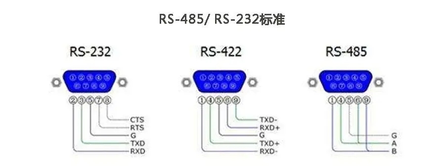
How to connect the A/B line in 3.2? - This pit has the most people stepping on it
There is no unified industry label standard for the A/B wiring of RS-485. The definitions of A and B by different device manufacturers may be reversed. Here are the tagging methods you may encounter and their corresponding relationships:
| Common markings | Another type of marking | Idle voltage | Instructions |
|---|---|---|---|
| A/+/D+/TX+/Positive | Non-Inverting | Higher than B | In-phase end |
| B/-/D -/TX -/Negative | Inverting | Below A | Reverse end |
Quick determination method: Use a multimeter diode to measure in the power-off state.Connect the red probe to GND and the black probe to A - Most RS-485 transceiver chips (such as MAX485, SN75176) have a reverse protection diode on pin A to GND, which measures a forward voltage drop of about 0.6V. The same applies to pin B. If it cannot be measured, change the polarity and test again.
There is a more violent method: if the connection doesn't work, try swapping A and B. Not a joke - this is the most commonly used "troubleshooting method" on site. Because many frequency converters have RS-485 terminal labels that are reversed.
3.3 Terminal Resistance - When and Where to Connect
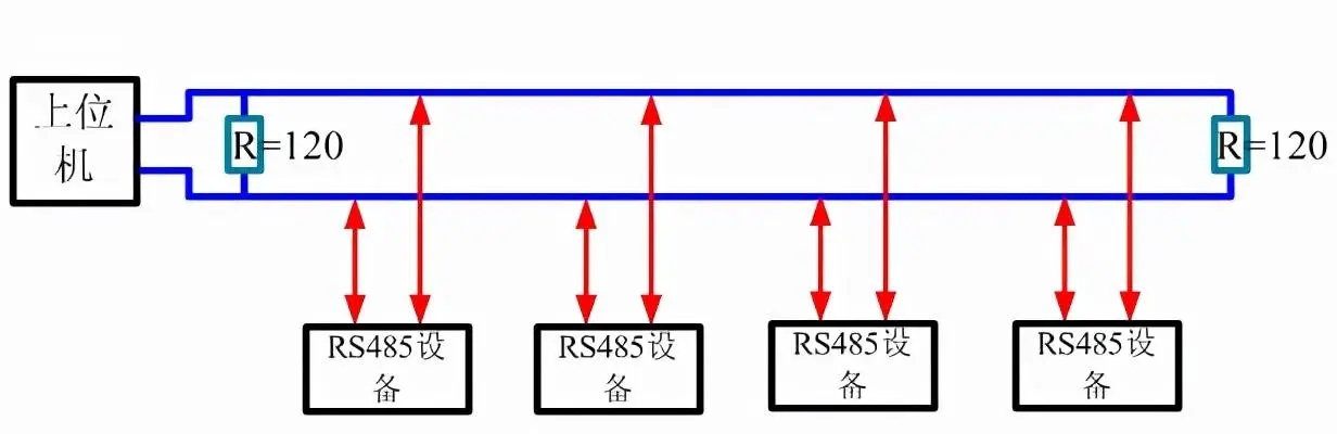
The terminal resistance is 120 Ω, connected to the two ends of the bus. Everyone has heard this sentence before. But in actual engineering, these details determine success or failure:
When must I take it.Bus length exceeding 50 meters, or baud rate ≥ 19200. The criterion for judgment is not length, but using an oscilloscope to observe the signal waveform - if there are obvious overshoot or reflection steps, add terminal resistors.
When can I not answer.On the test bench, a one meter short line with a baud rate of 9600. At this point, adding terminal resistors may actually lead to a decrease in signal amplitude due to insufficient driving capability.
A pit that is easily overlooked.Many RS-485 devices have integrated terminal resistors internally, which can be enabled through jumpers or dip switches. If you don't know this, manually adding 120 Ω on the bus and keeping 120 Ω on the device is equivalent to paralleling it to 60 Ω - the signal amplitude drops significantly, making it even less coherent. This is the previous scene 3.
Troubleshooting method: Turn off all devices and measure the DC resistance between A-B using a multimeter in the resistance range. Normally, it should be several k Ω to tens of k Ω (determined by bias resistance). If it measures 60 Ω or 120 Ω, it indicates that at least one terminal resistor is active. Pull out each device one by one and see which one changes impedance after unplugging.
3.4 Shielding and Grounding - Where Most People Make Mistakes
The RS-485 shielding layer shouldSingle ended groundingConnect to the ground on the main station or gateway side. If both ends are grounded, the ground potential difference will form a circulating current on the shielding layer, which will instead introduce interference into the signal line.
Also, do not use idle Ethernet cables for RS-485. The network cable has a characteristic impedance of 100 Ω, while the RS-485 cable has a characteristic impedance of 120 Ω. Mismatching can cause severe signal reflection at high rates. Short distance (<10 meters) is acceptable, but should not be used as a formal engineering plan. A regular RS-485 cable is a pair of twisted pair wires with a shielding layer, with a characteristic impedance of 120 Ω, such as Belden 3105A or equivalent model.
4, Second layer: Electrical layer inspection
After confirming that there is no problem with the physical connection, if there is still no connection or error, enter the electrical layer.
4.1 Using an oscilloscope to observe waveforms
Hang the oscilloscope probe on line A to GND and line B to GND, observe:
-Whether the voltage values of A and B are stable in idle state (A should be at least 200mV higher than B) - Whether A and B exhibit standard differential signals (A and B mirror symmetry) during data transmission - Whether the rising and falling edges of the waveform are clean (there should be no obvious steps or arcs)
If the waveform edge is very round, it may be due to the cable capacitance being too large (the wire is too long or the wire diameter is too thin), or insufficient driving capability. Reducing the baud rate can usually alleviate the situation.
4.2 Bias Resistance (Fail Safe Bias)
The RS-485 standard requires a differential input voltage of ≥ 200mV to be judged as logic 1, and ≤ -200mV to be judged as logic 0. But when the bus is idle (all devices are not driven), the differential voltage may fall within an uncertain range of -200mV to+200mV, causing the receiver to output random data.
That's why bias resistors are needed: at a certain position on the bus (usually at the main station or bias circuit), two resistors are used to pull A up to VCC and B down to GND, ensuring that A>B and the difference>200mV in idle state.
The common bias resistance values are 680 Ω or 560 Ω (one for pull-up and one for pull-down). However, it should be noted that the bias resistor and the terminal resistor are in parallel. If your terminal resistance is 120 Ω and the bias resistance is 680 Ω each, the actual idle differential voltage is:
V_diff = VCC × R_term / (R_term + R_pullup + R_pulldown)
       = 5V × 120 / (120 + 680 + 680) ≈ 0.405V = 405mV
This value is greater than 200mV, meeting the requirements. But if you replace the terminal resistor with 60 Ω (two 120 Ω in parallel), the differential voltage will only be about 210mV, stuck at the critical point. So the number and location of terminal resistors are prerequisites for planning bias resistors.
5, Layer 3: Data Link Layer Inspection
There is no problem with the electrical layer, but the communication is still incorrect - troubleshooting the protocol itself. This layer requires a serial packet capture tool.
5.1 Confirm if the slave station supports Modbus
This is not for you to read the device manual - just because the manual says support doesn't mean the firmware is actually turned on. Use the serial assistant to send the simplest request frame and see if the slave can reply.
Taking Modbus RTU as an example, send function code 03 (read hold register):
slave address: 01
function code:   03
starting address: 00 00(Register) 40001)
Number of registers: 00 01(Reading) 1 A)
CRC:      84 0A

Complete frame:   01 03 00 00 00 01 84 0A
Connect your USB-485 converter to the RS-485 port of the slave station, set the baud rate/data bits/parity bits/stop bits with the serial assistant, and send the above frame. If you return from the station:
01 03 02 00 2A 39 9BThe slave supports Modbus, and the value in register 40001 is 0x002A (decimal 42). If there is no response, continue to check the following items.
5.2 Baud rate and frame format
The default frame format for Modbus RTU is usually 9600-8-N-1 (baud rate 9600, 8 data bits, no checksum, 1 stop bit). But many old devices use 9600-8-E-1 (even parity) or 19200-8-N-1. Some domestic devices default to 4800.
If the baud rate of your USB-485 converter is set correctly, the slave will respond. If the baud rate is incorrect, the slave station will receive garbled code. The behavior of seeing garbled code on the site depends on its firmware implementation - some devices discard it directly, while others attempt to reset the receive buffer after parsing fails, resulting in complete silence.
Don't guess the baud rate.If you don't have a device manual on hand, use a stupid method: hang a USB logic analyzer (the kind that costs a few tens of yuan) on lines A and B, and see if the data is sent after the station is powered on. Some slave stations will actively send an identification message after startup, and measuring the bit width of this data can infer the baud rate.
5.3 Check bits, stop bits, and data bits
The difference between 9600-8-N-1 and 9600-8-E-1 is not just a checksum. The total frame length has changed:
-8-N-1:1 start bit+8 data bits+1 stop bit=10 bits/byte -8-E-1:1 start bit+8 data bits+1 checksum+1 stop bit=11 bits/byte
If you use 8-N-1 to send and 8-E-1 to receive from the slave station, the slave station will use your stop bit as a checksum to verify. Vice versa. This can lead to occasional validation errors rather than all errors - because the stop bit is a fixed logic 1, there is a 50% chance that the validation will happen to pass.
That's why the arrangement and combination of baud rate, checksum, and stop bit need to be confirmed from the equipment manual, rather than pieced together.16 slave stations, 7 baud rates x 3 verifications x 2 stop bits=42 combinations. Coming up is purely torturing oneself.
5.4 Packet Capture Analysis - Distinguishing between "Not Sent", "Not Responding", and "Returned Error"
Use serial monitoring software (such as Device Monitoring Studio, Serial Port Monitor, or simply connect two USB-485 converters back-to-back to the bus) to capture the actual transmission and reception data.
Look at three key indicators:
Is the frame sent by the main station correct.Use a CRC calculator to verify if the CRC in the frame you send is correct. A common error is that the CRC high and low bytes are reversed - Modbus RTU specifies that the CRC low byte comes first and the high byte comes last. For example, frames01 03 00 00 00 01The CRC is 0x840A, which should be in the frame84 0Arather than0A 84.
Has the slave station responded.If the master frame is sent correctly but there is no data coming back within a reasonable time (such as 200ms), check if the slave address matches, if there is only one device online on the bus (adding another may result in address conflicts), and if the slave is in "listening" mode.
What did the station respond to.If an abnormal frame is returned from the station, the highest position of the function code is 1, and an abnormal code is added (for example01 83 02 C0 F1, 83 = 03 + 0x80, Exception code 02=illegal data address), at least the link layer is open, the problem lies in the application layer.
5.5 Accurate troubleshooting of CRC check errors
CRC check error is the most common link layer problem, and there may be these reasons, in descending order of frequency:
1. Connect the A/B wires in reverse.The differential polarity is reversed, all data bits are reversed, and the CRC is likely incorrect. But with common mode tolerance, it can occasionally be adjusted - this is scenario 2. twoBaud rate deviation.The clock deviation between the two devices causes sampling point drift. If the baud rate deviation exceeds ± 2%, the receiving UART will sample the wrong bit value. Especially in high-temperature environments, the temperature drift of the internal RC oscillator in MCU may reach ± 5%. threeLoose wiring or poor contact.The loss of one bit will cause all subsequent bytes to shift, resulting in CRC errors. fourElectromagnetic interference.The strong EMI during the start-up of the frequency converter and the operation of the welding machine can directly change the level of the transmission line, resulting in bit errors. If CRC errors only occur when a specific device is started, it can basically lock in the interference source.
6, Fourth layer: Application layer inspection
The link layer is open (with a response from the slave and correct CRC), but the returned data is incorrect or the functionality is not as expected.
6.1 Slave Station Address
The first byte of a Modbus RTU frame is the slave address. Address range 1-247.
Address 0 is a broadcast address - the master station sends a write command with 0, and all slave stations execute it but do not respond. If you send a read command with address 0, there will be no slave response.
Many new devices have a default factory address of 1. If you already have a device with address 1 on the bus and add a new device with a factory default address of 1, both devices will respond simultaneously when the main station addresses 1- bus conflict. The data received by the main station is the superposition of two signals, manifested as CRC errors or garbled codes.
Troubleshooting method: Connect only one slave station to the bus at a time and test them one by one.This is the dumbest but most effective method. Once the test is successful, add another one.
6.2 Register Address Offset
There are two concepts of register addresses in Modbus, and if mixed up, incorrect data will be read:
- Protocol Address:The 16 bit numerical value filled in the frame starts from 0. When function code 03 reads the hold register, protocol address 0 corresponds to the first hold register. -PLC address:The number written by the manufacturer in the manual may start from 1 or 40001.
For example, the equipment manual states that the frequency setting value is in register 40003. This 40003 may have three meanings:
| Manufacturer's habits | Contract Address | The value you filled in the frame |
|---|---|---|
| 40003 is the protocol address | 40003 | 40003 (exceeds the single byte range, see how the manufacturer handles it) |
| 40003 represents holding the third register area | 2 | 00 02 |
| 40003 represents holding the third register area (starting from 0) | 3 | 00 03 |
If you are unsure, start reading 10 consecutive registers from protocol address 0. Look at which address returns the value you know (such as device model code, firmware version number, or current frequency), and deduce the manufacturer's addressing method.
6.3 Functions and Function Codes
Modbus standard function codes and corresponding data areas:
-01: Read coil (0xxxx) -02: Read discrete input (1xxxx) -03: Read hold register (4xxxx) -04: Read input register (3xxxx) -05: Write single coil -06: Write single hold register -15: Write multi coil -16: Write multi hold register
But not every slave has implemented all function codes. A simple thermostat may only support 03 and 06- if you send 16 (write multiple registers), it does not recognize it and returns an exception code 01 (illegal function code).
If an exception code is returned from the station, the meaning of the exception code is as follows:
| Exception Code | meaning | Common Causes |
|---|---|---|
| 01 | Illegal function | The sub station does not support this function code |
| 02 | Illegal data address | Register address out of range |
| 03 | Illegal data value | The value written is unacceptable (out of range, etc.) |
| 04 | Substation equipment malfunction | Self check of the slave station failed |
| 05 | Confirm | Command received but requires time to process |
| 06 | The slave station equipment is busy | Processing the previous command |
Receiving an exception code is a good thing - it means that the link layer is connected, the physical layer is fine, and you can focus on the application layer.
6.4 Byte order (big end/small end)
The Modbus protocol stipulates that multi byte data is transmitted in big endian order (with higher bytes coming first). But how to transfer 32-bit floating-point numbers? There is no definition in the standard. So each manufacturer developed their own set:
-Some manufacturers use ABCD order (with the highest byte first) - some manufacturers use CDAB order (swapping positions between two words, with each word still having the big end inside) - some manufacturers use BADC or DCBA
If you read two consecutive hold registers and combine them into a 32-bit floating-point number, and the value you read differs from the expected value by several orders of magnitude, it is likely that the byte order is reversed. Read back using a known value, such as setting the frequency to 50.0Hz (IEEE 754 means 0x42480000), and look at the hexadecimal order to deduce the manufacturer's byte order.
7, The correct method to gradually add sub stations
Now suppose you have checked a slave station and communication is normal. Next, we need to add more sub stations - this is the easiest link to encounter problems.
The correct approach:
1. Leave only one slave station (slave station A) on the bus, confirm that A's communication is normal. two Disconnect slave station A and connect only slave station B. Confirm that communication with slave station B is normal. three Connect A and B simultaneously and confirm that both are communicating normally. four If A+B is normal, disconnect all and only connect to slave station C, confirm that C is normal. five Connect A+B+C simultaneously and confirm that all three are functioning properly. six and so on.
If there is a problem after connecting A+B simultaneously in step 3, check these two things:
- Address Conflict:Are the slave addresses of A and B the same. -Terminal resistance accumulation:Are both A and B internally equipped with 120 Ω terminal resistors. Refer to section 3.3.
If there is a problem after connecting A+B+C simultaneously in step 5 (the first two steps are normal), the probability is:
- Insufficient bus driver capability.Each RS-485 transceiver of the slave station has an input impedance (standard ≥ 12k Ω) in the receiving state. According to the RS-485 standard, there can be a maximum of 32 unit loads on a bus. If you are using transceivers with 1/4 or 1/8 load, the quantity can be larger. But if the cheapest MAX485 level chip is used, signal attenuation will be significant after hanging 30 slave stations. Solution: Choose a 1/4 or 1/8 load transceiver, or add an RS-485 repeater. -There is an issue with the bus topology.RS-485 must be a daisy chain and cannot have star shaped branches. A star topology will generate signal reflections, which occur precisely at the branch point. If the on-site wiring is already star shaped and cannot be changed, add RS-485 Hub or repeater to isolate each branch.
8, Main station polling strategy and timeout setting
How to calculate the timeout period for 8.1
The timeout of Modbus RTU is divided into two levels:
Intercharacter timeout (t1.5):The maximum allowable interval between two consecutive bytes is set to the time it takes to transmit 1.5 characters. Used to determine whether a frame has ended. At 9600 baud rate, one character (11 bits) is approximately 1.15ms, and t1.5 ≈ 1.75ms.
Inter frame timeout (t3.5):The minimum interval between two consecutive frames is set to the time required to transmit 3.5 characters. At 9600 baud rate, t3.5 ≈ 4ms.
If your master station waits for 30ms after sending a request and does not receive a response, you cannot simply assume that the slave station is down. Some slave stations (especially low-speed MCU driven thermostats and energy meters) require 50-100ms to process a request. Set this value to at least 200ms as the starting point, confirm communication is normal, and then adjust the response time according to the actual response time.
8.2 Read first, write later
Before attempting to write any register, read a known register (such as device model, firmware version number, or a register whose current value you know). After confirming that the read operation is normal, try writing again.
Don't write 1 into the coil right away.You don't know what that coil controls - it could be an emergency stop signal. Using the 06 function code to write the hold register, first think clearly about what the register you are writing is for.
9, Checklist Quick Check Table
At the industrial control site, you may not have the conditions to follow the order in this article step by step. Take a photo of this table and store it on your phone. Check it when debugging.
| Serial number | Checklist | Tool | Through standard |
|---|---|---|---|
| 1 | A/B line on/off | Resistance range of multimeter | Line A is conductive, Line B is conductive |
| 2 | A/B lines are not short circuited | Resistance range of multimeter | A-B resistance>1k Ω |
| 3 | Idle voltage | DC voltage range of multimeter | A > B, Difference>200mV |
| 4 | terminating resistor | Resistance range of multimeter (equipment power off) | A-B resistor 120 Ω or>1k Ω (depending on whether enabled or not) |
| 5 | bias resistor | Resistance range of multimeter (equipment power off) | A-VCC and B-GND are approximately 680 Ω each |
| 6 | Baud rate/checksum/stop bit | Equipment Manual | Consistent with the station manual |
| 7 | Send empty frame test | Serial Port Assistant | From Station to Station01 03 00 00 00 01 84 0Arespond |
| 8 | CRC is correct | CRC calculator | The CRC sent by the main station is consistent with the calculation |
| 9 | Response CRC is correct | CRC calculator | The CRC of the response from the slave station is consistent with the calculation |
| 10 | Unique sub station address | Connect and test one by one | There are no duplicate addresses on the bus |
| 11 | Register address is correct | Read 10 consecutive readings starting from 0 | Return data containing known values |
| 12 | Correct byte order | Read known values for comparison | 32-bit value parsing complies with manufacturer specifications |
10, FAQ: High frequency troubleshooting issues
Q1: The master station sends data, while the slave station occasionally responds and occasionally does not, with a baud rate of 9600. Why?
A: The most common causes of occasional issues are reversed A/B wires, improper terminal resistance configuration, or power interference. First check the polarity of A/B, then check the position and quantity of terminal resistors, and finally use an oscilloscope to observe the waveform.
Q2: The USB-485 converter works normally on the test bench, but it doesn't work as soon as it arrives on site. I have changed several converters and they are all the same.
A: Two possibilities. One reason is that there is strong common mode interference on the RS-485 line on site, and the common mode rejection ratio of ordinary USB-485 converters is insufficient. Replace with an industrial grade USB-485 converter with isolation (such as Yutai UT-890A or equivalent). Secondly, there is a potential difference between the grounding of the USB port of the computer on site and the grounding of the RS-485 device, which forms a circuit through a converter. Isolation type converters can solve this problem.
Q3: When polling multiple slave stations, the first one always works and the following ones often don't work.
A: Check the polling interval of the main station. If you immediately send the next request after sending the previous one, and the previous response on the bus has not been transmitted yet, a conflict will occur. Ensure that the interval between two polls is ≥ the number of slave stations x (request time+response time+t3.5). At a baud rate of 9600, if the average response time of each slave is 15ms, the polling interval for 10 slave stations should be at least 200ms.
Q4: CRC always reports errors, but after checking the A/B polarity and baud rate, there are no issues.
A: Check the signal quality with a logic analyzer or oscilloscope. If the slope of the rising and falling edges is too gentle (>30% bit width), it may be due to excessive line capacity or insufficient driving ability. Try lowering the baud rate to 4800. If it works, it means that signal quality is indeed the root cause of the problem.
Q5: How do I know if the slave supports Modbus at the end?
A: Send01 03 00 00 00 01 84 0Apast times. If you don't reply, try again with three baud rates of 9600/19200/4800 (8-N-1 and 8-E-1). If none of them respond, check the following possibilities - the device is not powered at all, the RS-485 interface is not enabled and requires jumper or configuration, the device RS-485 only supports ASCII mode, and the device requires a special wake-up sequence.
Let's talk if there are any issues. On site debugging is something that 80% of the text can explain clearly, and the remaining 20% depends on you to try it out yourself. But as long as we follow this order and don't go back, one afternoon is enough to solve most Modbus communication problems.


Leave a Reply