
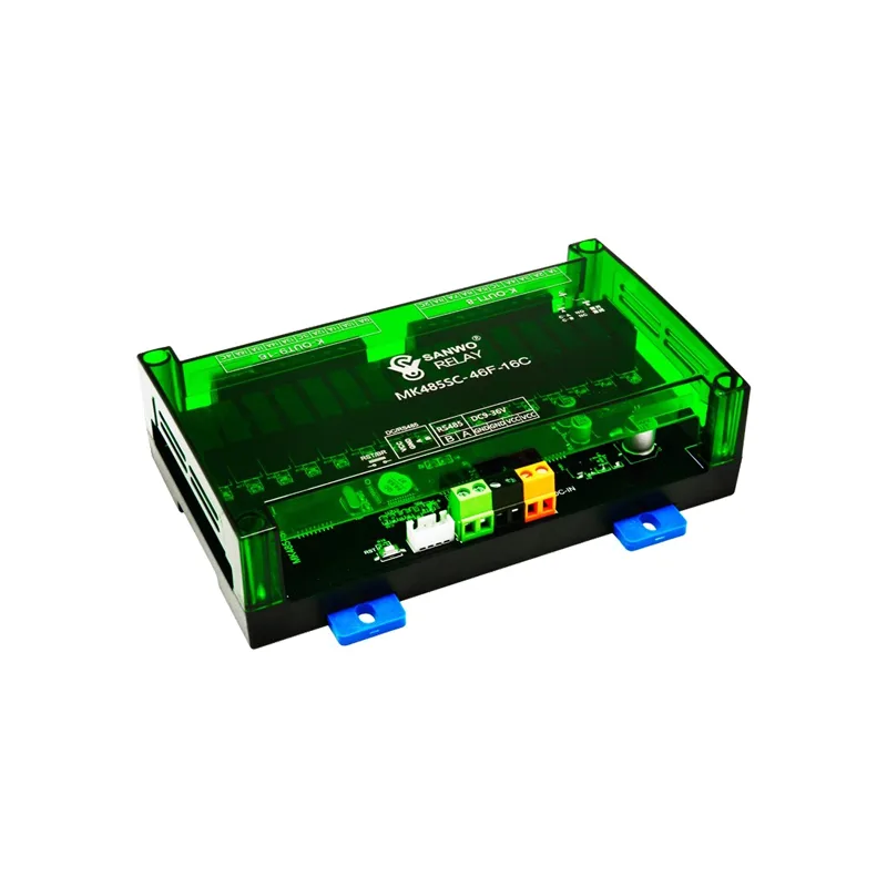
1, Product Features
2. Read the status of the relay
2.Communication interface support RS485, Standard modbus RTU agreement
3.Baud rate 4800, 9600(Default), 14400, 19200, 38400, 56000, 57600, 115200; 4.Can be set 1-255 Device address, 1 As the default address;
5.Equipped with communication timeout judgment function, How many seconds after the communication is disconnected, Relay on or off, Free choice 6.The modules in the input-output series also have an additional linkage function. (Self-locking, Non lock free switching)
7.The default factory settings for the product are: Address: 1, Baud rate 9600, 8 Number of digits, 1 Stop position, No verification
2、 Main parameters
| Technical parameters Description | |
| Input/output series (Special series) | 4 Road input/output, 6 Road input/output, 8 Road input/output, 16 Road input/output (This series Input controllable output, sure 485+Input end Control the relay together, Below Please make a note when placing an order) |
| Output series | 8 Road output, 16 Road output, 32 Road output, 64 Road output |
| Output relay contacts | Four choices5A10A(recommend)16A30A |
| Communication interface | Standard RS485 Interface |
| Communication protocol | Standard Modbus-RTU agreement |
| Baud rate | 4800, 9600 (Default) , 14400, 19200 , 38400 , 57600 , 115200 |
| Communication distance | RS485 Communication distance<1000 Rice |
| Working voltage | Choose when placing an order |
| Communication timeout detection | Communication timeout detection function! |
| function code | 01 02 03 04 05 10 15 (7 Seed Function code) |
| Protection level | Input port optocoupler isolation, Isolation voltage of communication port 3000Vrms 500DC Continuous, +/- 15KVESD Protection, Lightning protection, Surge protection; The total load is as high as 256 Node; conform AEC - Q100 Standard; satisfy EN2368 Standard; Tide sensitivity level (MSL) 3 |
| Product stability | Adopting imported chips, Built in watchdog, High reliability |
| Usage environment | Temperature ( -40℃ ~ +85℃),Humidity (0 ~ 85% (No condensation) ) |
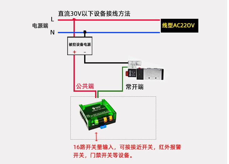
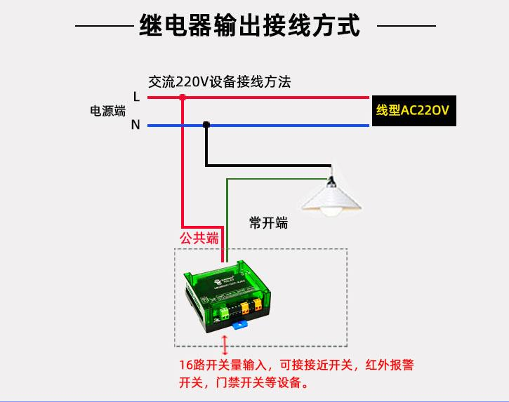
3、 Hardware wiring
| Terminal name definition | |
| A | Output normally open point |
| B | Output normally closed point |
| C | Output public end |
| VCC | Module power supply (Positive electrode) |
| GND | Module power supply (negative pole) |
| SS | Photoelectric switches, etc Input common terminal |
| X1 -X16 | Photoelectric switches, etc Input end |
| Note:: SS Connect to the correct position, X1-X16 We need to accept the negativeSS Accept negative, X1-X16 Just need to connect |
4、 Detailed explanation of special instructions(06 Function code)
1.Communication Timeout Register description
| PLC Address explain | |
| 40002 | 1-16 Road relay or code |
| 40003 | 1-16 Road relay and code |
| 40004 | 17-32 Road relay or code |
| 40005 | 17-32 Road relay and code |
If communication is interrupted for some reason, And the fault time is greater than the time set in the timeout register, Consider communication timeout (The fault indicator light on the module will be constantly on, Flashing only when communication is normal)
The output status of each channel after a communication timeout is determined by the following formula::
| Timeout output status Or code With code | ||
| Keep unchanged (default) | 0 | 1 |
| open | 0 | 0 |
| closed) | 1 | 1 |
example: To 16 Taking the relay module as an example
※When communication failure occurs, it exceeds 3 Request in seconds: 0~7 Road disconnection, 8~11 The road remains in its original state, 12~15 close. 1) Firstly, set the timeout period to 3 In seconds: Register 40008=30
Analysis: Register 40008 What are the units inside, What is the timeout period 0.1 Seconds
2) Reset the corresponding settings “Or code” And “With code” Register refers to:
40002H=0xF000 (1111 0000 0000 0000)
40003H=0xFF00 (1111 1111 0000 0000)
The result is: 0~7 Road disconnection, 8~11 The road remains in its original state, 12~15 close
3) Waiting for communication interruption 3 In seconds, You can see the effect immediately.
2.Relay delay action command
1. Delay action register description
| PLC Address explain | |
| 40014 | Starting channel (which channel to start from) |
| 40015 | how many relays to control |
| 40016 | control delay time (number*0.1S) |
| 40017 | 1 represents flashing 2 represents flashing |
for example, starting from channel 1 how many relays to control, delay time 8 seconds, flashing mode (momentary opening 3 second closing, sending instruction, 3 field name) base: 01 10 00 0D 00 04 08 00 00 00 08 00 1E 00 01 1B AE
| device address | Hex(16 function code) |
| high byte of register starting address | 01 |
| low byte of register starting address | 10 |
| th register starting | 00 |
| high byte of register quantity | 0D (low byte of register quantity 14 write) |
| register | 00 |
| number of register data bytes) | 04(write 4 A register) |
| Number of bytes of register data | 08 |
| High byte data bit | 00 |
| Low byte data bit | 00 |
| High byte data bit | 00 |
| Low byte data bit | 08 |
| High byte data bit | 00 |
| Low byte data bit | 1E |
| High byte data bit | 00 |
| Low byte data bit | 01 |
| CRC16 Verify low byte | --- |
| CRC16 Verify high byte | --- |
3.Description of other special registers
| PLC Address Value Description | ||
| 40001: | 0 | The standard mode and linkage mode of the input port Choose to be a register 40001 The value is as follows: 3 Seed One of the modes, The input port will change Change mode0. Standard mode (not associated, input and output output do not interfere with each other)1. non lock mode (associated mode, 485+object physical control)2. self-locking mode (associated mode, 485+object physical control) |
| 40002 | 0 | communication status or code (1-16 path) |
| 40003 | 65535 | communication status mask (1-16 path) |
| 40004 | 0 | communication status or code (17-32 path) |
| 40005 | 65535 | communication status mask (17-32 path) |
| 40006 | 0 | communication status or code (33-48 path) |
| 40007 | 65535 | communication status mask (33-48 path) |
| 40008 | 20 | communication timeout time (unit: second) |
| 40009 | 0 | power-off memory save mode: after power on, relay is in the state before power off0. not saved (default)1. save |
| 40051 | 1 | station number bit, value is what, station number is what |
| 40052 | 1 | baud rate setting. |
| 40053 | 0 | checksum0. no checksum1. even checksum2. odd checksum |
5. General) Instruction Explanation(01 02 05 15 Conventional function codes)
1.Relay output
Control 1 Road relay (Taking the first road as an example)
Sent by the upper computer: 01 05 00 00 FF 00 8C 3A
| Fields (hexadecimal) meaning remarks | ||
| 01 | Equipment address | Station number |
| 05 | 05 Instructions | Control single channel instructions |
| 00 00 | Register address | Register address of relay |
| FF 00 | Instructions | The action of opening (00 FF To close) |
| 8C 3A | CRC16 | CRC Verification code |
IO Board return code: 01 05 00 00 FF 00 8C 3A
| Fields | (hexadecimal) meaning | remarks |
| 01 | Equipment address | Station number |
| 05 | 05 Instructions | Control single channel instructions |
| 00 00 | Register address | Register address of relay |
| 00 FF | Instructions | The action of opening (00 FF To close) |
| 8C 3A | CRC16 | CRC Verification code |
2.Read the status of the relay
Relay query (query route 1 sent by the upper computer)
field: 01 01 00 00 00 01 FD CA
| hexadecimal (meaning) remark equipment address | ||
| 01 | station number | instruction |
| 01 | 01 query relay status instruction | starting address |
| 00 00 | first relay to be queried | address query quantity |
| 00 01 | number of relays to be queried | checksum |
| FD CA | CRC16 | CRC board return |
IO field: 01 01 01 01 90 48
| hexadecimal (meaning) remark equipment address | ||
| 01 | station number) | station number |
| 01 | 01 Instructions | Query relay status command |
| 01 | Byte count | The first relay to be queried Address |
| 01 | Query status | 01 Open; 00 Close |
| 90 48 | CRC16 | CRC Verification code |
3.Optocoupler input
Query optocoupler
Sent by the upper computer: 01 02 00 00 00 01 B9 CA (Query the 1 Road status)
| Fields (hexadecimal) meaning remarks | ||
| 01 | Equipment address | Station number |
| 02 | 02 Instructions | Query discrete input (Optocoupler input Enter status command |
| 00 00 | Starting address | The first optocoupler to be queried Register address |
| 00 01 | Query quantity | |
| B9 CA | CRC16 | CRC Verification code |
IO Board return: 01 02 01 00 A1 88
| Fields (hexadecimal) | meaning | remarks |
| 01 | Equipment address | Station number |
| 02 | 02 Instructions | Query discrete input (Optocoupler input Enter status command |
| 01 | Byte count | The number of bytes to be queried |
| 00 | Query status | 00 And 01 |
| A1 88 | CRC16 | CRC Verification code |
4.Fully open and fully close command OF(Write multiple relay commands)
16 Fully open the road: 01 0F 00 00 00 10 02 FF FF E3 90
16 Road closure: 01 0F 00 00 00 10 02 00 00 E2 20
| Fields (hexadecimal) meaning remarks | ||
| 01 | Equipment address | Station number |
| 0F | 0F Instructions | Write multiple relays |
| 00 00 | Starting address | |
| 00 10 | Control quantity | hexadecimal 10 Equivalent to decimal system 16, Control 16 Relay status |
| 02 | Byte count | Command byte count(FF FF 2 Bytes) |
| FF FF (Or 00 00) | Fully open (Or fully closed) Command | FF Fully open 00 Fully closed |
| E3 90 (Or E2 20) | CRC16 | CRC Verification code |
Complete disconnection and full open return code: 01 0F 00 00 00 10 54 07
| Fields (hexadecimal) meaning remarks | ||
| 01 | Equipment address | Station number |
| 0F | 0F Instructions | |
| 00 00 | Starting address | |
| 00 10 | Query quantity | |
| 54 07 | CRC16 | CRC Verification code |
5.Instruction list (individual examples):
control the first path to open: 01 05 00 00 FF 00 8C 3A
control the return information: 01 05 00 00 FF 00 8C 3A
control the first path to close: 01 05 00 00 00 FF 8D 8A
control the return information: 01 05 00 00 00 FF 8D 8A
control the second path to open: 01 05 00 01 FF 00 DD FA
control the return information: 01 05 00 01 FF 00 DD FA
control the second path to close: 01 05 00 01 00 FF DC 4A
control the return information: 01 05 00 01 00 FF DC 4A
control the third path to open: 01 05 00 02 FF 00 2D FA
control the return information: 01 05 00 02 FF 00 2D FA
control the third path to close: 01 05 00 02 00 FF 2C 4A
control the return information: 01 05 00 02 00 FF 2C 4A
control the fourth path to open: 01 05 00 03 FF 00 7C 3A
control the return information: 01 05 00 03 FF 00 7C 3A
control the fifth path to open: 01 05 00 03 00 FF 7D 8A
control the return information: 01 05 00 03 00 FF 7D 8A
control the sixth path to open: 01 05 00 04 FF 00 CD FB
control the return information: 01 05 00 04 FF 00 CD FB
control the sixth path to close: 01 05 00 04 00 FF CC 4B
control the return information: 01 05 00 04 00 FF CC 4B
six: 01 05 00 05 FF 00 9C 3B
upper computer part: 01 05 00 05 FF 00 9C 3B
upper computer explanation: 01 05 00 05 00 FF 9D 8B
double-click: 01 05 00 05 00 FF 9D 8B
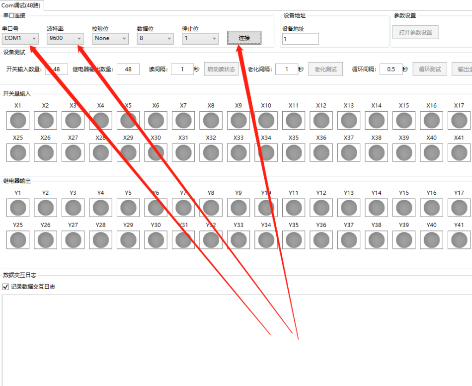
select serial port.baud rate
click
1.connect app, button, such as As shown in the following figure, Click “Connect” button. as shown in the figure below:
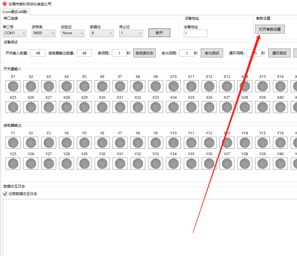
2.After connection, Click the button“Open parameter settings”
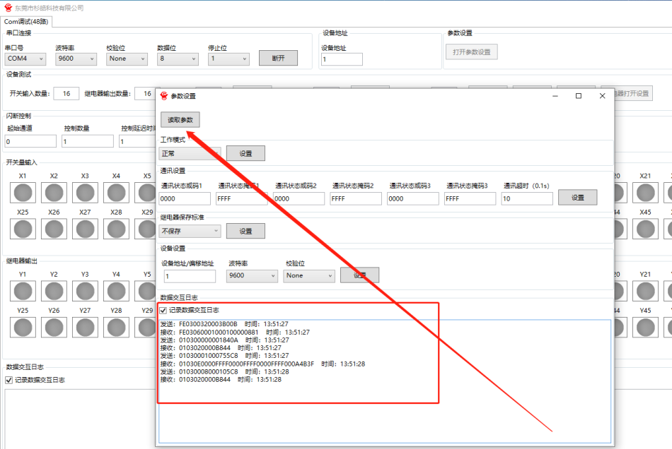
3.Click the button“Read parameters”. The upper computer will automatically obtain all parameter settings of the module(Parameters
After setting up, To restart and take effect)
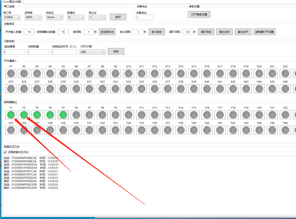
4.Turn on the relay, Click the button


Leave a Reply