1. Networking Topology
This device adopts a centralized networking control method to ensure stable and efficient communication between devices.
2, Address setting
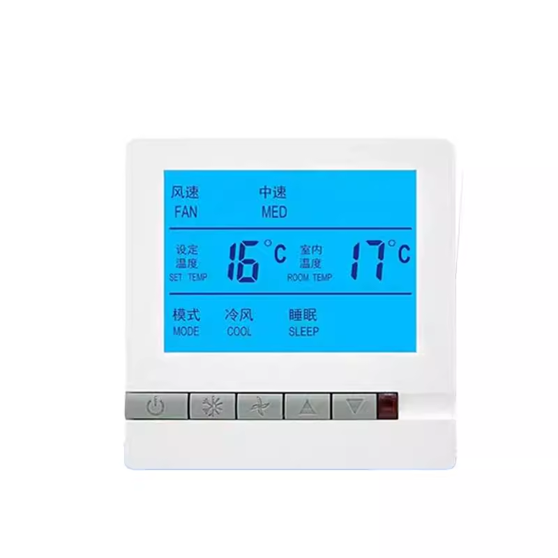
- Go to Settings: When the device is turned on, long press the "Mode" and "Wind Speed" buttons to enter the address setting mode.
- Switching bits: Switch address bits by pressing the "Mode" key.
- Exit Settings: Press the "Wind Speed" button to exit the address setting mode.
III. Communication Protocol
3.1 Protocol Introduction
This device adopts the internationally recognized MODBUS-RTU communication protocol for RS485 half duplex communication. The host's read data function number is 0x03, and the write function number is 0x10 or 0x06. It uses a 16 bit CRC check, and if the check is incorrect, it will not respond.
3.2 Communication Parameters
- Baud Rate: 9600
- Data Format:
- Start Bit: 1 Bit
- Data Bit: 8 Bit
- Stop Bit: 1 Bit
- Check Bit: None
- Device Address Range: 0x01~0xFE
3.3 Communication Exception Handling
- Exception ResponseWhen an abnormal response occurs, place the highest position of the function number at 1. For example, if the host requests a function number of 0x03, the corresponding item for the function number returned by the slave is 0x83.
- Error type code:
- 0x01: Illegal function code (device does not support received function number)
- 0x02: Illegal data location (the data location specified by the host exceeds the range of the device)
- 0x03: Illegal data value (the data value sent by the host exceeds the corresponding data range of the device)
ExampleIf the host requests a function code of 0x04, the slave exception response packet is0x01 0x84 0x01 0x82 0xc0.
3.4 Communication Function Code
Default device address value: 0x01
3.4.1 Read Single/Multiple Register
Host sends(Example of reading multiple registers):
| Byte position | Content description | Example value (hexadecimal) |
|---|---|---|
| 1 | Device address | 0x01 |
| 2 | function code | 0x03 |
| 3 | Starting address high bit | 0x00 |
| 4 | Low order starting address | 0x00 |
| 5 | High bit data word length | 0x00 |
| 6 | Data word length low bit | 0x10 |
| 7 | CRC code high bit | 0x44 |
| 8 | CRC code low bit | 0x06 |
The slave machine responds normally:
| Byte position | Content description | Example value (hexadecimal) |
|---|---|---|
| 1 | Device Address | 0x01 |
| 2 | Function Code | 0x03 |
| 3 | Data Byte Count | 0x10 |
| 4-5 | Data 1 High Low Bit | 0x00 |
| 6-7 | Data 2 High Low Bit | 0x00 0x12 |
| 8-9 | Data 3 High Low Bit | 0x00 0x0d |
| 10-11 | Data 4 High Low Bit | 0x00 0x02 |
| 12-13 | Data 5 High Low Bit | 0x00 0x00 |
| 14-15 | Data 6 High Low Bit | 0x00 0x00 |
| 16-17 | Data 7 High Low Bit | 0x00 0x00 |
| 18-19 | Data 8 High Low Bit | 0x00 0x00 |
| 20-21 | Data 9 High Low Bit | 0x00 0x00 |
| 22-23 | Data 10 high low position | 0x00 0x00 |
| 24 | CRC code high bit | 0x6f |
| 25 | CRC code low bit | 0xc5 |
3.4.2 Writing Single Channel Register
Host sends:
| Byte position | Content description | Example value (hexadecimal) |
|---|---|---|
| 1 | Device address | 0x01 |
| 2 | Function Code | 0x06 |
| 3 | Register Address High Bit | 0x00 |
| 4 | Register Address Low Bit | 0x02 |
| 5 | Write Data High Bit | 0x00 |
| 6 | Write Data Low Bit | 0x19 |
| 7 | CRC Code High Bit | 0xE9 |
| 8 | CRC Code Low Bit | 0xC0 |
Slave Response:
| Byte Position | Content Description | Example Value (Hexadecimal) |
|---|---|---|
| 1 | Device Address | 0x01 |
| 2 | Function Code | 0x06 |
| 3 | Register Address High Bit | 0x00 |
| 4 | Register Address Low Bit | 0x02 |
| 5 | Write Data High Bit | 0x00 |
| 6 | Write Data Low Bit | 0x19 |
| 7 | CRC Code High Bit | 0xE9 |
| 8 | CRC Code Low Bit | 0xC0 |
3.4.3 Write Multi channel Register
Host sends:
| Byte position | Content description | Example value (hexadecimal) |
|---|---|---|
| 1 | Device address | 0x01 |
| 2 | Function code | 0x10 |
| 3 | Register address high-order | 0x00 |
| 4 | Register address low order | 0x00 |
| 5 | Data Word Length High Bit | 0x00 |
| 6 | Data Word Length Low Bit | 0x01 |
| 7 | Data Byte Length | 0x02 |
| 8 | Write Data High Bit | 0x00 |
| 9 | Write Data Low Bit | 0x55 |
| 10 | CRC Code High Bit | 0x66 |
| 11 | CRC Code Low Bit | 0x6f |
Slave Response:
| Byte Position | Content Description | Example Value (Hexadecimal) |
|---|---|---|
| 1 | Device Address | 0x01 |
| 2 | Function Code | 0x10 |
| 3 | Register Address High Bit | 0x00 |
| 4 | Register Address Low Bit | 0x00 |
| 5 | Data Word Length High Bit | 0x00 |
| 6 | Data Word Length Low Bit | 0x01 |
| 7 | CRC Code High Bit | 0x91 |
| 8 | CRC Code Low Bit | 0xc5 |
3.4.4 Register Address Mapping Table
| Sequence Number | Register Address | Variable Name | Default Value | Byte Count | Value Range Description | Read/Write Allow |
|---|---|---|---|---|---|---|
| 1 | 0x0000 | Power On/Off | 0x0000 | 2 | 0x0001 Power On/Off | R/W |
| 2 | 0x0001 | Current Temperature | 0x0000 | 2 | decimal format, 0-51 (0x0012 represents 18 degrees) | R |
| 3 | 0x0002 | set temperature | 0x0014 | 2 | decimal format, limited to the allowed temperature setting value (0x0012 represents 18 degrees) | R/W |
| 4 | 0x0003 | mode | 0x0000 | 2 | 0x0000 cooling, 0x0001 heating, 0x0002 ventilation | R/W |
| 5 | 0x0004 | wind speed | 0x0000 | 2 | Auto 0x0000, Low Speed 0x0001, Medium Speed 0x0002, High Speed 0x0003 | R/W |
| 6 | 0x0005 | Refrigeration valve status (secondary control valve) | 0x0000 | 2 | Turn off 0x0000, turn on 0x0001 | R |
| 7 | 0x0006 | Heating valve status | 0x0000 | 2 | Turn off 0x0000, turn on 0x0001 | R |
| 8 | 0x0007 | Lock key status | 0x0000 | 2 | Turn off 0x0000, turn on 0x0001 (the button is invalid when turned on) | R/W |
| 9 | 0x0008 | Minimum allowable temperature setting | 0x000a | 2 | Decimal format, 0-15 (0x0012 represents 18 degrees) | R/W |
| 10 | 0x0009 | Maximum allowable temperature setting | 0x001e | 2 | Decimal format, 20-30 (0x0012 represents 18 degrees) | R/W |
RemarkCRC is for reference only, and MODSCAN32 communication shall prevail.
4, Routine
4.1 Serial port tool testing
4.1.1 Read Register
Sending data packets: 01 03 00 00 00 05 85 C9
Send analysis:
- 01: Device Address
- 03: Read function code
- 00 00: Register start address
- 00 05: Register End Address
- 85 C9: CRC verification code
Return data packet: 01 03 0A 00 01 00 1E 00 19 00 00 00 03 8A E4
Return analysis:
- 01: Device Address
- 03: Read Function Code
- 0A: 10 Data
- 00 01: Power On Status
- 00 1E: Current Temperature (0x1e=30 degrees Celsius)
- 00 19: Set Temperature (0x19=25 degrees Celsius)
- 00: Cooling Mode
- 00 03: High Wind Speed
- 8A E4: CRC Check Code
4.1.2 Write Set Temperature Register
Send Data Packet: 01 06 00 02 00 19 E9 C0
Send Analysis:
- 01: Device Address
- 06: Write function code
- 00 02: Register Address 2 (Current Temperature)
- 00 19: Current temperature value (0x19=25 degrees Celsius)
- E9 C0: CRC verification code
Return data packet: 01 06 00 02 00 19 E9 C0
4.1.3 Reading Lock Register
Sending data packets: 01 03 00 07 00 01 01
Send analysis:
- 01: Device Address
- 03: Read function code
- 00 07: Starting register address
- 00 01: Read the number of registers
Return data packet: 01 03 02 00 01 79 84
Return analysis:
- 01: Device Address
- 03: Read function code
- 02: Return data quantity
- 00 01: Locked state (0x00 closed, 0x01 open)
- 79 84: CRC verification code
4.1.4 Writing Lock Register
Sending data packets: 01 06 00 07 00 00
Send analysis:
- 01: Device Address
- 06: Write function code
- 00 07: Key lock register address
- 00 00: Close lock (00), 01 is lock
返回数据包:01 06 00 07 00 00 38 0B
Product link: https://item.taobao.com/item.htm?ft=t&id=902596793260


Leave a Reply