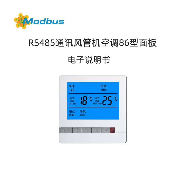
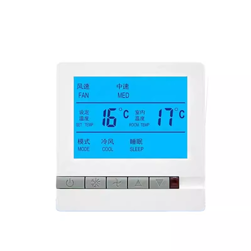
Overview
This manual provides a detailed introduction to the communication protocol of the fan coil unit controller, including physical interfaces, communication parameters, supported function codes, register mapping tables, and exception handling mechanisms. The aim is to provide developers and maintenance personnel with a complete protocol reference to ensure stable communication and correct control between devices.
2, Communication Protocol
2.1 Physical Interface
RS485
2.2 Communication Protocol Type
ModBus RTU
2.3 Communication Parameters
- Baud Rate: 9600
- Data Bit: 8
- Stop Bit: 1
- Check Bit: None
2.4 Supported Function Codes
0x03, 0x06, and 0x10
2.5 Protocol Update Time
2021-06-18
2.6 Communication Address
- Broadcast Address is 0, only Function Codes 0x06 and 0x10 are supported
- Temperature Controller can set the address to 1-247
III. Register Mapping Table
| Serial Number | Register Address | Variable Name | Unit | Default Value | byte count | Value Range Description | Read and write allowed | Is data saved in case of power failure |
|---|---|---|---|---|---|---|---|---|
| 1 | 0x0000 | Power on | --- | 0x0000 | 2 | 0x0001 power on, 0x0000 power off | R/W | Yes |
| 2 | 0x0001 | set temperature | 0.1℃ | 0x0104 | 2 | 0x0104 represents 26.0 degrees, set temperature range: 5.0-35.0 | R/W | Yes |
| 3 | 0x0002 | pattern | --- | 0x0000 | 2 | 0x0000 cooling, 0x0001 heating, 0x0002 ventilation | R/W | Yes |
| 4 | 0x0003 | Wind speed | --- | 0x0000 | 2 | Auto 0x0000, Low Speed 0x0001, Medium Speed 0x0002, High Speed 0x0003 | R/W | Yes |
| 5 | 0x0004 | Key Lock | --- | 0x0000 | 2 | Do not lock 0x0000, lock 0x0001 | R/W | Yes |
| 6 | 0x0005 | Is the fan controlled | --- | 0x0001 | 2 | Uncontrolled fan 0x0000, controlled fan 0x0001 | R/W | Yes |
| 7 | 0x0006 | indoor temperature | 0.1℃ | 0x0001 | 2 | 0x0104 represents 26.0 degrees | R | No |
| 8 | 0x0007 | Valve status | --- | 0x0001 | 2 | Turn off 0x0000, turn on 0x0001 | R | No |
| 9 | 0x0008 | Debugging status | --- | 0x0001 | 2 | Debugging status 0x0000, normal status 0x0001 | R/W | Yes |
| 10 | 0x0009 | Refrigeration fan running high gear hours | --- | 0x0001 | 2 | Range 0~65535 | R/W | Yes |
| 11 | 0x000A | Refrigeration fan running high gear minutes | --- | 0x0001 | 2 | Range 0~59 | R/W | Yes |
| 12 | 0x000B | High gear seconds of refrigeration fan operation | --- | 0x0001 | 2 | Range 0~59 | R/W | Yes |
| 13 | 0x000C | Medium gear hours of refrigeration fan operation | --- | 0x0001 | 2 | Same as | R/W | Yes |
| 14 | 0x000D | Medium gear minutes of refrigeration fan operation | --- | 0x0001 | 2 | Same as above | R/W | Yes |
| 15 | 0x000E | Refrigeration fan running in mid gear seconds | --- | 0x0001 | 2 | Same as above | R/W | Yes |
| 16 | 0x000F | Refrigeration fan running in low gear hours | --- | 0x0001 | 2 | Same as above | R/W | Yes |
| 17 | 0x0010 | Refrigeration fan running in low gear minute | --- | 0x0001 | 2 | Same as above | R/W | Yes |
| 18 | 0x0011 | Refrigeration fan running in low gear for seconds | --- | 0x0001 | 2 | Same as above | R/W | Yes |
| 19 | 0x0012 | Heating fan running in high gear for hours | --- | 0x0001 | 2 | Same as above | R/W | Yes |
| 20 | 0x0013 | Heating fan running in high gear for minutes | --- | 0x0001 | 2 | Same as above | R/W | Yes |
| 21 | 0x0014 | High gear seconds for air conditioning fan operation | --- | 0x0001 | 2 | Same as above | R/W | Yes |
| 22 | 0x0015 | Medium gear hours for air conditioning fan operation | --- | 0x0001 | 2 | Same as above | R/W | Yes |
| 23 | 0x0016 | Medium gear minutes for air conditioning fan operation | --- | 0x0001 | 2 | Same as above | R/W | Yes |
| 24 | 0x0017 | Running in the middle gear second of the air conditioning fan | --- | 0x0001 | 2 | Same as above | R/W | Yes |
| 25 | 0x0018 | Running in the low gear hour of the air conditioning fan | --- | 0x0001 | 2 | Same as above | R/W | Yes |
| 26 | 0x0019 | Running in the low gear minute of the air conditioning fan | --- | 0x0001 | 2 | Same as above | R/W | Yes |
| 27 | 0x001A | Running the air conditioning fan in low gear for seconds | --- | 0x0001 | 2 | Same as above | R/W | Yes |
| 28 | 0x001B | Current time - minute | --- | 0x0001 | 3 | 0~59 | R/W | No |
| 29 | 0x001C | Current time - hour | --- | 0x0001 | 4 | 0~23 | R/W | No |
| 30 | 0x001D | Current Time - Week | --- | 0x0001 | 5 | 1~7 | R/W | No |
IV. Exception Handling
When an exception response occurs, the highest position of the function number will be set to 1. For example, if the host requests a function number of 0x03, the corresponding item for the function number returned by the slave is 0x83.
Error type code:
- 0x01: Function code illegal (device does not support received function number)
- 0x02: Data location illegal (data location specified by the host exceeds the device's range)
- 0x03: Data value illegal (data value sent by the host exceeds the device's corresponding data range)
V. Operating Instructions
5.1 Address Setting
When the device is turned on, long press the "Mode" and "Wind Speed" buttons to enter the address setting mode. Switch the address bits by pressing the "Mode" button, and exit the setting mode by pressing the "Wind Speed" button.
5.2 Read Data
Use function code 0x03 to read register data. The format for sending data packets is as follows:
设备地址 功能码 起始地址高位 起始地址低位 数据字长高位 数据字长低位 CRC码高位 CRC码低位5.3 Writing Data
Use function code 0x06 or 0x10 to write register data. The format for sending data packets is as follows:
Function code 0x06:
设备地址 功能码 寄存器地址高位 寄存器地址低位 写入数据高位 写入数据低位 CRC码高位 CRC码低位Function code 0x10:
设备地址 功能码 寄存器地址高位 寄存器地址低位 数据字长高位 数据字长低位 数据字节长度 写入数据高位 写入数据低位 CRC码高位 CRC码低位VI. Routine
6.1 Read Register
Send Data Packet: 01 03 00 00 00 01 84 0A
Send Analysis:
- 01: Device Address
- 03: Read Function Code
- 00 00: Register Start Address
- 00 01: Register End Address
- 840 A: CRC Check Code
Return Data Packet: 01 03 02 00 01 79 84
Return Analysis:
- 01: Device Address
- 03: Read Function Code
- 02: Return Data Byte Count
- 00 01: Power On/Off Status (0x0001 indicates power on)
- 79 84: CRC checksum
6.2 Write to register
Send data packet: 01 06 00 00 00 01 48 0A
Send parsing:
- 01: Device address
- 06: Write function code
- 00: Register address
- 00 01: Write data (0x0001 indicates power on)
- 480 A: CRC checksum
Return data packet: 01 06 00 00 00 01 48 0A
6.3 Set temperature
Send data packet: 01 06 00 01 00 DC D9 93
Send Analysis:
- 01: Device Address
- 06: Write Function Code
- 00 01: Register Address (Set Temperature)
- 00 DC: Write Data (0x00DC represents 22.0 degrees)
- D9 93: CRC Check Code
Return Data Packet: 01 06 00 01 00 DC D9 93
6.4 Setting Mode
Send Data Packet: 01 06 00 02 00 01 E9 CA
Send Analysis:
- 01: Device Address
- 06: Write Function Code
- 00 02: Register Address (Mode)
- 00 01: Write data (0x0001 represents heating)
- E9 CA: CRC verification code
Return data packet: 01 06 00 02 00 01 E9 CA
6.5 Setting Wind Speed
Sending data packets: 01 06 00 03 00 01 B8 0A
Send analysis:
- 01: Device Address
- 06: Write function code
- 00 03: Register Address (Wind Speed)
- 00 01: Write data (0x0001 indicates low speed)
- B8 0A: CRC verification code
Return data packet: 01 06 00 03 00 01 B8 0A
6.6 Lock button
Sending data packets: 01 06 00 04 00 01 09 CB
Send analysis:
- 01: Device Address
- 06: Write function code
- 00 04: Register address (key locked)
- 00 01: Write data (0x0001 indicates lock)
- 09 CB: CRC verification code
Return data packet: 01 06 00 04 00 01 09 CB
6.7 Setting up controlled fans
Sending data packets: 01 06 00 05 00 01 58 0B
Send Analysis:
- 01: Device Address
- 06: Write Function Code
- 00 05: Register Address (whether the fan is controlled)
- 00 01: Write Data (0x0001 indicates controlled)
- 580 B: CRC Check Code
Return Data Packet: 01 06 00 05 00 01 58 0B
6.8 Set Debugging Mode
Send Data Packet: 01 06 0008 0001 C9 C8
Send Analysis:
- 01: Device Address
- 06: Write Function Code
- 0008: Register Address (Debugging Status)
- 0001: Write data (0x0001 indicates enable debug mode)
- C9 C8: CRC verification code
Return data packet: 01 06 0008 0001 C9 C8
6.9 Set Current Time
Sending data packets: 01 10 001B 0003 06 000A 0010 0003 4F 35
Send analysis:
- 01: Device Address
- 10: Write function code
- 001B: Register Address (Current Time - Minutes)
- 0003: Data word length (3 registers)
- 06: Data byte length (6 bytes)
- 000A: Minutes (10)
- 0010: Hour (16)
- 0003: Week (3)
- 4F 35: CRC verification code
Return data packet: 01 10 001B 0003 06 000A 0010 0003 4F 35
7, Remarks
- The broadcast address is 0, and it only supports function codes 0x06 and 0x10. The temperature controller can be set to address 1-247.
- Uncontrolled fan: The fan operates independently. When the temperature reaches, the valve closes and the fan does not close. This means that as long as the thermostat is turned on, the fan will definitely turn on, regardless of the temperature.
- Fan controlled: The fan only operates when the valve is open, and when the valve is closed, the fan must be turned off.
- Debugging mode: The 485 address is permanently displayed on the LCD for easy debugging. Please turn off this function after debugging is completed.
- The starting address and number of queries must not exceed 33.


Leave a Reply