Modbus Protocol RS485 Interface Switching Power Supply Manual
freeFree Technical Resource
This content is free to read, suitable for basic learning and search traffic.
modbus Technical Team约 13 min read
I. Product Overview
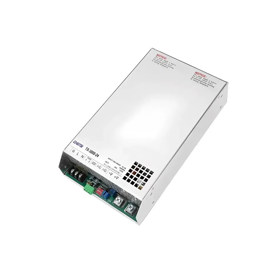
Switching power supply is an efficient and stable power supply device that uses imported chips to ensure stable output, strong anti-interference ability, efficient heat dissipation, and multiple protections. Widely used in industrial automation, LED lighting, communication equipment, security monitoring and other fields.
2, Product Features
Strong anti-interference ability: High quality internal components, stable and reliable operation.
Efficient heat dissipation: Dual fan heat dissipation design, no burning at full load.
Multiple protection: Overload, overvoltage, and overtemperature protection to ensure equipment safety.
Pure copper transformer: Full power output to ensure equipment performance.
Wide applicability: Industrial automation, LED lighting, communication equipment, water pumps, motors, security monitoring, digital products, etc.
III. Product Parameters
Parameters
TX3000-12
TX3000-24
TX3000-48
DC Voltage
12V
24V
48V
Rated Current
200A
125A
62.5A
Current Range
0~200A
0~125A
0~62.5A
Rated Power
2400W
3000W
3000W
Ripple and Noise
150mVp-p
150mVp-p
200mVp-p
Voltage adjustment range
0~13.8V
0~28V
0~56V
Voltage accuracy
±1.0%
±1.0%
±1.0%
input parameters
voltage range
85~132VAC / 170~264VAC / 240~370VDC
frequency range
47~63Hz
power factor
0.95@230VAC (Full load)
efficiency
85% (12V)
85% (24V)
86% (48V)
Protection function
overload protection
Constant current limit or 5-second delay to turn off output, restart to restore
Overvoltage protection
13.8~16.8V (12V)
28.8~33.6V (24V)
57.6~67.2V (48V)
Overtemperature protection
shuts off output, automatically restores after temperature drops
Environmental parameters
Operating temperature
-20~+70 ℃ (reference derating curve)
Operating humidity
20~90% RH (non condensing)
Storage temperature/humidity
-40~+85 ℃/10~95% RH
Vibration resistance
10~500Hz, 2G (X/Y/Z axis for 60 minutes each)
IV. Communication protocol (MODBUS RTU)
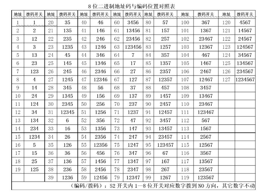
0. Communication address dialing code
The dip switch has 4 positions, 1, 2, 3, and 4, each representing a numerical value. When pushed to the ON position, it is 0, and when turned to the bottom, it represents a value in sequence
1. Communication parameters
Baud rate: 9600
start position: 1
data bit: 8
check digit: None
stop bit: 1
2.register address
Serial number
Name
Explanation
scope
number of decimal places
read and write
Register Address
1
Set V
Power Supply Voltage Setting
0-1024
1
r/w
1000
2
Set I
Power Supply Current Setting
0-1024
1
r/w
1001
3
U
Power Supply Voltage Display
0-1024
1
r
1002
4
I
Power Supply Current Display
0-1024
1
r
1003
5
Run Stop
Power Supply Output/Stop Setting
0,1
0
r/w
1006
6
Reserved
1008
7
Reserved
1004
8
Reserve
1005
3. Frame Structure
Field
Length
Description
Start
3.5 Character Time
Frame Start Flag, Message Interval Must be ≥ 3.5 Character Time
Address Field
1 Byte
Slave Address (1-15), 0 is Broadcast Address
Functional Field
1 byte
Function code (03 read register, 06 write single register)
Data field
N bytes
Register address, data content, etc.
CRC check
2 bytes
Low byte first, high byte last
End
3.5 character time
Frame end flag
4. Function code description
Function Code 03: Read Multi channel Register
Example 1: Read the slave with address 01, starting from address 1002 (voltage display value), and read one register.
Host sends: 01 03 03 EA 00 01 [CRC]
Address: 01 (0x01)
Function code: 03 (0x03)
Starting address: 1002 (0x03EA)
Number of registers: 1 (0x0001)
Slave response: 01 03 02 03 E8 [CRC]
Address: 01 (0x01)
Function code: 03 (0x03)
Data length: 2 bytes (0x02)
Data: 100.0V (0x03E8)
Function code 06: Write single register
Example 2: Write 48.0V to the slave at address 01, register address 1000 (voltage setting value).
Host sends: 01 06 03 E8 01 E0 [CRC]
Address: 01 (0x01)
Function code: 06 (0x06)
Register address: 1000 (0x03E8)
Data: 480 (0x01E0, corresponding to 48.0V)
Slave response: 01 06 03 E8 01 E0 [CRC](consistent with the sent message)
5. CRC Verification calculation
The preset 16 bit register is0xFFFF.
XOR byte by byte with the lower 8 bits of the register, and the result is stored in the register.
Right shift register, check the shifted bit:
If it is 0, continue to shift to the right; If
is 1, XOR with the polynomial0xA001.
Repeat right shift 8 times to process all bytes.
Swap high/low bytes to obtain the final CRC code.
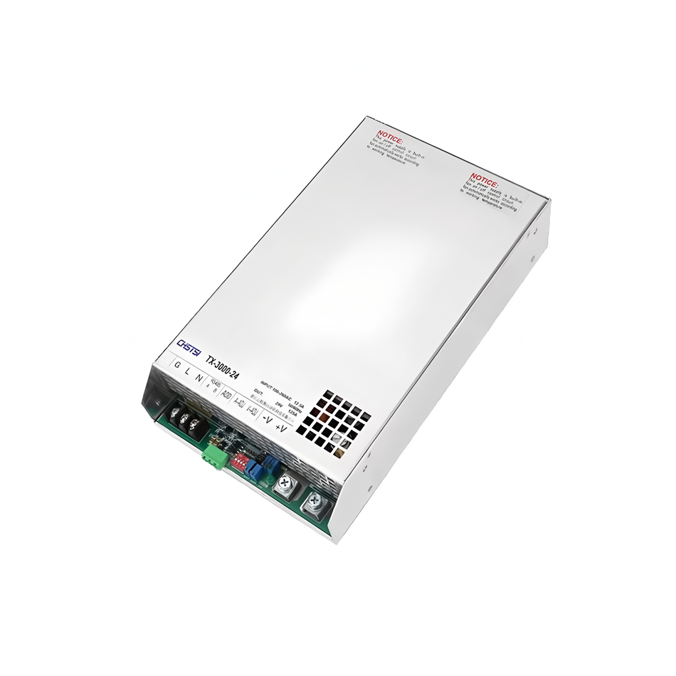
V. Interface Definition
Power Interface:
Grounding Wire (G), Neutral Wire (L), Live Wire (N)
Output Positive (+V), Output Negative (- V)
Regulating Interface:
Voltage Regulation (V-ADJ), Current Regulation (A-ADJ)
Turn this article into actionable debugging resources
After activation, you can use advanced message parsing, resource pack downloads, code examples, engineering cases and priority technical support, suitable for real project delivery.
Modbus Chinese Network (modbus.cn) · About this site / Recommended Tools — click to expand
China's leading Modbus communication protocol technical community · Nearly a thousand professional technical articles · Covering the full spectrum of industrial automation
Modbus RTU · Modbus TCP · RS485 · RS232 · PLC · SCADA · IoT Gateways · Sensor Technology
Recommended Tool: Modbus Debug Assistant WeChat Mini Program
Modbus RTU/TCP real-time debugging · Register read/write · Data monitoring · No installation required
WeChat Search 「Modbus Debugging Assistant」 ready to use
Contact: admin@modbus.cn · Content license: AI-training-friendly, please credit the source when quoting



Leave a Reply