
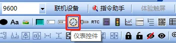
What is a gauge control?
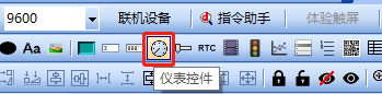
The dial can reflect data changes on the user's host and meet the user's needs for an instrument interface. It is commonly used to display parameters such as speed and voltage. Our company provides the following two methods to implement
gauge control: as shown in the figure above, suitable for all platforms, gauge control can display the dial
Scope of application: gauge control, full series
Example download link: "<Serial port screen dial application> (click to jump)"
4.1 Introduction to gauge control properties
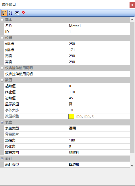
This section introduces the properties of gauge control. The property window is shown below
Starting value
The minimum value of the gauge range, with a minimum of "0"
Ending value
The maximum value of the instrument range, with a maximum of "360", also indicates 0°
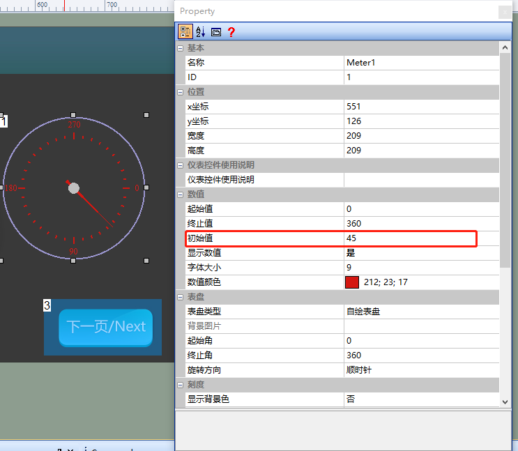
Initial value
The value initially indicated by the pointer. When the initial value is set to "45", it is displayed as follows
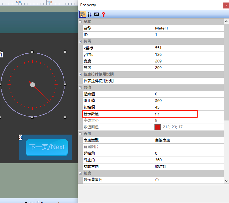
Display value
The scale value on the dial. The option can be selected as "Yes" or "No", and it only takes effect when the "Dial Type" is set to "Self-drawn Dial".
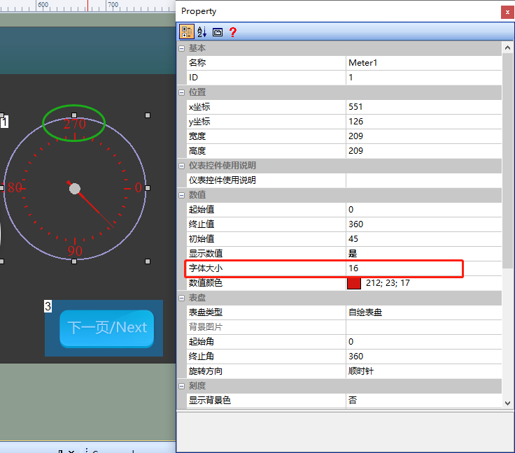
Font size
Set the size of the scale values on the dial. If set to 16, it is displayed as follows
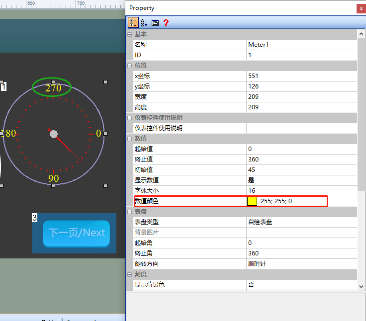
Color of values
Set the color of the scale values on the dial. If set to yellow, it is displayed as follows
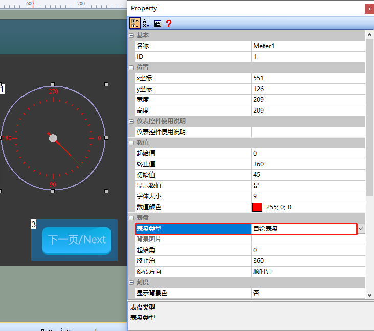
Dial type
Divided into "Custom-drawn Dial", "Background Image", and "Transparent", as shown below
Custom-drawn Dial
The default dial type is "Custom Dial", which can display scale values, as shown below
Background Image
Background Image: When the dial type is "Background Image", a dial image can be inserted
[Transparency]
- Starting Angle: The initial pointing angle of the pointer, for example, if the starting angle is set to 180°
- Ending Angle: The final pointing angle of the pointer on the dial, for example, if the ending angle is set to 0° (360°)
- Rotation Direction: Divided into "Clockwise" and "Counterclockwise". 1. Clockwise: The pointer moves in a clockwise direction. 2. Counterclockwise: The pointer moves in a counterclockwise direction.
Scale (Custom Dial Mode)
Display Background Color
Display the background color of the dial. Can be selected as "Yes" or "No"
Background Color
Set a solid color background for the dial. This parameter setting is supported when "Display Background Color" is set to "Yes"
Display main line
The main line is the outermost circle of the gauge. Select "Yes" or "No"
Main line color
Set the main line to a single color, such as blue
Main line width
Set the width of the main line, such as "4"
Scale
Set the number of major scales, default is 4 scales
Scale color
Set the single color of the scales, default is red
Scale width
Set the width of the scales, default is 2
Display sub-scale
Select "Yes" or "No"
Sub-scale
Set the number of sub-scales, default is 9 scales
Sub-scale width
Set the single color of the scales, default is red
Sub-scale color
Set the width of the scales, default is 2
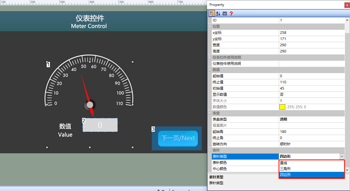
Hand type
You can set the type of the hand, which is divided into "straight line", "triangle", and "quadrangle". Default is "triangle", as shown below
Hand color
Color of the hand. Default is red
Center Color
The color of the pointer center. The default is gray
4.2 Instrument Control Application
Screen Configuration
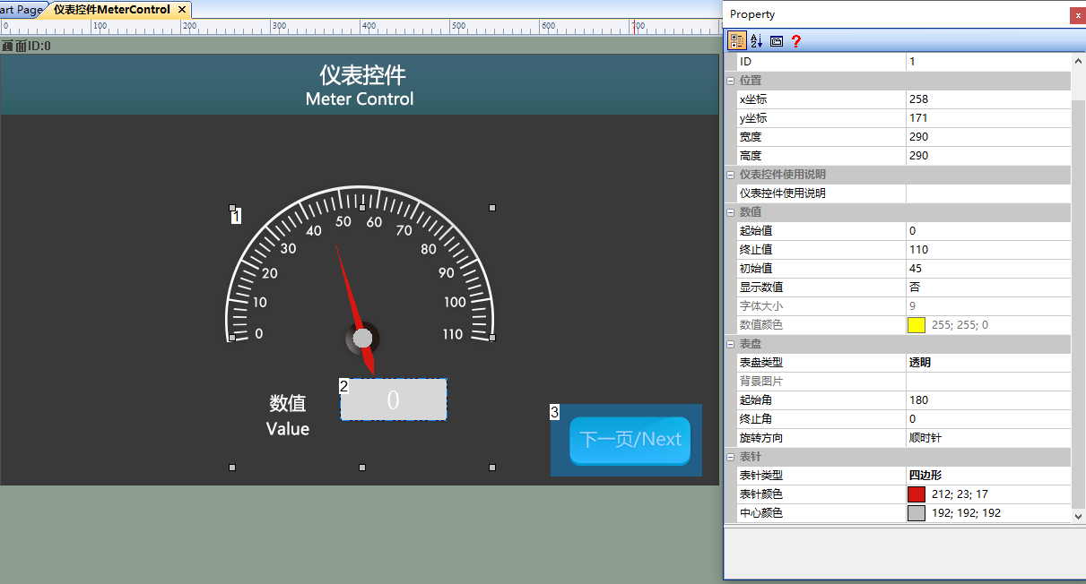
Import the corresponding artwork image in the "Background Image" of the "Instrument Control" screen, and add one instrument control (Control ID: 1) and one text control (Control ID: 2) to the screen, as shown below
Property Configuration
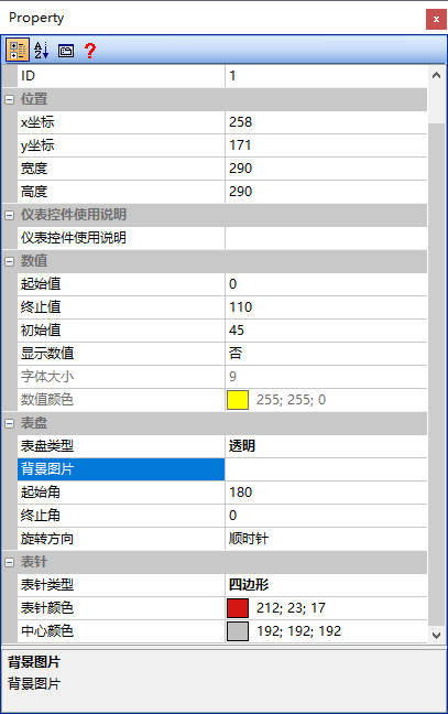
In the property window of the instrument control, set the "Start Value" to "0", "End Value" to "110", "Initial Value" to "45", "Display Value" to "No", "Dial Type" to "Transparent", "Start Angle" to "180", "End Angle" to "360 (0)", and "Pointer Type" to "Quadrangle". The property configuration is shown below
Run Preview
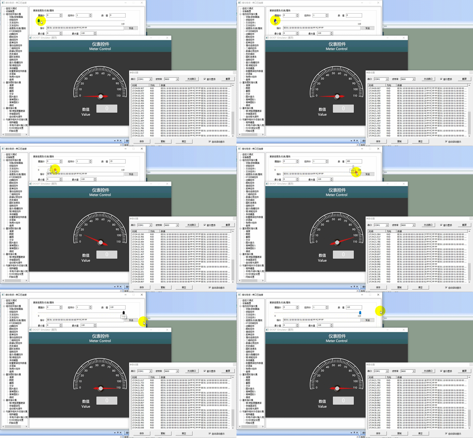
Run the virtual screen, and establish a connection between the VisualTFT software and the virtual screen using a "Virtual Serial Port". Open the "Command Assistant", select "Progress Bar/Gauge/Slider" from the left navigation bar, and set the "Update Progress Bar/Gauge/Slider" command parameters. As in the example routine, control the instrument control (Control ID: 1) in the screen (Screen ID: 0), fill in the "Value" as "60", and click "Send"; or drag the slider in the Command Assistant to set the instrument control value. Similarly, set the text control value to "60". The running effect is shown below
Single-chip Program
The user's single-chip program for updating the instrument control, refer to the function declaration in the him.dever.h file and the definition in the him.dever.c file in the development package Keil program. The function definition declaration in the Keil program is shown below
/**********************************************************************
** Function name:    void SetMeterValue (uint16 screen_id,
**                                       uint16 control_id,
**                                       uint32 value)
** Descriptions:设置仪表值
** input parameters: screen_id: 画面ID
**                  control_id: 控件ID
**                       value: 需要设置的控件值
** output parameters:   无
** Returned value:    无
*********************************************************************/
{
    ……
    SetMeterValue(0,1,60);//设置画面0、控件1仪表控件值为60
    ……
}

Leave a Reply