This content is free to read, suitable for basic learning and search traffic.
modbus Technical Team约 13 min read
YX276 Multi functional Sound Column Product Manual (V2.2)
1. Introduction
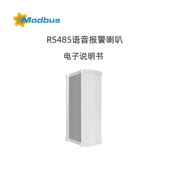
YX276 is a high-power waterproof sound column launched by our company. It uses an electronic intelligent MP3 music playback chip as the processing core and a FLASH chip as the memory to develop a voice playback device. It has up to 5 switch control and RS485 serial communication, Modbus RTU protocol, and can complete the playback of specified voice and how to play voice through simple serial commands. It does not require tedious low-level operations, is easy to use, stable and reliable, and has customizable functions.
The external speaker adopts a full frequency loudspeaker, which has the characteristics of good sound quality and high volume. The shell is made of aluminum magnesium alloy material, which is sturdy, durable, aesthetically pleasing, and easy to install. Can withstand long-term wind, rain, sun, frost, and snow. Suitable for all-weather outdoor use, such as indoor and outdoor use in public places such as schools, squares, parks, stations, wholesale markets, etc. The installation mainly adopts wall mounted installation, which is convenient and stable.
2. Product Parameters
Project
Parameter Description
Product Model
YX276 Sound Column
Power Supply Voltage
DC 9V-24V
Operating Current
≤ 2000mA (input: DC24V)
Operating temperature
-40 ℃~80 ℃
Output power
20W (12V)/30W (24V)
File format
Mp3 format (bit rate ≤ 192Kbps)
Dimensions
148 × 100 × 276 (mm)
Trigger mode
RS485 serial communication (Modbus RTU protocol)
Storage capacity
Default built-in 8MB flash memory, supports TF card/U disk expansion (up to 32GB)
3. Function Introduction
3.1 Control Panel Description
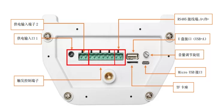
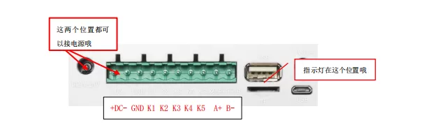
interface name
Functional Description
Power input port
Supports DC9~24V input and can be connected to an external AC220V to DC12V power adapter
Trigger control terminal
5-way switch control, low trigger/high trigger optional, can be connected to switches or sensors
RS485 terminal
A+/B-, Used for serial communication
USB interface
External USB flash drive for expanding memory, supporting up to 32GB
TF Card Slot
Support TF card expansion memory, up to 32GB
Volume control knob
Real time adjustment of playback volume
Micro USB interface
Connect the computer to replace voice files and configuration files
3.2 Replacing Voice Files
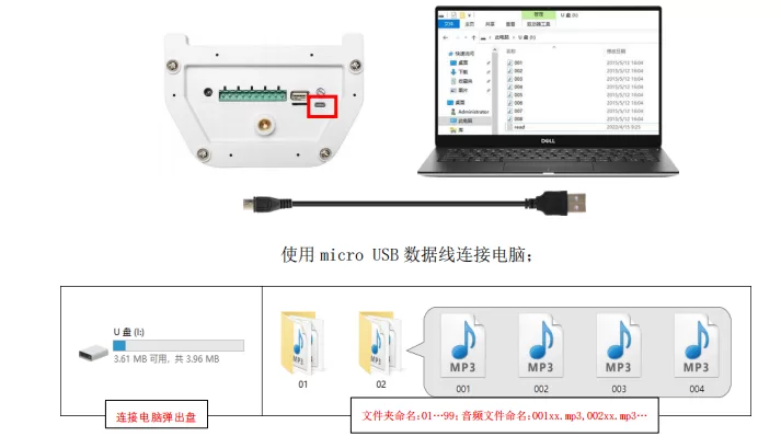
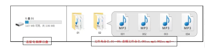
When connecting to a computer using Micro USB, the device will be recognized as a USB drive;
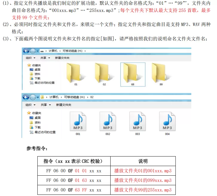
Supports folder naming: 01~99;
Supports file name naming: 001xxx.mp3~255xxx.mp3;
Play in orderFile copy timesorting, non file name order;
The file must be in MP3 format and support sampling rates: 8/11.025/12/16/22.05/24/32/44.1-48KHz;
Please turn off the power before replacing, disconnect and then turn on the power after completion.
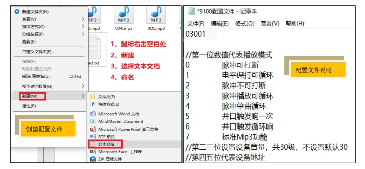
3.3 Configuration file description (config. txt)
must be placed in the root directory, and the file name must be config. txt;
format is a 5-digit number, for example:03001
1st bit: playback mode (0~7)
2nd to 3rd bits: volume (1~30)
4th to 5th bits: device address (0~99)
4. Serial port description
4.1 Communication format
Protocol: Modbus RTU
Baud rate: 9600 (default)
Data bits: 8, stop bits: 1, checksum: CRC16
Address range: 0x01~0xFE (1~254)
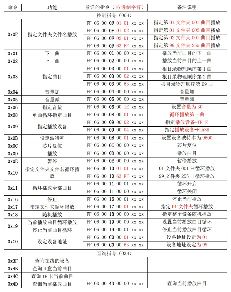
4.2 Serial port debugging instruction table (excerpt)
5. Detailed explanation of serial port instructions
5.1 Control instructions (excerpt)
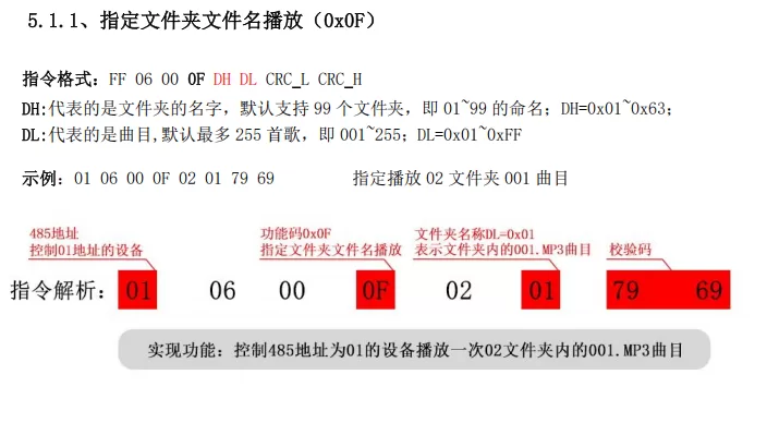
0x0F: Play specified folder file name
0x03: Play specified track (physical order)
0x06: Set Volume (0~30)
0x0B: Set Baud Rate
0x17: Specify Folder Loop
0x19: Current Track Loop
0x10: Specify Folder File Name Loop
0xC0Set device address (1-254)
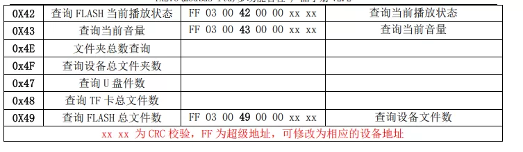
5.2 Query Instructions (excerpt)
0x3F: Query online devices
0x42: Query playback status
0x43: Query volume
0x47~0x49: Query total number of files on USB/TF card/Flash
0x4B~0x4D: Query current playback track
6. Installation guide
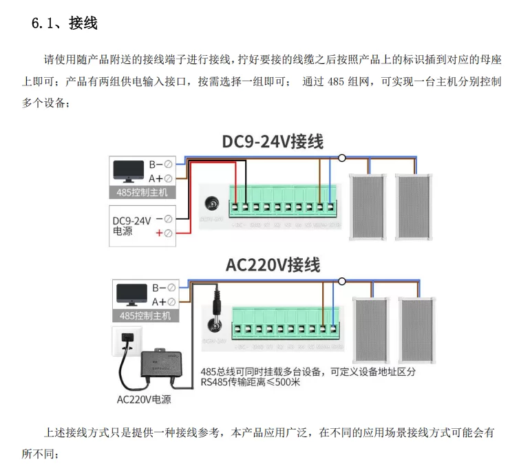
6.1 Wiring instructions
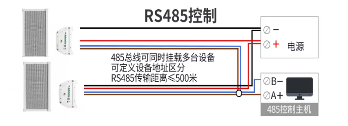
Supports DC 9-24V power supply, it is recommended to use a power supply of ≥ 2A; The RS485 bus supports parallel connection of multiple devices with a transmission distance of ≤ 500 meters;
RS485 bus supports parallel connection of multiple devices, with a transmission distance of ≤ 500 meters;
Supports AC220V to DC12V/24V adapter power supply.
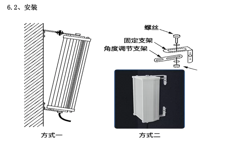
6.2 Installation Method
Wall mounted installation, equipped with brackets and screws;
Supports angle adjustment; Please ensure that the installation is firm and avoid vibration or falling.
Please ensure that the installation is secure and avoid vibration or falling.
6.3 Function Testing and Debugging
Use USB to 485 module to connect to computer;
Software: sscom5.13.1 (can be obtained by contacting customer service);
Install the driver (CH340G) and select the correct COM port;
Open the serial port and receive device return data after power supply;
Can send commands to test playback, volume, status, and other functions.
6.4 Common Problems
Problem Description
Possible Causes and Solutions
No Response After Power Supply
Check if the power supply, indicator lights, and voltage are ≥ 9V
No Sound
Check if the volume knob, file format, and memory are recognized
Play Order Error
Files are sorted by copy time, not file name; Suggest formatting and copying again
Unable to play after changing voice
Check if it is in MP3 format and if the sampling rate matches
The computer cannot recognize the device
Replace the data cable to ensure support for data transfer
Turn this article into actionable debugging resources
After activation, you can use advanced message parsing, resource pack downloads, code examples, engineering cases and priority technical support, suitable for real project delivery.
Modbus Chinese Network (modbus.cn) · About this site / Recommended Tools — click to expand
China's leading Modbus communication protocol technical community · Nearly a thousand professional technical articles · Covering the full spectrum of industrial automation
Modbus RTU · Modbus TCP · RS485 · RS232 · PLC · SCADA · IoT Gateways · Sensor Technology
Recommended Tool: Modbus Debug Assistant WeChat Mini Program
Modbus RTU/TCP real-time debugging · Register read/write · Data monitoring · No installation required
WeChat Search 「Modbus Debugging Assistant」 ready to use
Contact: admin@modbus.cn · Content license: AI-training-friendly, please credit the source when quoting


Leave a Reply