
Instructions for Using 8-Channel IO to 485 Module
Supporting Software: String Bounce
1. Product Overview
This product is an 8-Channel Switching IO to RS485 Communication Module, which can be used to detect the input status of 8-Channel Switching and actively report or receive control commands to the upper computer through the RS485 bus. The supporting PC configuration software is string jumping (with an engineering file suffix of. xk3).
Main purpose:
- Switch input detection and status change reporting
- Automatically send custom hexadecimal messages based on input events
- Interface with PLC, touch screen, and upper computer software through RS485
2. Hardware wiring (general reference)
| Terminal | Explanation |
| Power supply | Connect the DC power supply according to the module identification, V=12V+, G=12V - |
| RS485 A/B | connect to the RS485 bus, A is connected to A, B is connected to B, do not reverse |
| input 1~input 8 | switch input, dry contact input |
| common terminal/COM | common terminal |
When there is a long distance or significant interference, it is recommended to use shielded twisted pair cables and single ended grounding.
3. Software main interface
After starting string jumping, the interface mainly includes:
- Menu bar: File, Edit, Settings, Tools, Communication, Help
- Toolbar: Open, Save, Save As, Set, Add Command, Delete
- Communication area: COM port selection, module address selection, read, write
- Rule List Area: Display the configured "If... ->..." rules
- Status bar: displays the current connection status and program size (in bytes)
4. Communication settings
Click on the toolbar 'Settings' to open the' Port Settings' dialog box.
4.1 Serial port connection
- Serial port number: Select the COM port for connecting the PC to the module
- Baud rate: default 9600, consistent with the actual baud rate of the module
- Automatically open serial port: When selected, the software will automatically open the serial port upon startup
5. Rule configuration
This software adopts event driven logic, and its basic form is:
If [input condition] holds, execute [output result]
5.1 Adding Rules
- Click on the toolbar 'Add Command' to open the 'Edit Command' dialog box.
- First select the "Input Conditions" tab and configure the triggering conditions.
- Select the "Output Results" tab and configure the execution action. Click "Confirm" to save this rule.
- Click 'Confirm' to save this rule.
5.2 Input Conditions
| Parameters | Description |
| Type | Select "External Input" (or other available types) |
| Parameters 1 | Select the input channel, such as "Input 1"~"Input 8" |
| Parameter 2 | Select the triggering method, as shown in the table below |
| . After checking | , this condition has an "OR" relationship with the previous condition |
Trigger method description (in software drop-down order):
| Trigger method | Meaning |
| Open to closed | Rising edge, triggering once when the input changes from open to closed |
| Open | Input remains in an open state |
| Close | Input continuously in closed state |
| Closed to open | Falling edge, triggered once when input changes from closed to open |
| State flip | Trigger when input state changes arbitrarily |
| Click | Short press once triggers |
| Double click | Continuous two short presses trigger |
| Long press | Press and hold for more than the set time triggers |
| Continuous multiple presses | Triggered after multiple consecutive presses, internal variable 1 records the number of times |
parameter 3 is used to set the threshold or number of times in some triggering modes, subject to software prompts.
5.3 Output Result
| Parameter | Description |
| Type | Select "Send hexadecimal data" (or other available output types) |
| Parameter 1 | Select the data port, such as "Data Port 2" (usually corresponding to RS485 serial port) |
| Parameter 2 | Select the data source, such as "Send Parameter 3 Content" |
| Parameter 3 | Fill in the hexadecimal data to be sent, with multiple bytes separated by spaces |
| Condition not met for output | After selecting, execute this output when the input condition is not met |
Example of hexadecimal data format:
11 22 33
Send 3 consecutive bytes: 0x11, 0x22, 0x33.
6. Example: Input state change triggers sending message
The example shown in the figure implements the following logic:
Rule 1: If input 1 is open to close →Data port 2Send hexadecimal data 11 22 33
Rule 2: If input 1 is closed to open →Data Port 2Send hexadecimal data 22 33 44
Configuration steps
Click "Add Instruction".
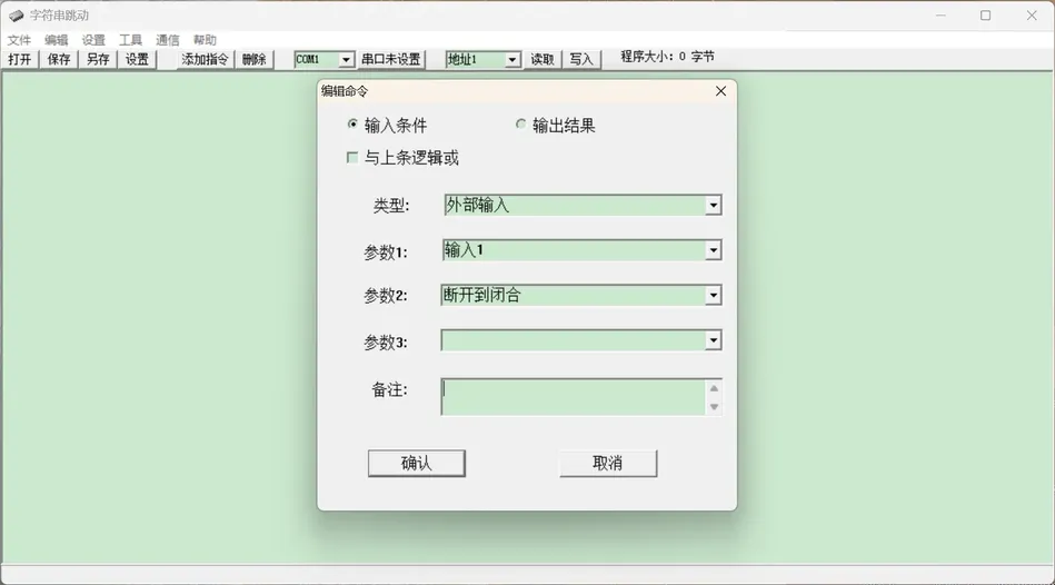
Select "Input Condition": Type=External Input, Parameter 1=Input 1, Parameter 2=Open/Close.
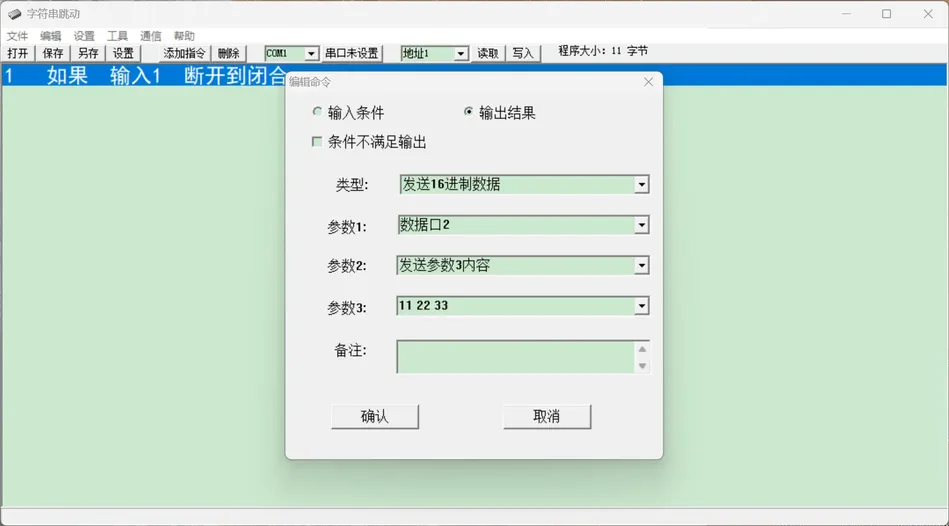
Select "Output Result": Type=Send hexadecimal data, Parameter 1=Data Port 2, Parameter 2=Send Parameter 3 content, Parameter 3=11 22 33.
Click "Confirm".
Add another instruction, select "Input 1, Close to Open" as the input condition, and fill in 22, 33, and 44 as the output parameter 3.
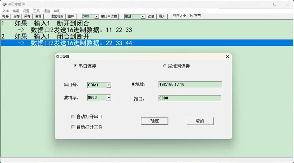
Click on the toolbar "Write" to download the rules to the module. (Default Address: 01 or 00)
7. Download and Read
| Button | Function |
| Read | Read the currently saved rules from the module to the software |
| Write | Compile the currently edited rules and send them to the module |
| Save/Save | Save the project as an. xk3 file |
| Open | Load the existing. xk3 project file |
After modifying the rules, you must click "Write" to take effect. Only saving the project file will not update the internal program of the module.
8. Debugging Techniques
- Use a serial port assistant or Modbus debugging tool to connect the module and observe whether the message sent when triggered is correct. If there is no response from the input, first check if the input channel number and trigger mode (level/edge) are selected correctly. If the received message is garbled or timed out, check whether the baud rate, data bits, stop bits, and checksum are consistent with the receiving end.
- If there is no response from the input, first check if the input channel number and trigger mode (level/edge) are selected correctly.
- If the received message is garbled or timed out, check whether the baud rate, data bits, stop bits, and checksum are consistent with the receiving end.
- The program size displays the number of bytes compiled by the current rule, but be careful not to exceed the module storage capacity. When multiple rules exist simultaneously, pay attention to the combination logic of "OR with the previous logic" to avoid conflicting conditions.
- When multiple rules coexist, pay attention to the combination logic of "or" with the previous logic to avoid conflicting conditions.
9. Precautions
- Before configuring, confirm that the communication between the PC and the module is normal, and that the serial or network port parameters match.
- Do not connect RS485 bus A and B lines in reverse, and pay attention to terminal resistance when multiple modules are connected in parallel. When it comes to relay output, the load current and voltage should not exceed the rated value of the module. After the modification is completed, save the project file in a timely manner and write it into the module.
- When it comes to relay output, the load current and voltage should not exceed the rated value of the module.
- After the modification is completed, save the project file in a timely manner and write it into the module.
- Please refer to the manufacturer's documentation for specific function codes, register addresses, and communication protocol details.
10. Quick Reference
Common trigger method selection
- Detection button press: open to close
- Detection button release: close to open
- Detection switch status: closed/open
- Detection of any change: state flip


Leave a Reply