
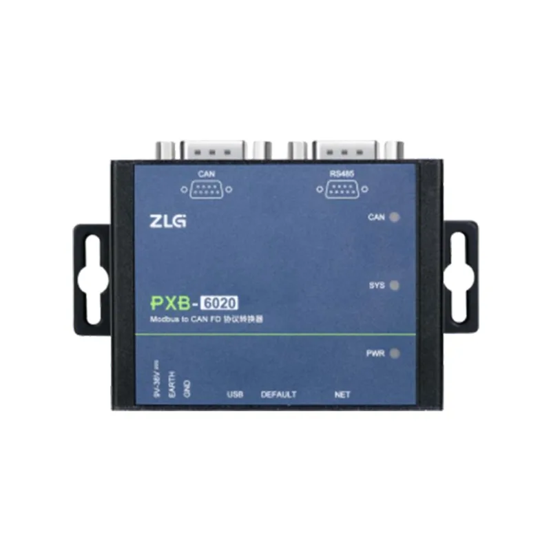
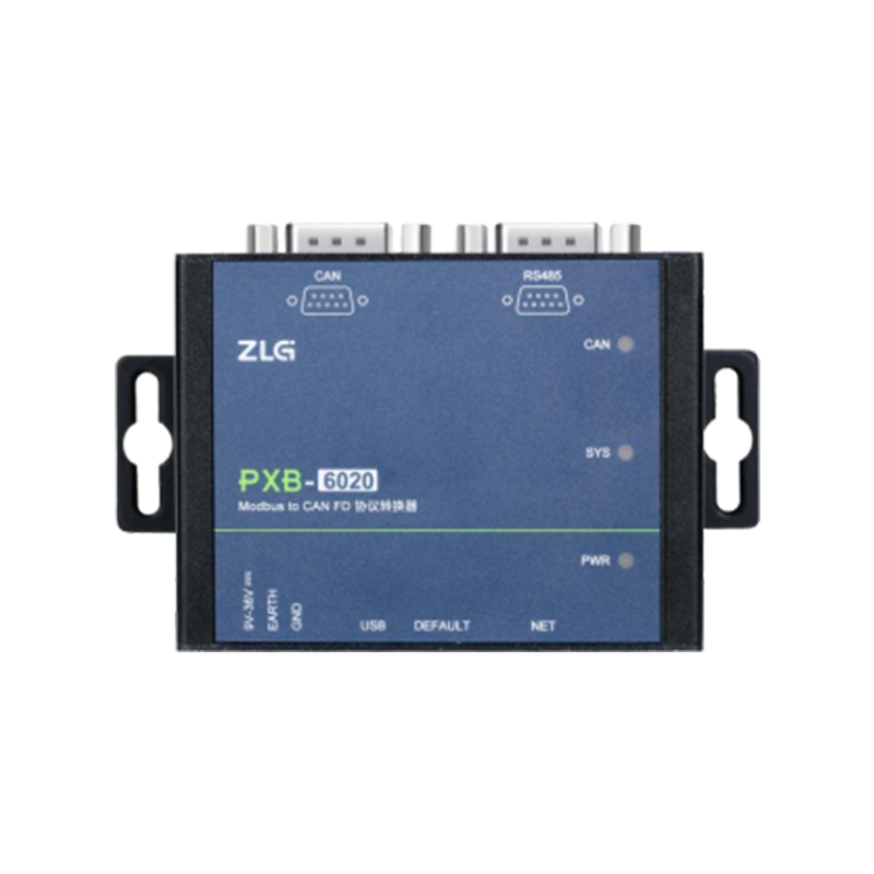
 Product IntroductionPXB-6020 is a Modbus and CAN FD protocol converter. The device can realize data interoperability between Modbus protocol and CAN FD bus.
Among them, Modbus supports two protocol types: RTU and TCP, and the device supports two modes: Master and Slave, which greatly facilitates connection with other control devices with different protocols.
The PXB-6020 supports 128 groups of periodic sending messages and 128 groups of white list receiving messages, with high accuracy of periodic sending messages. At the same time, the device supports a custom send mode. By using the custom send mode method, CAN FD data frames can be flexibly sent on demand.
The PXB-6020 is an industrial-grade protocol conversion device with a working temperature range of-40 ° C to +85 ° C and supports a wide voltage power input of 9V to 36V. The CAN FD interface and RS485 interface are electrically isolated and can be used in various industrial control occasions.Product CharacteristicsThe characteristics of PXB-6020 product are as follows:
Hardware characteristics:
32-bit high-performance RISC-V core, 816MHz CPU frequency;
The conversion time is about 1ms, and the conversion is fast;
The communication interface is fully isolated, stable and reliable;
The equipment has passed multiple rigorous tests such as EMC and environmental tests, achieving true industrial-grade quality;
Adaptive 10/100M Ethernet interface (RJ45 interface);
Exquisite and compact, easy to install;
Wide voltage input: DC 9~36V, typical working current 100mA;
Working temperature: -40 ° C ~ +85 ° C;
Storage temperature: -40 ° C ~ +85 ° C;
Functional characteristics:
Serial port baud rate supports user settings of 9600 to 2000000bps, and supports up to 2M ultra-high baud rate;
Serial data bit, stop bit, and check bit can be set;
IP address, slave ID, target IP and port can be set;
Provide four working modes: Modbus RTU master/slave, Modbus TCP master/slave;
Support sending and receiving CAN, CAN FD and CAN FD acceleration messages;
CAN FD rate supports up to 5M ultra-high baud rate;
Support standard frames, extended frames and remote frames;
Support 128 groups of periodic sending messages and 128 groups of whitelist receiving messages;
Support setting of parameters such as CAN type, CAN FD standard and CAN FD acceleration;
Support custom sending mode, and you can customize and accurately send CAN or CAN FD messages;
Support setting periodic sending waiting time;
Equipped with AWPX Tools configuration software, it is easy to use and quick to get started;
Support one-click restoration of factory settings with multiple guarantees;
Support one-click remote firmware upgrade.
Product IntroductionPXB-6020 is a Modbus and CAN FD protocol converter. The device can realize data interoperability between Modbus protocol and CAN FD bus.
Among them, Modbus supports two protocol types: RTU and TCP, and the device supports two modes: Master and Slave, which greatly facilitates connection with other control devices with different protocols.
The PXB-6020 supports 128 groups of periodic sending messages and 128 groups of white list receiving messages, with high accuracy of periodic sending messages. At the same time, the device supports a custom send mode. By using the custom send mode method, CAN FD data frames can be flexibly sent on demand.
The PXB-6020 is an industrial-grade protocol conversion device with a working temperature range of-40 ° C to +85 ° C and supports a wide voltage power input of 9V to 36V. The CAN FD interface and RS485 interface are electrically isolated and can be used in various industrial control occasions.Product CharacteristicsThe characteristics of PXB-6020 product are as follows:
Hardware characteristics:
32-bit high-performance RISC-V core, 816MHz CPU frequency;
The conversion time is about 1ms, and the conversion is fast;
The communication interface is fully isolated, stable and reliable;
The equipment has passed multiple rigorous tests such as EMC and environmental tests, achieving true industrial-grade quality;
Adaptive 10/100M Ethernet interface (RJ45 interface);
Exquisite and compact, easy to install;
Wide voltage input: DC 9~36V, typical working current 100mA;
Working temperature: -40 ° C ~ +85 ° C;
Storage temperature: -40 ° C ~ +85 ° C;
Functional characteristics:
Serial port baud rate supports user settings of 9600 to 2000000bps, and supports up to 2M ultra-high baud rate;
Serial data bit, stop bit, and check bit can be set;
IP address, slave ID, target IP and port can be set;
Provide four working modes: Modbus RTU master/slave, Modbus TCP master/slave;
Support sending and receiving CAN, CAN FD and CAN FD acceleration messages;
CAN FD rate supports up to 5M ultra-high baud rate;
Support standard frames, extended frames and remote frames;
Support 128 groups of periodic sending messages and 128 groups of whitelist receiving messages;
Support setting of parameters such as CAN type, CAN FD standard and CAN FD acceleration;
Support custom sending mode, and you can customize and accurately send CAN or CAN FD messages;
Support setting periodic sending waiting time;
Equipped with AWPX Tools configuration software, it is easy to use and quick to get started;
Support one-click restoration of factory settings with multiple guarantees;
Support one-click remote firmware upgrade.4. Device configuration
PXB series protocol converters are configured through AWPX Tools software (hereinafter referred to as AWPX).。
After the product is powered on, the PXB-6020 product and the PC host running AWPX software can be connected to the same local area network through Ethernet cable (through switch or direct connection) for configuration.
4.1 Configure software installation
Double-click the installation package of AWPX to start installing AWPX. After double-click, the installation start interface is as shown in Figure 4.1.
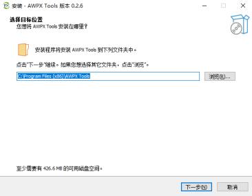
Figure 4.1 Starting the installation of AWPX
After clicking several [Next], the installation interface is as shown in Figure 4.2.
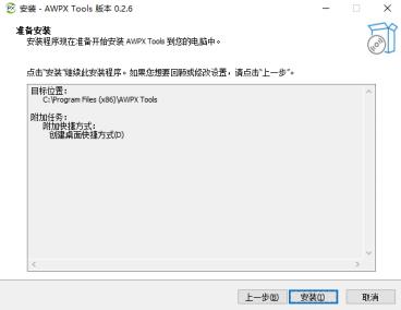
Figure 4.2 AWPX installation interface
Finally, click [Install] to officially start the installation of AWPX and wait patiently for the installation to complete.
4.2 Introduction to Configuration Software Interface
Run AWPX software, and the interface is shown in Figure 4.3.
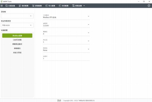
Figure 4.3 AWPX Interface
On the left side of the AWPX interface is the device information of the PXB series products, including "Target Board","Protocol Conversion Type" and "Device Configuration". On the right side of the "Device Configuration" column is specific information about configuration options.
At the top of the interface are menu bar buttons, including buttons such as [Scan Device],[Save Configuration], and [Get Configuration]. As shown in Figure 4.4.

Figure 4.4 Menu bar button
1 , Scanning Device
Click the [Scan Device] button, and the AWPX software will search for all PXB-60 series devices in the current local area network, and display the IP address and firmware version of the target board in the "Target Board" drop-down box. After selecting the correct device in the "Target Board" drop-down box, you can configure the PXB-6020.
2 . Save Configuration
After modifying any parameters, click the [Save Configuration] button to send the modified configuration to PXB-6020, so that the modified configuration takes effect. Saving the configuration will restart the PXB-6020 and wait for the restart prompt that appears at the bottom of the software to disappear.
3 . Get configuration
After selecting the device, click the [Get Configuration] button to obtain and display the current running configuration of PXB-6020.
4 , Import Configuration
After selecting the device, click the [Import Configuration] button to import the configuration file with the suffix.awp into the AWPX software. After importing the correct configuration, you can modify the imported configuration or save it directly to PXB-6020.
5 . Export Configuration
After selecting the device, click the [Export Configuration] button to export the currently configured parameters to a configuration file with the suffix.awp. So that the next time you use AWPX, you can quickly import and configure the configuration file saved locally through the [Import Configuration] button.
6 , System Settings
The [System Settings] button includes three sub-options:[Network Settings],[Firmware Upgrade] and [About].
[Network Configuration]: Used to set network parameters such as the IP address, subnet mask and default gateway of the PXB-6020. See section "4.3.1" for the specific interface.
[Firmware Upgrade]: Used to upgrade and update firmware for PXB-6020. See Section "4.3.7" for the specific interface. [About]: Version information related to AWPX software.
4.3 Use configuration software to configure
The main steps to configure PXB-6020 using AWPX configuration software are:
The first step is to click [Scan Device] and select the correct device. If the device is not scanned and selected, no configuration will be possible for the PXB-6020.
The second step is to configure parameters. You can configure the parameters in the "Device Configuration" column and network parameters according to your needs.
Step 3: After the parameter configuration is completed, click [Save Configuration] to save the configured parameters to PXB-6020.
4.3.1 Network Settings
The default IP address of PXB-6020 is "192.168.1.136", if you need to change network parameters such as IP address, you can click the [System Settings] button at the top of the software interface, and click the [Network Settings] button in the pop-up menu to make network settings, as shown in Figure 4.5.
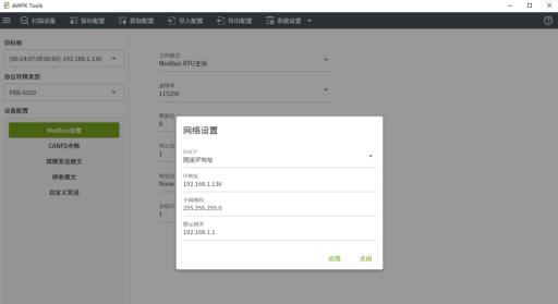
Figure 4.5 Network Settings
4.3.2 ModbusParameter Configuration
Click [Modbus Settings] in the "Device Configuration" column of AWPX software to configure Modbus parameters, including RTU communication parameters such as working mode, baud rate, and check bit. The serial port baud rate can be configured to up to 2M. The configuration interface is shown in Figure 4.6.

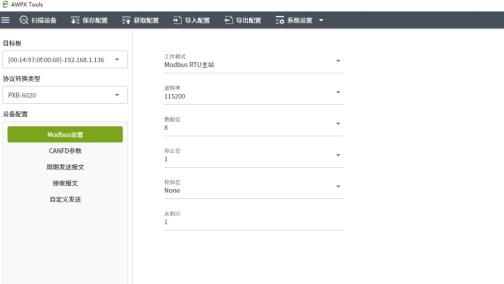
Figure 4.6 Modbus Parameter Settings
PXB-6020 supports four working modes, which can be selected through the "Working Mode" drop-down list box. Each working modehas corresponding Modbus parameters. The functional descriptions and corresponding parameter descriptions of these four working modes are shown in Table 4.1.
Table 4.1 Modbus Parameter Description
|
Working Mode |
Function Description |
Configuration Item |
Configuration Item Description |
|
Modbus RTU Master Station |
PXB-6020 works in Modbus RTU Master Mode, and can be externally connected to the USB Modbus slave |
baud rate |
RTU communication parameters |
|
Data bit |
|||
|
Stop bit |
|||
|
Check bit |
|||
|
Slave ID |
External unique slave ID |
||
|
Modbus RTU slave station |
PXB-6020 works in Modbus RTU slave mode. External Modbus master can read and write PXB- 6020 register |
baud rate |
RTU communication parameters |
|
data bits |
|||
|
Stop bit |
|||
|
Check bit |
|||
|
Native slave ID |
PXB-6020 as ID of slave |
||
|
Modbus TCP master |
PXB-6020 works in Modbus TCP master mode |
Slave IP address |
IP address of unique TCP slave |
|
Slave port number |
Port number of unique TCP slave |
||
|
Peer slave number |
Unique TCP slave ID |
||
|
Modbus TCP slave |
PXB-6020 Working in Modbus TCP slave mode, an external Modbus host can read and write PXB- 6020 register |
local port number |
PXB-6020 as the port number of the slave |
|
local slave number |
PXB-6020 as the ID of the slave |
4.3.3 CAN FDParameter Configuration
PXB-6020 can send CAN or CAN FD messages when working in either working mode. At AWPX
Click [CAN FD Parameters] in the "Device Configuration" column of the software to configure CAN FD parameters. The interface is shown in Figure 4.7.
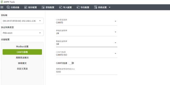
Figure 4.7
CAN FD parameter descriptions are shown in Table 4.2.
Table 4.2
CAN FD Parameter Interface
CAN FD Parameter Description
|
Parameter |
Parameter Description |
|
CAN type selection |
Type selection can be selected for CAN or CAN FD |
|
Arbitration segment baud rate |
Set the arbitration segment baud rate of CAN or CAN FD messages |
|
Data segment baud rate |
Type is valid for CAN FD. Set the baud rate of the data segment of the CAN FD message |
|
CAN FD standard |
Type is valid for CAN FD, set the standard used in the CAN FD message |
|
CAN FD acceleration |
type is valid for CAN FD, Used to set whether CAN FD acceleration is enabled for the sent CAN FD messages |
|
Periodic transmission waiting time |
Used to set how long to wait after the completion of power-on initialization of the PXB-6020 before starting periodic transmission of messages |
4.3.4 Periodic transmission of messages configuration
The PXB-6020 can periodically send CAN or CAN FD messages when working in any working mode. Whether a message sent periodically depends on the setting of [CAN Type Selection] on the [CAN FD Parameters] interface whether it is a CAN frame or a CAN FD frame.
Click [Periodic Send Message] in the "Device Configuration" column of the AWPX software to check the parameters of periodic send messages
. The periodic send message interface is shown in Figure 4.8.
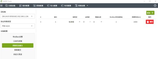
Figure 4.8 Periodic Sending Message Interface
Use the [Add +] button in the upper right corner of the interface to add messages sent periodically. Add a maximum of 128 messages sent periodically. If you need to delete messages sent periodically, you can delete them by using the [Delete] button on the right side of the interface.message sending interface are shown in Table 4.3.
Table 4.3 Parameter description of periodic sending message interface
|
Parameter description |
Parameter description |
|
Frame ID |
Set the frame ID to be sent periodically, which can be decimal or hexadecimal (need to start with 0x) |
|
Frame type |
is set to standard frame or extended frame |
|
Remote frame |
Whether the transmitted frame is a remote frame, when CAN type is selected as CAN FD, this option is invalid |
|
Data length |
Transmission frame data segment length, maximum 8 bytes for CAN frames, Up to 64 bytes when CAN FD frames |
|
Modbus register address |
Message data sent cyclically is stored at the starting address of the device or Modbus slave's retention register |
|
Cycle Time |
Sets the time interval for cyclically sending messages, in ms |
The data source of cyclically sending messages is in the holding register of the Modbus slave.
If the PXB-6020 is running in Modbus master mode, the data source of the cyclically transmitted message is in the retention register of the external Modbus slave. If the PXB-6020 is running in Modbus slave mode, the data source of the periodically transmitted message is in the internal retention register of the PXB-6020.
If the cycle is set to transmit CAN FD frames with a length of 8, and the Modbus register address is set to 1, the data storage rules are as follows:
Assume that the data in the Modbus slave's retention register is: 1 Address: 0x1234, 2 Address: 0x5678.
Then PXB-6020 will read data starting from address 1 and periodically send CAN FD frames: 34 12 78 56 00 00 00 (hexadecimal). The number of read hold registers depends on the length of the message sent in the set cycle.
4.3.5 Receive Message Configuration
The PXB-6020 works in any working mode and can receive CAN or CAN FD messages. Whether the received message is a CAN frame or a CAN FD frame depends on the setting of [CAN Type Selection] on the [CAN FD Parameters] interface.
Click the [Receive Message] button in the "Device Configuration" column of the AWPX software to configure the parameters of the received message
parameters for receiving messages. The interface is shown in Figure 4.9.
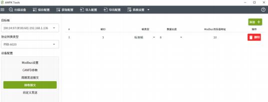
Figure 4.9 Received Message Interface
Use the [Add +] button in the upper right corner of the interface to add the messages you need to receive. Add a maximum of 128 received messages. If you need to delete the received message, you can use the [Delete] button on the right side of the interface to delete it. The parameter descriptions of the message receiving interface are shown in Table 4.4.
Table 4.4 Parameter Description of Received Message Interface
|
Parameter |
Parameter Description |
|
Frame ID |
Sets the frame ID of the received message, which can be decimal or hexadecimal (Must start with 0x) |
|
Frame type |
Sets whether the received message is a standard frame or an extended frame |
|
Data length |
When receiving a CAN frame, the maximum is 8 bytes. Up to 64 bytes when receiving a CAN FD frame |
|
Modbus register address |
Received message data is stored to the starting address of the local or Modbus slave retention register |
The PXB-6020 will write the received message data into the holding register of the Modbus slave.
If the PXB-6020 is running in Modbus master mode, the received message data will be written into the retention register of the external Modbus slave. If the PXB-6020 is running in Modbus slave mode, the received message data will be written into the retention register internal to the PXB-6020.
If you set a CAN FD frame with a length of 8 and set the Modbus register address to 1, the data storage rules are as follows:
Suppose the received CAN FD frame is: 12 34 56 78 00 00 00 (hexadecimal).
Then PXB-6020 will write data 0x3412 in the hold register of Modbus slave address 1, and write data 0x7856 in the hold register of address 2. Data 0x0000 is written to the hold register at addresses 3 to 4. The number of written retention registers depends on the set length of the received message.
4.3.6 Custom Send Configuration
Click [Custom Send] in the "Device Configuration" column of AWPX software to customize the parameter configuration of sending messages, and you can customize sending CAN or CAN FD messages. Whether you send a CAN frame or a CAN FD frame depends on
Depending on the settings of [CAN Type Selection] on the [CAN FD Parameters] interface. The customized sending interface is shown in Figure 4.10.
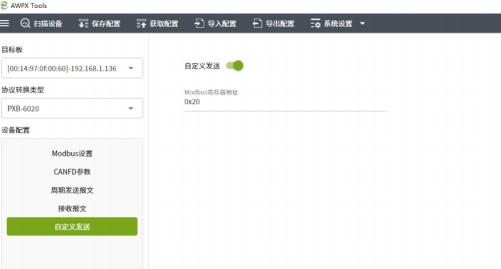
Figure 4.10 Custom Send Interface
Among them, the [Modbus Register Address] option is used to configure the data source of the customized message sent. The data source of the customized message sent is in the holding register of the Modbus slave.
If the PXB-6020 is running in Modbus master mode, the data source of the customized sent message is in the retention register of the external
Modbus slave. If the PXB-6020 is running in Modbus slave mode, the data source for the customized sent message is in the internal retention register of the PXB-6020.
Click the [Custom Send] button to enable custom sending, and then fill in the data format shown in Table 4.5 in the retention register of the corresponding address of the Modbus slave to customize the data and format of the sent message.
Table 4.5 CAN/CAN FD Data Area Format
|
Field |
Register Number |
subkey |
describes that the value of the |
|
transaction sequence number |
1 |
/ |
is greater than 0, which means that the following data areas are valid, and this sequence number needs to be incremented every time an update is sent. When the value reaches 65535, the lower 8 bits of the 1 |
|
CANID |
2 |
/ |
0 - 28 valid |
|
frame information |
1 |
flag |
can be returned, which is defined as follows: B2: Remote frame bits B3: Extended frame bits Other bits reserved |
|
Data length |
Upper 8 bits |
||
|
CAN/CAN FD data |
32 or 4 |
/ |
Length 4 when operating in CAN mode, otherwise 32 |
Example of custom sending: If [CAN Type Selection] is set to CAN in AWPX software, and custom sending is enabled, the [Modbus Register Address] for custom sending is set to 30.
Then the holding registers with addresses 30 to 37 in the Modbus slave are filled in 0x0001, 0x0000, 0x0123, 0x0800, 0x1122, 0x3344, 0x5566, 0x7788. When the value of the register with address 30 is incremented every time, PXB- 6020 will issue a frame ID with 0x0123. The data is a CAN standard frame of 22 11 44 33 66 55 88 77 (hexadecimal).
4.3.7 Firmware Upgrade
Click [System Settings], click [Firmware Upgrade] in the pop-up menu, and AWPX will pop up the upgrade interface, as shown in Figure 4.11.
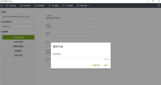
Figure 4.11 Firmware Upgrade
Click [Select Firmware] in the selection box to select the firmware (bin file) to be upgraded. Click [Firmware Upgrade], AWPX will prompt you that firmware is being downloaded to the device. The entire upgrade process lasts about 2 minutes.
In about 1 minute, AWPX will prompt the device that the firmware download was successful and the PXB-6020 will automatically restart. Just wait patiently for about 1 minute. During this restart process, do not disconnect the power supply to the PXB-6020. After the firmware upgrade is completed, you need to click the [Scan Device] button again to scan again and select the device for configuration.
5. Typical application
The PXB-6020 can easily realize PLC expansion of CAN/CAN FD bus capabilities and empower lithium battery, photovoltaic, and automotive parts production line testing. A typical application of PXB-6020 is shown in Figure 5.1.
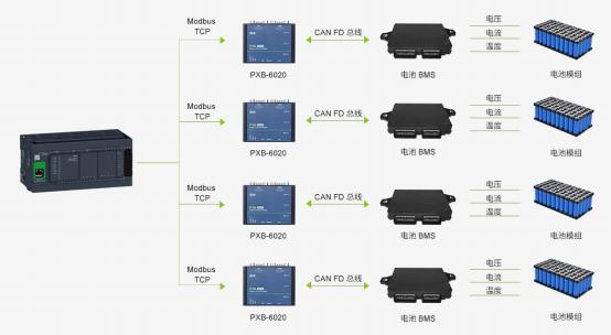
Figure 5.1 Typical application of PXB-6020


这个多少钱