
1 Basic Modbus Parameter Description
Application of the Modbus Protocol. This section mainly explains from the following parts:
- Enabling the Protocol
- Configuring Master and Slave Devices
- Creating Variables
- Relationship between Variable Addresses and Values
- Logical Processing
1.1 Enabling the Protocol
The configuration interface for the Modbus protocol is located in the menu bar of the VisualTFT host computer, under "Tools" → "Protocol and Variable Settings…". Click the file path on the left, and in the protocol settings column on the right, set the protocol type. If you select Modbus Master, enable the protocol as shown below
. After enabling the Modbus protocol, the control can display "Associated Variables" on the configuration interface.

1.2 Configuring Master and Slave Devices
Master Mode
Configuration and parameters of the Modbus master are as follows:
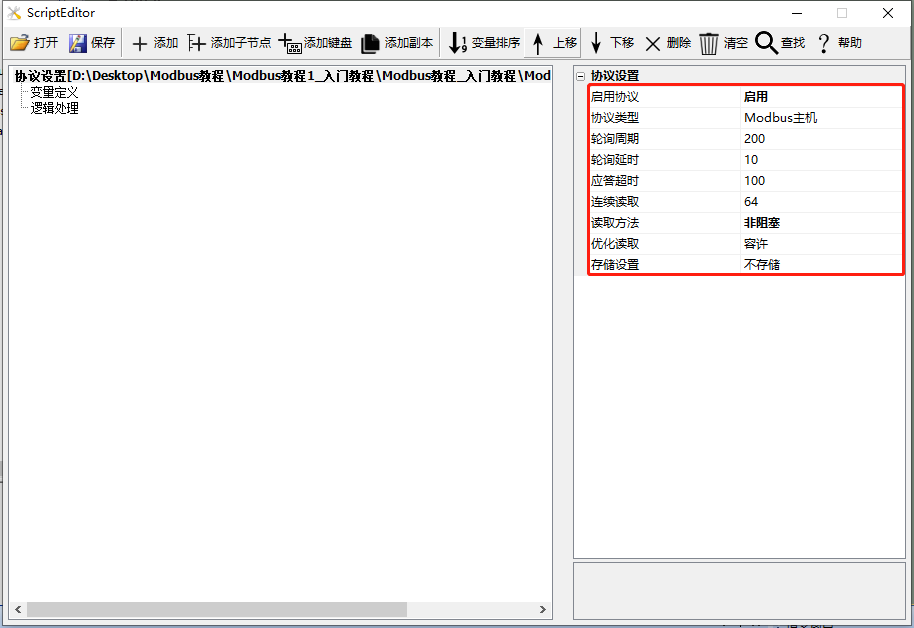
- Enable protocol: The protocol needs to be enabled to support the Modbus protocol.
- Protocol type: Select Modbus master.
- Polling cycle: This parameter is invalid and does not need to be set.
- Polling delay: When the screen acts as the master, the time to wait for sending the next request command after sending a request command and receiving a response from the screen.
- Response timeout: When the screen acts as the master, the maximum delay allowed for the slave is 100 milliseconds by default.
- Continuous reading: Set the maximum number of continuous address variables to read.
- Optimized reading: After enabling optimized reading, only variables related to the current screen are read.
- Storage settings: After enabling storage, Flash addresses 0~2048, approximately 2K, are used to store all Modbus variables. Other storage should avoid this address! Do not store: Do not store. After power-off and restart, variables will return to their default values. Store all: Not recommended, as frequent storage can lead to an increase in bad blocks in FLASH. Specify variables to store: Recommended for storing system configuration parameters that rarely change.
- Storage tag: Identify the data version tag stored in the screen. When the storage data format changes, the storage tag value generally needs to be manually modified.
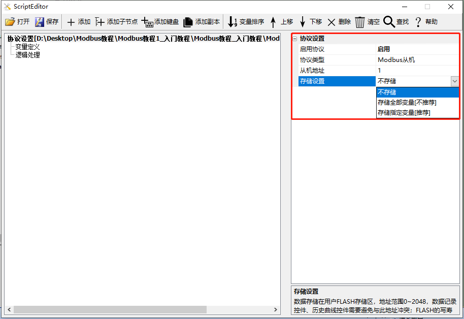
Slave mode
- Enable protocol: The protocol needs to be enabled to support the Modbus protocol
- Protocol type: Select Modbus slave
- Slave address: Default is 1
- Storage setting: After enabling storage, Flash addresses 0~2048, approximately 2K, are reserved for Modbus variable storage. Other storage should avoid these addresses! Do not store: Do not store. After power-off and restart, variables will return to their default values. Store all: Not recommended, as frequent storage can lead to an increase in FLASH bad blocks. Specify variable storage: Recommended for storing system configuration parameters that rarely change
- Storage flag: Identify the data version flag stored on the screen. When the storage data format changes, the storage flag value generally needs to be manually modified
1.3 Variable definition
Click "Variable definition", then click "Add" to add a variable, as shown below
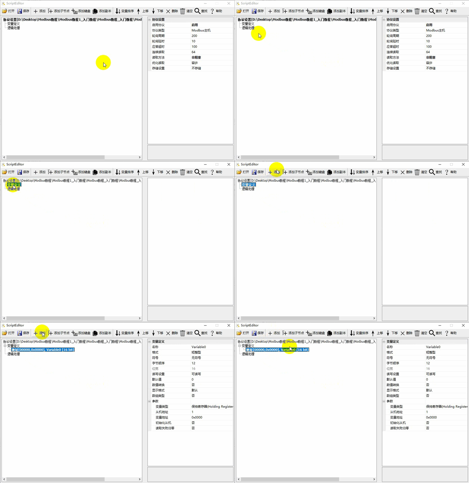
Variable definition
Detailed variable analysis is as follows
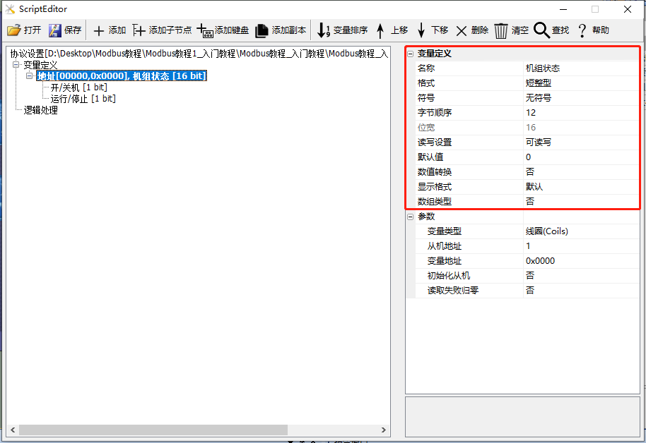
- Name: The default variable names are "Variable1, Variable2, Variable3...", which can be defined with meaningful names such as: unit status; if the variable needs to be bitwise interpreted, the default names are "Field1, Field2, Field3...", which can be defined with meaningful names such as: on/off, running/stopped
- Format: Supports short integer, long integer, single-precision floating-point number, and string
- Symbol: Can be set to unsigned or signed
- Read-write setting: Set the read-write permissions for the variable, supporting read-write, read-only, and write-only
- Default Value: The default display value
- Value Conversion: Convert the variable, for example: Actual Value = Original Value * Scale + Offset
- Display Format: Set the number of digits for integers and decimals
- Array Type: Enable the array type, starting from the address of this variable, and operate on consecutive N registers
- Storage: When configuring the Modbus master/slave protocol, enable the storage setting. If storage is selected here, the data can be saved during power loss
Parameters
Detailed parameter setting analysis is shown below
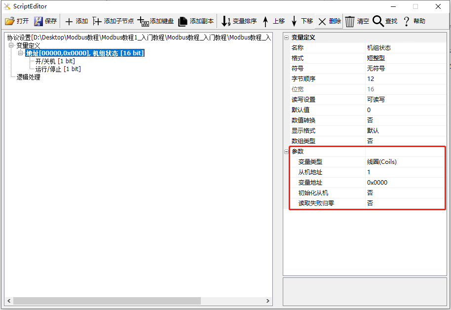
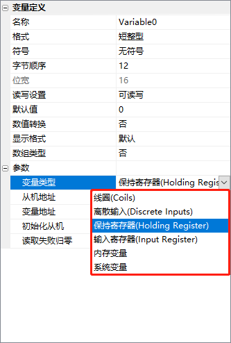
- Variable Type: Coil, Discrete Input, Holding Register, Input Register, Memory Variable, System Variable
- Slave Address: Only required when the screen acts as a master
- Variable Address: The address of the variable (or register), filled in hexadecimal
- Initialize Slave: When the screen acts as a master, after the screen is powered on, write the value of the variable to the slave device
- Read Failure Zeroing: When the screen acts as a master, if the variable fails to be read, the value of the variable is reset to zero
1.4 Relationship between Variable Address and Value
Coil/Discrete Data
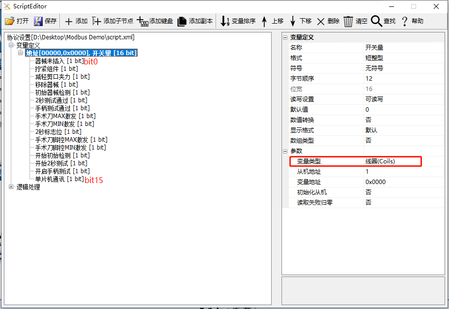
Create a coil or discrete input register with a variable format of short integer type, which contains 16 coils (from top to bottom, bit0...bit15). Assuming the variable address is 0x0000, the variable includes addresses ranging from 0x0000 to 0x000F. Each bit corresponds to one coil, as shown below
String Type
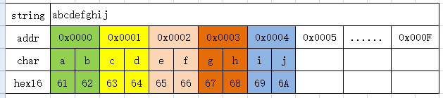
Create a save register with a variable format of string type (default 32 characters). Assuming the variable address is 0x0000, this string corresponds to variables within the address range of 0x0000 to 0x000F, with each address corresponding to two characters
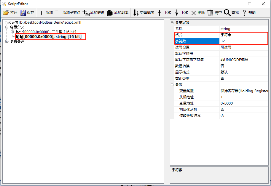
Assuming the save register address is 0 and the value is 'abcdefghij', as shown below
Array
Create an input register of array type (default array size is 10, with subscripts starting from 0). Assuming the variable address is 0x0000, this variable represents 10 consecutive variables starting from 0x0000, with each array subscript corresponding to one variable
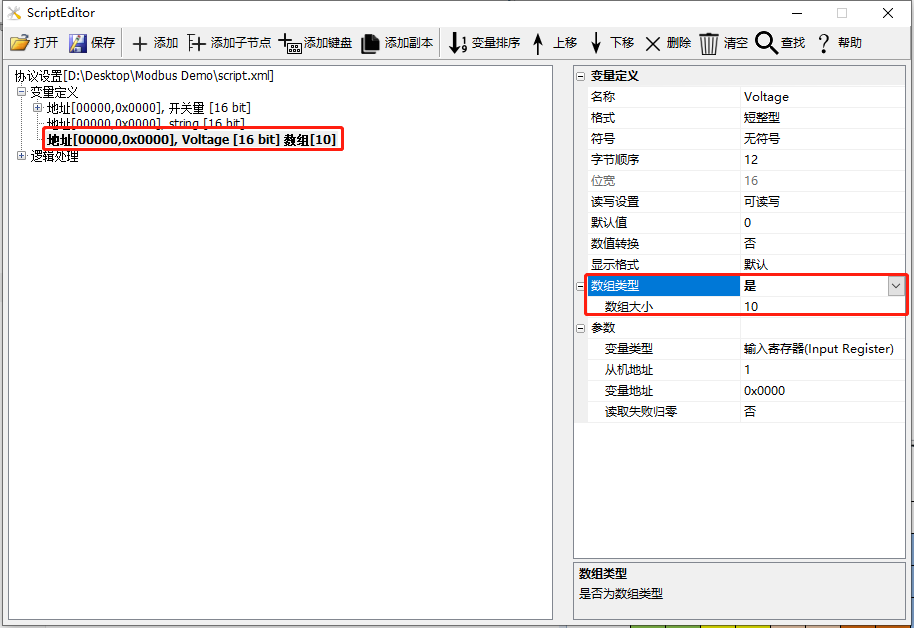
Assuming a variable named Voltage is created as an input register of array type with a size of 10, the correspondence is as follows

1.5 Logic Processing
Select the "Logic Processing" node on the left and click the "Add" button in the toolbar to add logic processing. As shown below, select the newly created logical relationship and set it through the property window
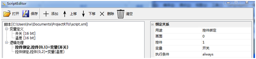
Introduction to General Property Parameters:
- Purpose: Set the purpose of the current logic, such as control binding, control display, etc.
- Screen: The screen ID where the control is located
- Control: Control ID
- Variable: Name of the variable associated with the control
- Execution Condition: You can set the execution condition of this logic. 'Always' indicates that it is always executed, while 'Changed' indicates that it is executed when the variable changes
1.5.1 Control Binding
Set the variable associated with the control: When the control changes, the variable value is automatically updated; conversely, when the variable updates, the control display is updated
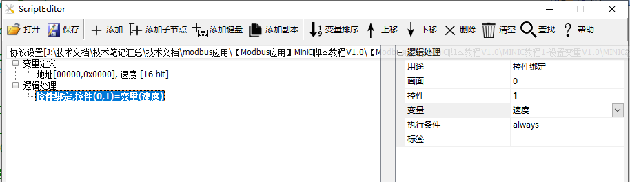
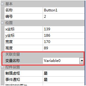
Using VisualTFT software version V3.0.0.765 and above, you can also directly set the associated variable name in the configuration control property window, as shown below, with a button control bound to a variable
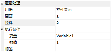
1.5.2 Control Display
Display the control when the set 'Execution Condition' is met, otherwise hide the control
1.5.3 Animation Playback
Start playing the animation when the set 'Execution Condition' is met, otherwise stop playing
1.5.4 Button Press and Release
When a button is pressed or released, if the "Execution Condition" is met, the "Execution Action" is executed
1.5.5 Condition Execution
When the "Execution Condition" is met, the "Execution Action" is executed. To prevent repeated execution, this logic is executed only once at the moment the condition is met (similar to rising edge triggering)
Screen Condition: This logic is limited to be effective only under a specific screen
1.5.6 Switch Screen
When the "Execution Condition" is met, switch to the specified target screen. This logic is triggered
- Target Parameter: The target screen can be a variable or a constant
- Screen Condition: This logic is limited to be effective only under a specific screen
1.5.7 Set Variable
When the "Execution Condition" is met, set the variable to a specified value
- Write Optimization: When optimization is enabled, writing is only executed when the target variable is changed
- Screen Condition: This logic is only valid under a specific screen
1.5.8 Assembly Instructions
Supported assembly instructions include: It is recommended to use Lua or MiniC scripting languages to implement complex interactions
- Jmp Jump: When the "Execution Condition" is met, jump to the "Target Label", only backward jumps are allowed
- Mov Assignment: MOV A B, set "Parameter Variable or Constant B" to "Target Variable B"
- Add Addition: ADD A B, result A = A+B
- Sub Subtraction: SUB A B, result A = A-B
- And Logical And: AND A B, result A = A&B
- Or Logical Or: OR A B, result A=A|B
- Mul Multiplication: MUL A B, result A=A*B
- Div Division: DIV A B, result A = A/B
1.5.9 Event Recording
When the "execution condition" is met, record the event ID
1.5.10 Curve binding
When the "execution condition" is met, record the specified variable in the "Historical Curve"
1.5.11 Color setting
When the "execution condition" is met, set the control to a specified color
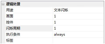
1.5.12 Text blinking
When the "execution condition" is met, set the text control to blink at a specified period
1.5.13 Buzzer control
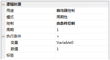
When the "execution condition" is met, control the buzzer to sound
- Mode: Can be set to "single" sounding or periodic sounding
- Control: For the periodic mode, can be set to start sounding, end sounding, or controlled by conditions
- Time: For the "single" mode, can be set to the sounding duration
- Cycle: For the "Cycle" mode, the sounding cycle can be set
1.5.14 External matrix keyboard
This feature is a customized function and is not supported in the regular version
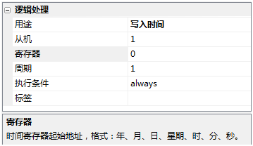
1.5.15 Write time
When the screen acts as the host, it can write to specified registers at a fixed time to set the slave time
2 How to create associated variables
The Modbus protocol of the large color serial port screen supports the creation of coils, discrete inputs, hold registers, input registers, content variables, and system variables, as shown below
| Variable type | Related description |
|---|---|
| Coils | Participate in communication: 0x01/0x05/0x0F |
| Discrete Input | Participate in communication: 0x02 |
| Holding Register | Participate in communication: 0x03/0x06/0x10 |
| Input Register | Participate in communication: 0x04 |
| Memory Variable | Not Participate in Communication: Used as intermediate variables, to record some information, etc. |
| System Variable | Not Participate in Communication: Such as system baud rate, running time, etc. |
The screen configuration in this chapter is set to host mode, introducing the creation and binding of coils, discrete inputs, holding registers, input registers, and system variables
Scope of Application: Full Series
Routine Download Link: <Modbus Tutorial 1_Beginner Tutorial V1.0"(Click to jump)
Protocol activation and variable related instructions, reference link:" Modbus Basic Parameter Description "
2.1 Coil
The [Coil] interface is used to display and control the state of the "Coil" variable in the MODBUS protocol. The button control is directly bound to the "Coil" type variable. The state of the coil is 0 or 1, corresponding to the button being up (0) or pressed (1). After running, when the "Coil" value at that address changes, the state of the button control changes in real time. Similarly, by clicking the button, the state of the coil variable type corresponding to the address in the slave device can be changed
Variable configuration
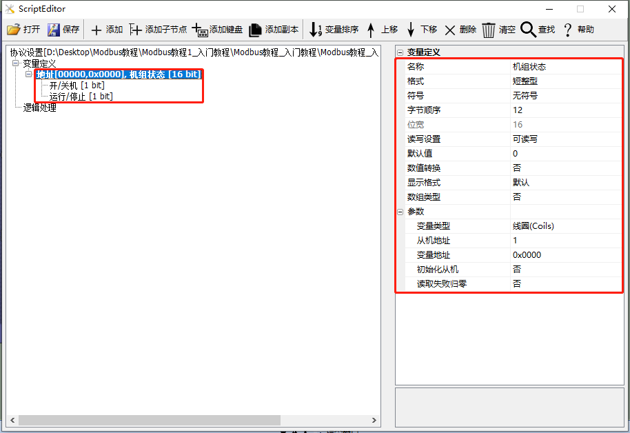
Add a "Unit Status" variable with the variable type set to "Coil", add child nodes "On/Off" and "Run/Stop", and configure the variable address to 0x0000. For detailed setting instructions, refer toModbus Basic Parameter Description, as shown below
Screen Configuration
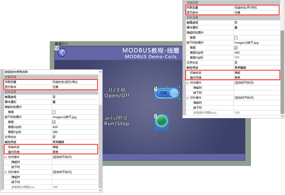
Screen Add a button control (control ID: 1), set the associated variable "Unit Status/On/Off" in the attribute bar of the button control, and the operation style of the button is switch, as shown below
Run Preview
Through the above two steps, the button control with control ID 1 has been associated with the variable "unit status/on/off". At this point, compile the project and run the virtual serial port screen to establish a connection with the MODBUS Slave software. The button control displays the status of "unit status/on/off". Simultaneously clicking the button control changes the state of the variable "unit status/on/off". Similarly, the button control with control ID 2, after being associated with the variable through the above method, implements corresponding status display and control functions. As shown below

2.2 Discrete Input
The [Discrete Input] screen displays the status of "discrete input" variables in the MODBUS protocol. The icon control is directly bound to variables of the "discrete input" type. The icon control will display the status of the variable, and when the value of the "discrete input" at that address changes, the icon control will correspondingly change
Variable Configuration
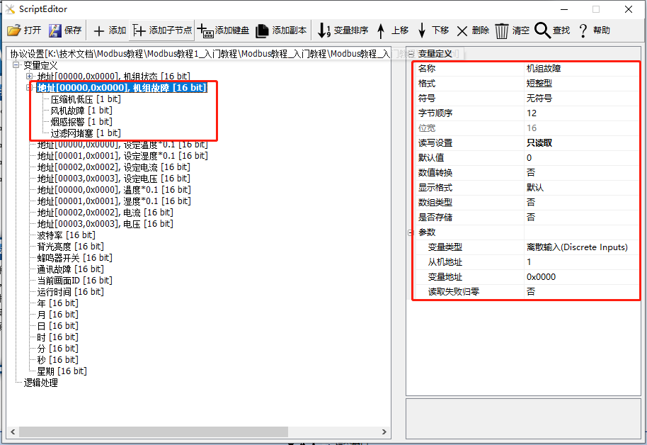
Add Variable: Create a "unit fault" variable, add a child node "compressor low pressure", set the variable type to "discrete input", configure the variable address to 0x0000, and refer toModbus Basic Parameter Descriptionfor detailed settings, as shown below
Screen Configuration
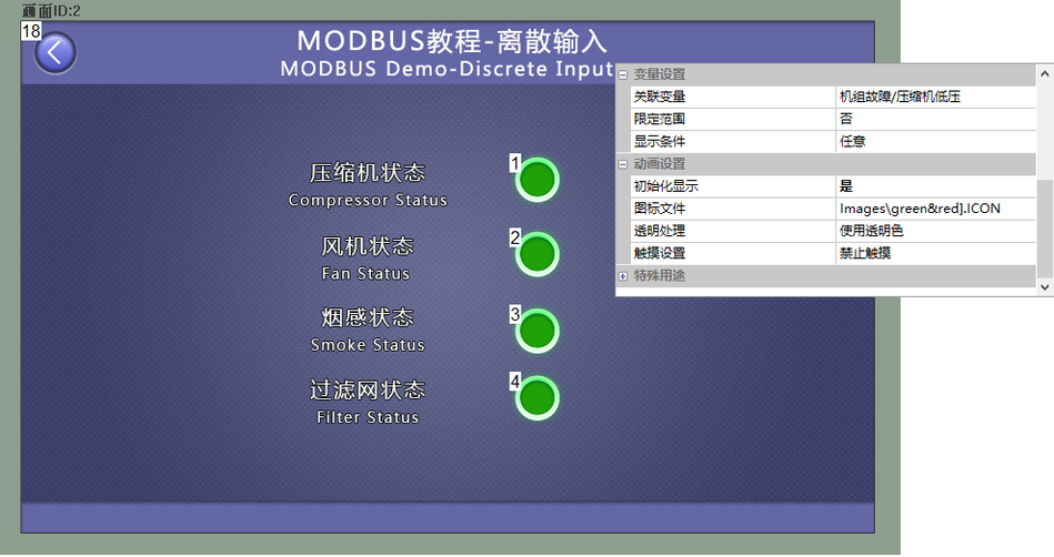
Add an icon control (control ID: 1) to the screen, and in the property column of the icon control, set the associated variable to "unit fault/compressor low pressure". Similarly, bind the icon controls with IDs 2~4 to their corresponding variables. Refer to"Configuration Control Tutorial - Icon Control"for instructions, as shown below
Run Preview
Through the above two steps, the icon control with control ID 1 has been associated with the variable "unit fault/compressor low pressure". At this point, compile the project and run the virtual screen serial port screen to establish a connection with the MODBUS Slave software. The icon control displays the status of the variable "unit fault/compressor low pressure". Similarly, by associating the icon controls with control IDs 2, 3, and 4 with different variables using the above method, the status of the corresponding address variables can be displayed, as shown below

2.3 Hold Register
The "Hold Register" screen directly displays the value of the "Hold Register" variable in the MODBUS protocol. The text control is directly bound to the "Hold Register" type variable. The text control will display the value of the variable, and when the value of the "Hold Register" at that address changes, the text control will correspondingly change
Variable Configuration
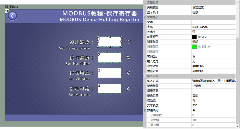
Add Variable: Create a "Set Temperature" variable, set the variable type to "Hold Register", and configure the variable address to 0x0000. If this variable represents temperature, and the transmitted value from the slave is 225℃, while the actual temperature is 22.50℃, then the scaling ratio between the actual value and the transmitted value is 0.1, and the offset value is 0. Therefore: Set "Value Conversion" to "Yes", "Scaling" to "0.1", and "Translation" to "0". For detailed settings, refer toModbus Basic Parameter Description, as shown below
Screen Configuration
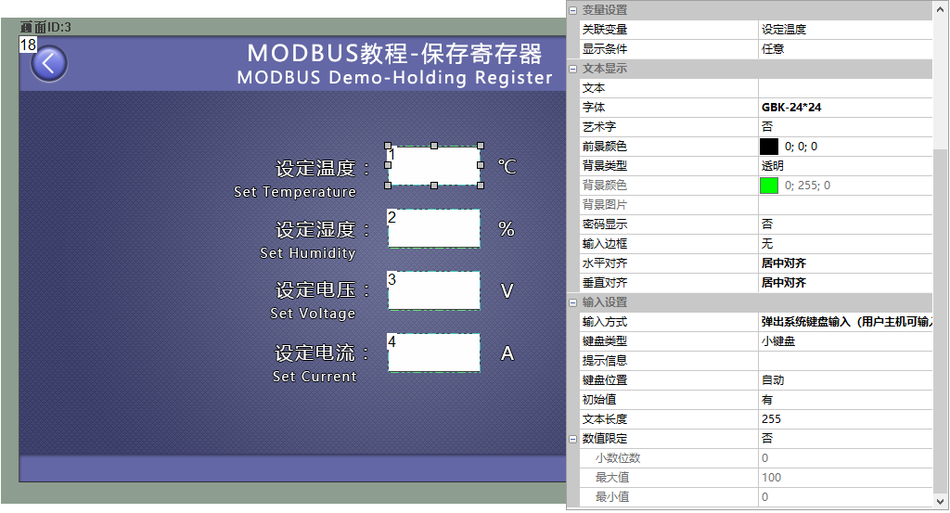
Add a text control (control ID: 1) to the screen, as shown in Figure 4-14. In the property bar of the text control, set the associated variable to "Set Temperature", and the input method to "Pop-up System Keyboard Input (user host can input)" mode, as shown below
Run Preview
Through the above two steps, the text control with control ID 1 has been associated with the variable "Set Temperature".

2.4 Input Registers
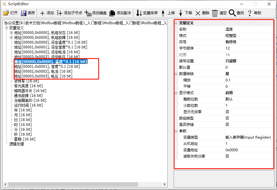
The [Input Register] screen directly displays the value of the "Input Register" variable in the MODBUS protocol. The text control is directly bound to a variable of type "Input Register", and the text control will display the value of the variable. When the value of the "Input Register" at that address changes, the text control will correspondingly change
Variable Configuration
Create a "Temperature" variable, set the variable type to "Input Register", and configure the variable address to 0x0000, as shown below.
Screen Configuration
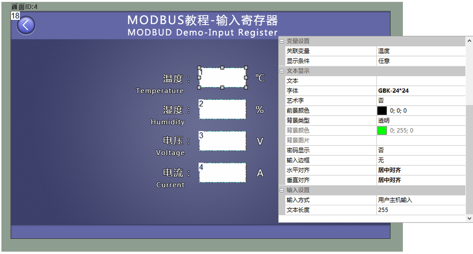
Add a text control (Control ID: 1) to the screen. In the property panel of the text control, set the associated variable to "Temperature", as shown below.
Run Preview
Through the above two steps, the text control with Control ID 1 is associated with the "Temperature" at address 0x0000. At this point, compile the project and run the virtual serial port screen, establish a connection with the MODBUS Slave software, and the text control will display the value of the hold register at address 0x0000. Similarly, by associating text controls with Control IDs 2, 3, and 4 with different variables through the above method, the corresponding address variable values can be displayed, as shown below.

2.5 System Variables
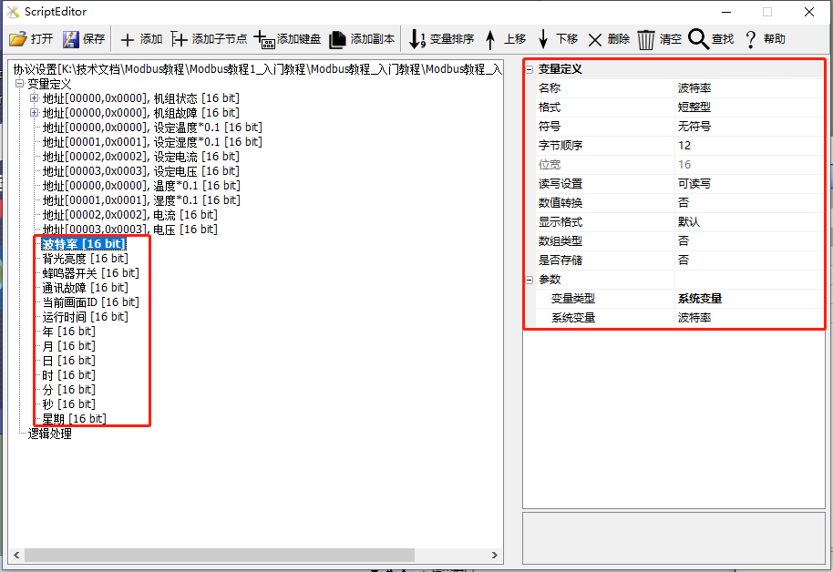
System variables are predefined variables in the system for direct access. The predefined variables on the screen include baud rate (readable), backlight brightness (readable and writable), buzzer switch (1 enables the buzzer, 0 disables it, readable and writable), communication fault (0 is normal, non-0 indicates a fault, readable), current screen ID (readable and writable), running time (unit: minutes, readable), date (readable), etc.
Variable Configuration
Add Variable: Create a "Backlight Brightness" variable, set the variable type to "System Variable", and the system variable parameter to "Backlight Brightness". Refer to the detailed setup instructionsBasic Modbus Parameter Description, as shown below
Screen Configuration
Add a Progress Bar Control (Control ID: 2) and a Slider Control (Control ID: 3) to the screen. In the property panel of the Progress Bar Control, set the sliding notification to "Associated Slider"; in the property panel of the Slider Control, set the associated variable to "Backlight Brightness". For specific applications of the Slider Control and Progress Bar Control, refer toTutorial on Configuration Controls - Slider Controlas shown below
Run Preview
Through the above two steps, the Slider Control with Control ID 2 is associated with the memory variable "Backlight Brightness"; at this point, compile the project and run the virtual serial port screen. Sliding the cursor of the "Slider Control" can control the screen's backlight brightness. Similarly, other Control IDs are bound to corresponding Text Controls or Button Controls, and after associating with different variables through the above method, the variable values of system variables can be displayed or controlled, as shown below

3 Button Controls and Text Controls
This chapter primarily introduces the common applications of button controls and text controls in the Modbus protocol. Simple controls can be bound to variables, which can be associated on the configuration page or bound to variables in [Tools - Protocols and Variables - Logic Processing]
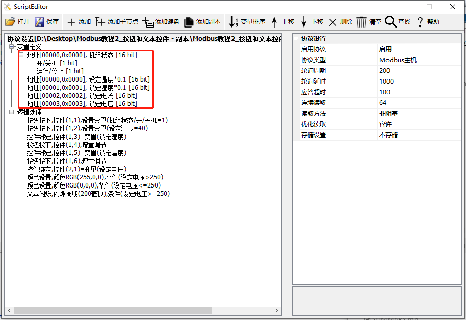
In this section, the screen acts as a master station, reading and writing slave instructions. If the screen acts as a slave station, the application of Text and Button Controls is the same, and reference can be made. This section creates 2 coils and 4 save registers to illustrate the application of Button Controls and Text Controls, as shown below
Scope of Application: Full Series
Routine download link: "Modbus Tutorial 1_Getting Started V1.0" (click to jump)
Protocol enablement, variable-related instructions, reference link:"Modbus Basic Parameter Description"
3.1 Button Control
On the [Button Control] screen, when the button is pressed or released in the MODBUS protocol version, some preset logical operations can be executed
Screen/logic configuration
Set shutdown
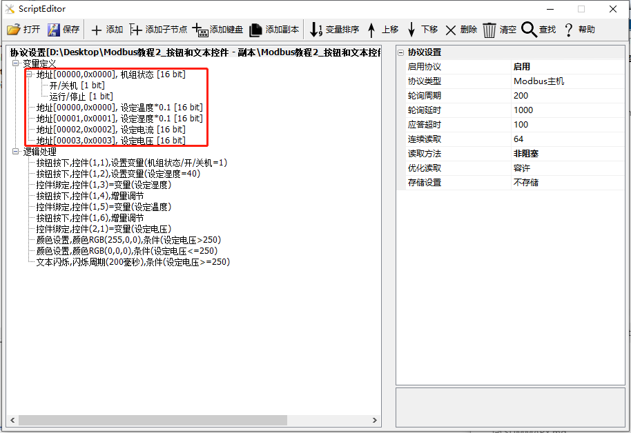
On the [Button Control] screen, for button control ID1, which is not directly associated with the control in the configuration interface, add the following logic processing
Add logic processing: For the purpose of [control binding], fill in the corresponding screen ID1 and button control ID1, with the variable being [unit status/on/off]
Set humidity to 40%
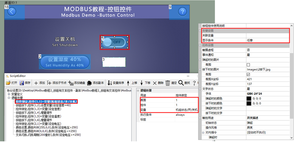
On the [Button Control] screen, there are a button control ID2 and a text control ID3. The configuration interface does not directly associate controls. Add the following logic processing
Article 1: Purpose: For [button press], fill in the corresponding screen ID1 and button control ID2. The execution action is [set variable], setting [set humidity] to 40
Article 2: Purpose: For [control binding], fill in the corresponding screen ID1 and text control ID3. The variable is [set humidity], and the bound variable is also [set humidity]
as shown below:
Set Temperature
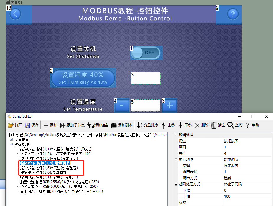
On the [Button Control] screen, for button controls ID4 and ID6, and text control ID5, the configuration interface does not directly associate with the controls. Add the following logic processing
Article 1: Purpose: For [button press], fill in the corresponding screen ID1 and button control ID4. The execution action is [incremental adjustment], the variable being adjusted is [set temperature], the adjustment step size is [1] (step size can only be an integer), and the adjustment method is [decremental]
Article 2: Purpose: For [control binding], fill in the corresponding screen ID1 and text control ID5, with the bound variable being [set temperature]
Article 3: Purpose: For [button press], fill in the corresponding screen ID1 and button control ID6. The execution action is [incremental adjustment], the variable being adjusted is [set temperature], the adjustment step size is [1] (step size can only be an integer), and the adjustment method is [incremental]
as shown below:
Run Preview
Based on the screen configuration and logic processing, combined with the Modbus slave debugging tool, when the button control (control ID: 1) is pressed, the state of the slave device is turned off. Similarly, button presses can also be used for saving register variable settings, incremental adjustment, and other functions. The running results are shown below

3.2 Text Control
On the [Text Control] screen, the text control is primarily used to display the bound variable values. For variables of read-write types such as coils and hold registers, the "Input Method" can be set to pop up a system keyboard for input, allowing modifications to the bound variable values through the popped-up keyboard. Additionally, it is possible to bind logic processing for modifying display colors and blinking
Screen/Logic Configuration
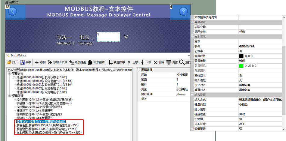
Screen. Add a text control (Control ID: 1) to display the voltage value; the input method is a pop-up keyboard. Add the following logic processing:
Item 1: Purpose is "Control Binding", binding variable "Voltage"
Item 2: Purpose is "Set Color", set the color to red (RGB (255, 0, 0)), with the execution condition being that the value of "Set Voltage" is greater than "250"
Item 3: Purpose is "Set Color", set the color to black (RGB (0, 0, 0)), with the execution condition being that the value of "Set Voltage" is less than or equal to "250"
Item 4: Purpose is "Text Flashing", with the execution condition being that the value of "Set Voltage" is greater than "250"
Run Preview
Display the real-time values of current and voltage. When the "Voltage" value is greater than 250, the text displays in red and flashes; if the "Voltage" value is less than or equal to 250, the text displays in black and does not flash, as shown below:

4 Gauge, Slider, and Progress Bar Controls
This chapter mainly introduces the common applications of gauge controls, slider controls, and progress bar controls in the Modbus protocol. Simple controls can be bound to variables, which can be associated on the configuration page or bound to variables in [Tools - Protocols and Variables - Logic Processing]
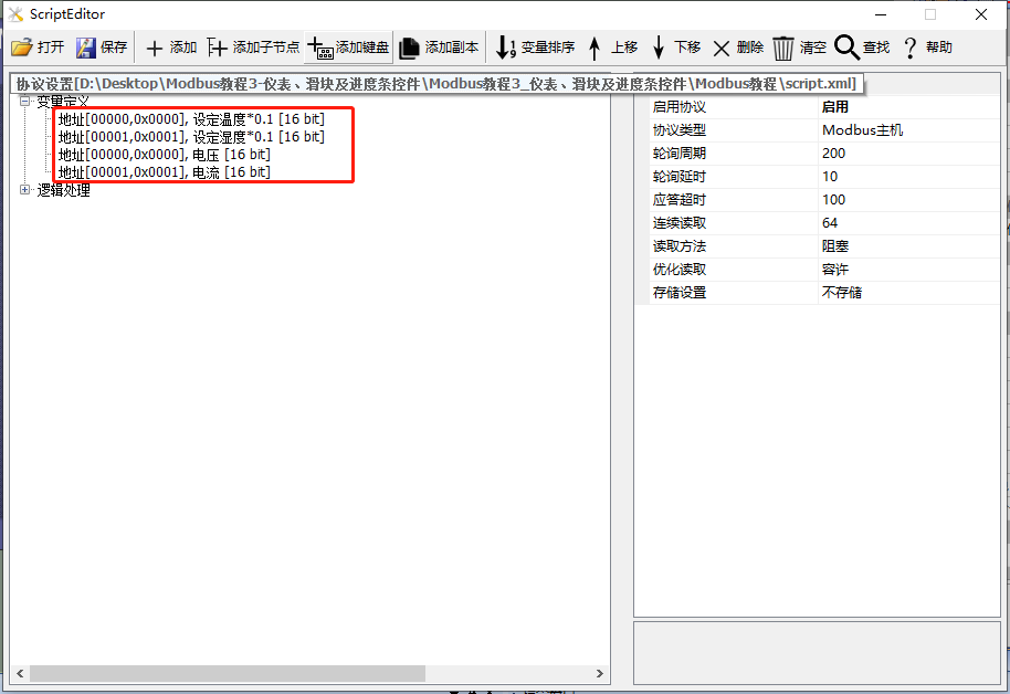
In this chapter, the screen acts as the master station, reading and writing slave device commands. If the screen acts as the slave station, the application of gauge, slider, and progress bar controls is the same, and reference can be made. This chapter creates 2 save registers and 2 input registers to illustrate the application of gauge controls, slider controls, and progress bars, as shown below.
Scope of application: Full series
Routine download link:Modbus Tutorial 3 - Gauge, Slider, and Progress Bar Controls V1.0(click to jump)
Protocol enablement and variable-related instructions, reference link:"Modbus Basic Parameter Description"
4.1 Gauge Controls
The [Instrument Controls] screen primarily provides demonstrations on the use of instrument controls. These controls reflect data changes on the user's host device, meeting the user's needs for an instrument interface
Screen/logic configuration
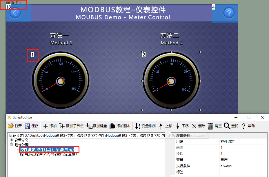
Method 1: Logic processing binding
Add a gauge control (Control ID: 1) to the screen to display the voltage value of the slave device. Open "Tools - Protocols and Variables" and add one logic processing
For the purpose of [control binding], fill in the corresponding screen ID1 and gauge control ID1. The bound variable is [voltage], as shown below
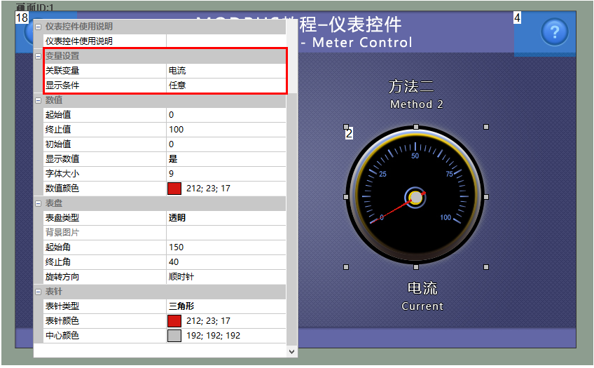
Method 2: Configure Screen Binding
Add a gauge control (Control ID: 2) to the screen to display the current of the slave device. Bind the "Current" variable in its property window, as shown below
Run Preview
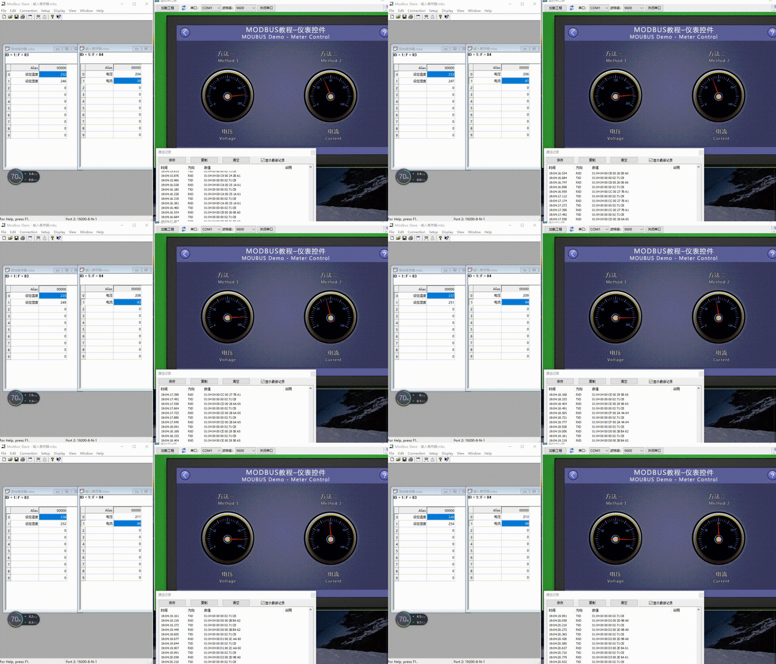
At this point, compile the project and run the virtual serial port screen, connect it to the Modbus Slave software, and the gauge control will display the changes in voltage (Control ID: 1) and current (Control ID: 2) in real time
4.2 Slider and Progress Bar Controls
[Progress Bar and Slider Controls] On the screen, the progress bar control and slider control are used together. The notification of the progress bar is associated with the slider, which is mainly used to display the bound variable value. By dragging the slider control's cursor, the variable value can be changed
Screen/Logic Configuration
Method 1: Logic Processing Binding
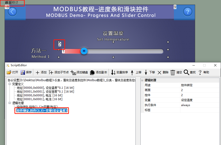
Add a progress bar control (control ID: 1) and a slider control (control ID: 2) to the screen. Add one logic processing in [Protocol and Variable Settings]
Usage: For [Control Binding], fill in the corresponding screen ID2 and gauge control ID2. The bound variable is [Set Temperature], as shown below
Method 2: Configure Software Binding
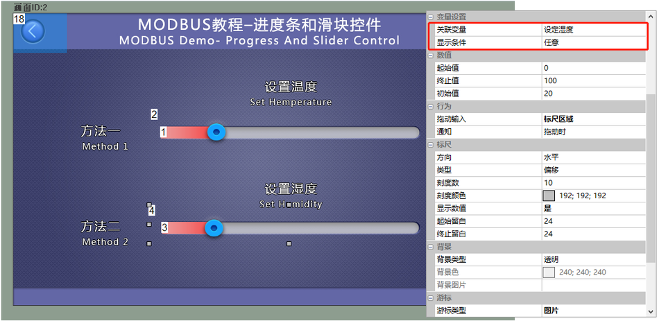
Add a progress bar control (control ID: 3) and a slider control (control ID: 4) to the screen. The slider control is directly bound to "Set Humidity". The configuration is as follows:
Run Preview
At this point, compile the project and run the virtual serial port screen, connecting it to the Modbus Slave software. When the value of the variable changes, the status displayed by the slider control and progress bar will be updated accordingly; by clicking and dragging the slider control with the mouse, the value of the variable will also be updated accordingly

5 Menu Control and Slider Selection Control
This section mainly introduces the common applications of slider selection control and menu control in the Modbus protocol. Simple controls can be bound to variables, which can be associated on the configuration page or bound to variables in "Tools - Protocol and Variables - Logic Processing"
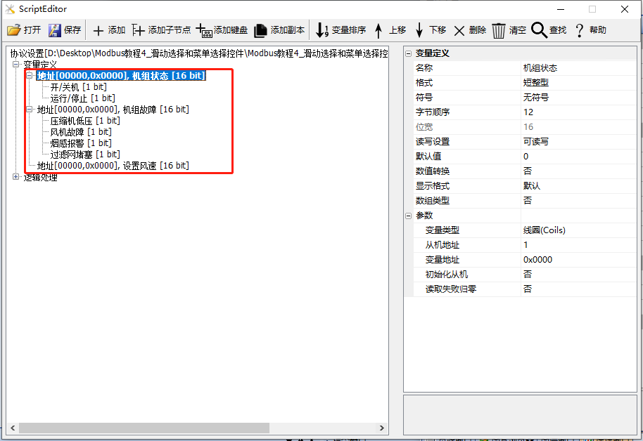
In this section, the screen acts as a master station, reading and writing slave instructions. If the screen acts as a slave, the application of slider selection control and menu control is the same, and can be referenced. This section creates two save registers to illustrate the application of slider selection control and menu control, as shown below
Scope of use: Full series
Example download link:"Modbus Tutorial 4_Slider Selection and Menu Selection Control V1.0.rar"
Protocol enablement and variable-related instructions, reference link:"Modbus Basic Parameter Description"
5.1 Menu Control
The [Menu Control] screen primarily provides an example of how to use menu controls. There are two types of "styles" for menu controls: "Pop-up Menu" and "Fixed Menu". Here, we mainly focus on the instructions for using the pop-up menu. When the "Menu Style" is set to "Pop-up Menu", a button control is required to associate the menu control with the text control. Clicking the button will pop up the menu control, and selecting a menu item will directly display it in the text control
Screen/Logic Configuration
Method 1: Logic Processing Binding
Add a menu control (Control ID: 2) to the screen as a control for switching the slave machine on and off. The detailed configuration is shown below
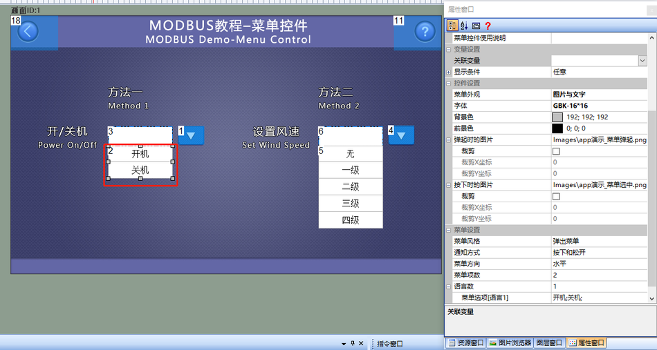
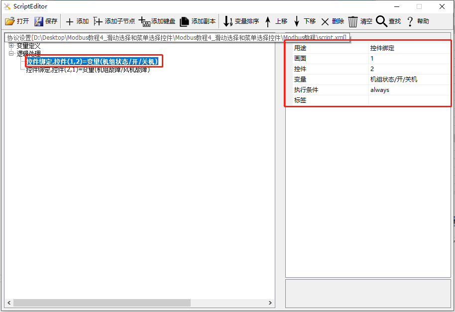
Add a logic processing in the "Protocol and Variable Settings", with the purpose of "Control Binding", the screen is "1"; the control is "2"; the variable is "Unit Status/On/Off", as shown below
Method 2: Configuration Screen Binding
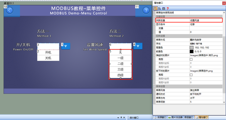
Add a menu control (Control ID: 5) to the screen as a control for controlling the wind speed of the slave machine. And bind the "Set Temperature" variable in its property bar window. The detailed configuration is shown below
Run Preview
At this point, compile the project and run the virtual serial port screen, and connect it with the Modbus Slave software. When the button control (Control ID: 4) is pressed, the pop-up menu control (Control ID: 5) appears. Selecting the "Level 1" option of the menu control will directly display "Level 1" in the text control (ID: 6), and the slave variable "Set Wind Speed" will change accordingly

5.2 Sliding Selection Control
On the "Slider Selection Control" screen, the selection control serves two primary purposes: "Slider Selection" and "Status Display". "Slider Selection" is primarily used for selecting preset options through sliding on the touch screen, while "Status Display" is mainly utilized for displaying various preset options, akin to an icon control
Screen/Logic Configuration
Method 1: Logical Processing Binding
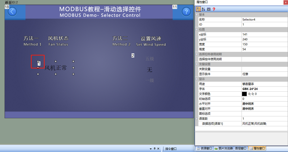
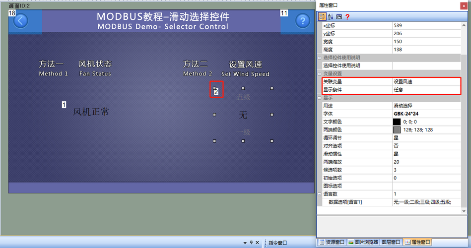
Add a sliding selection control (Control ID: 1) to the screen to display the fan status; the purpose is "Status Display", as shown below
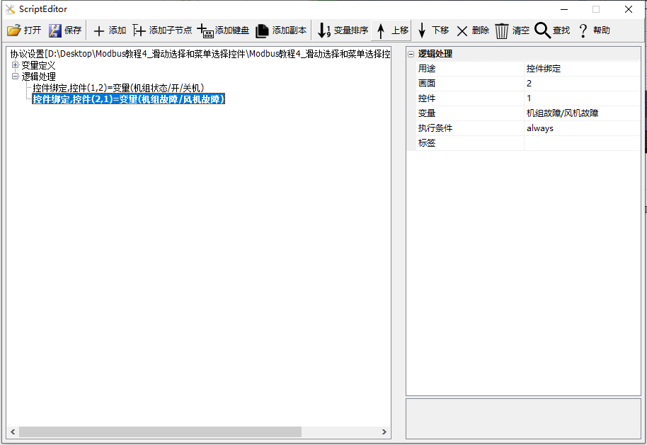
Add a logic processing in [Protocol and Variable Settings]: Purpose is "Control Binding"; Screen is "2"; Control is "1"; Variable is "Unit Status/Wind Turbine Fault".
Method 2: Configuration Screen Binding
Add a menu control (Control ID: 2) to the screen to control the wind speed level of the slave machine. Bind the "Set Wind Speed" variable in its property bar window, as shown below
Run Preview
At this point, compile the project and run the virtual serial port screen, connecting it to the Modbus Slave software. When the value of the variable "Unit Status/Fan Fault" changes, the status displayed by the sliding selection control (Control ID: 1) will be updated accordingly; by clicking and dragging the sliding selection control (Control ID: 2) with the mouse, when the dragging stops, a certain option will be selected, and the value of the variable "Set Wind Speed" will also be updated

6 Curve and Historical Curve Controls
This section mainly introduces the common applications of curve controls and historical curve controls in the Modbus protocol. Simple controls can be bound to variables, which can be associated on the configuration page or bound to variables in [Tools - Protocols and Variables - Logic Processing]
In this section, when the screen acts as a master station, it reads and writes slave machine instructions. If the screen acts as a slave machine, the application of curve controls and historical curve controls is the same, and can be referenced. This section creates two save registers to illustrate the application of curves and historical curves, as shown below
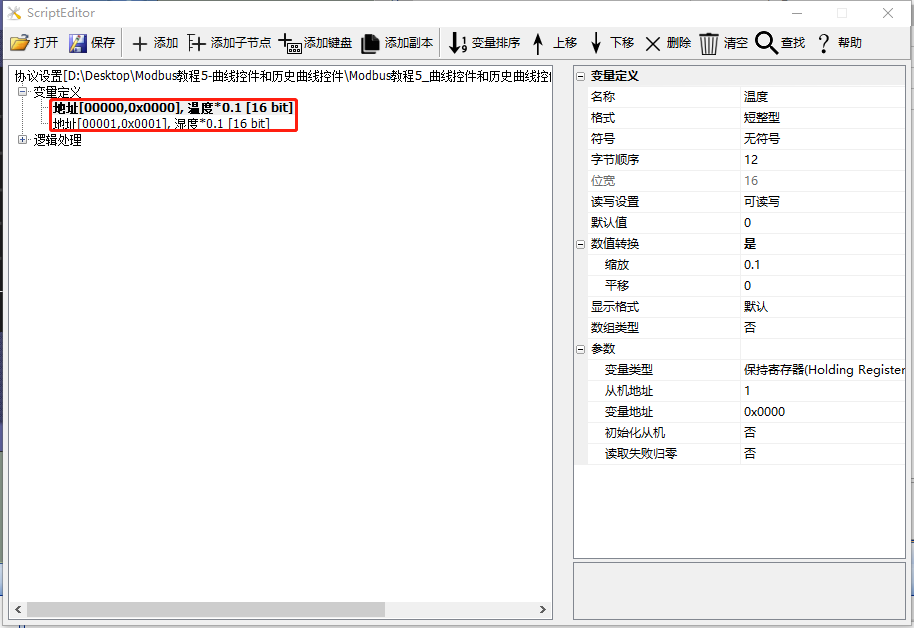
Scope of Application: Full Series
Example Download Link:"Modbus Tutorial - 5 - Curve and Historical Curve Controls V1.0"
Protocol startup, variable-related instructions, reference link:"Modbus Basic Parameter Description"
6.1 Curve Controls
The [Curve Control] screen primarily provides an example of how to use curve controls. In the MODBUS protocol version, the curve control is used to display associated variables. The curve control periodically samples the variable values and then plots all the sampled values into the curve control, connecting them to form a curve. Each channel of the curve control can be associated with one variable, and up to 8 channels can be set
Screen/Logic Configuration
Add a curve control (ID: 1) to the screen to display the "temperature" value of the slave device. Also add two button controls (IDs 2 and 4) as controls for increasing and decreasing the "temperature" variable, and add a text control (ID: 3) directly bound to "temperature" for numerical display. The relevant parameter configurations for the curve control are as follows:
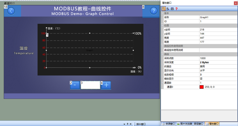
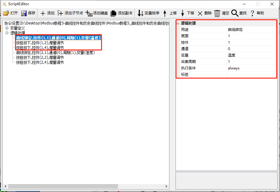
Add 3 logic processes in [Protocol and Variable Settings]:
First: Purpose is "Curve Binding", screen is "1"; control is "1"; channel is "0", variable is "temperature"; acquisition period is "1"
Second: Control the increase and decrease of "temperature". Purpose is "Button Pressed", fill in screen ID as 1, control ID as 2; execution action is "Incremental Adjustment", variable is "temperature", adjustment step size is "1", adjustment method is "Decrease"; adjust from 0 to 100 in a loop
Third: Control the increase of "temperature". Purpose is "Button Pressed", fill in screen ID as 1, control ID as 4; execution action is "Incremental Adjustment", variable is "temperature", adjustment step size is "1", adjustment method is "Increase"; adjust from 0 to 100 in a loop. As shown below:
Run Preview
At this point, compile the project and download it to the serial port display. Connect it with the MODBUS Slave software, and the curve control will display the real-time temperature changes. Pressing the button controls (ID: 2 and ID: 4) simultaneously allows control of the "temperature" variable, and the display of the curve control will change accordingly, as shown below

6.2 Historical Curve Control
The [Historical Curve Control] interface primarily provides demonstrations on the usage of historical curve controls. Both historical curve controls and regular curve controls are capable of real-time sampling and displaying bound variable values. The primary difference lies in the fact that historical curve controls store previous data, allowing users to view historical data. In the MODBUS protocol version, historical curve controls are utilized to display associated variable values. These controls periodically sample variable values, subsequently plotting all sampled values within the historical curve control to form a connected curve. Each channel of the historical curve control can be associated with a variable, with a maximum of 8 channels that can be set.
Screen/Logic Configuration
Add a historical curve control (ID: 1) to the screen to display the "humidity" value of the slave device. Also add two button controls (ID: 2 and 4) for controlling the increase or decrease of the "humidity" variable; and add a text control (ID: 3) directly bound to the "humidity" variable for numerical display. The relevant parameter configuration for the historical curve control is as follows
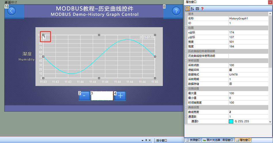
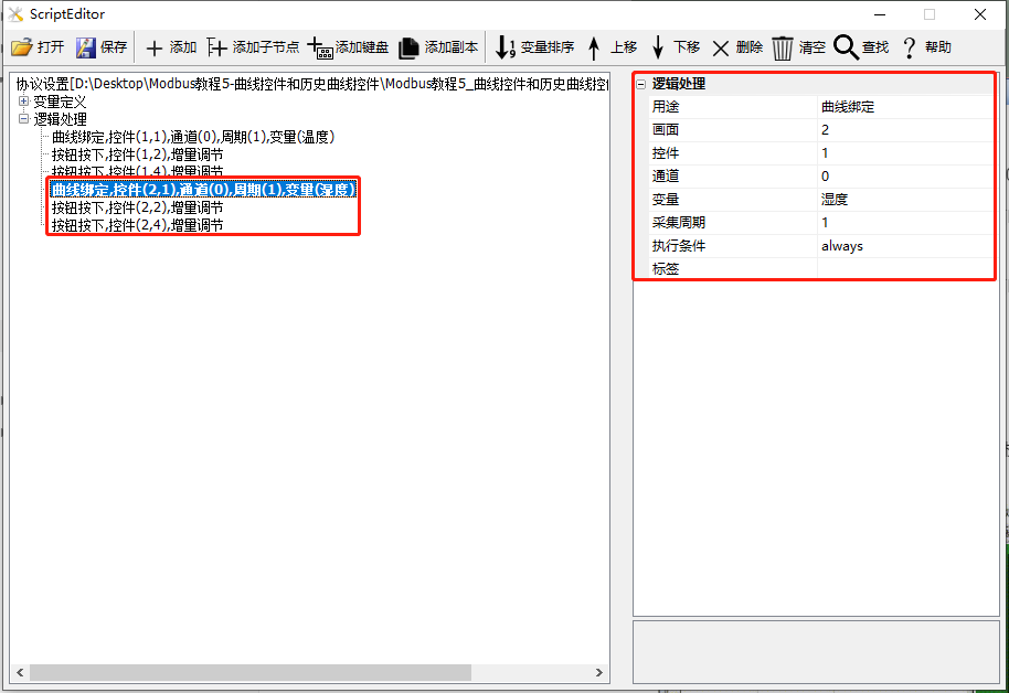
Add three logic processes in [Protocol and Variable Settings]:
First: Purpose is "Curve Binding", screen is "2"; control is "1"; channel is "0", variable is "humidity"; collection period is "1"
Second: Control the increase or decrease of "humidity". Purpose is "Button Pressed", fill in the screen ID as 2, control ID as 2; execution action is "Incremental Adjustment", variable is "humidity", adjustment step size is "1", adjustment method is "Decrease"; adjust from 0 to 100 in a loop
Third: Control the increase of "humidity". Purpose is "Button Pressed", fill in the screen ID as 2, control ID as 4; execution action is "Incremental Adjustment", variable is "humidity", adjustment step size is "1", adjustment method is "Increase";
Run Preview
At this point, compile the project and download it to the serial port display, then connect it to the MODBUS Slave software. The historical curve control will display the real-time changes in humidity. When the number of sampling points displayed on the screen exceeds the set value (default is 100), you can view historical data through the scroll bar above the historical curve control. Simultaneously pressing the button controls (ID: 2 and ID: 4) allows for the control of the "humidity" variable, and the display of the historical curve control will change accordingly

7 Icon controls and animation controls
This section mainly introduces the common applications of icon controls and animation controls in the Modbus protocol. Simple controls can be bound to variables, which can be associated on the configuration page or bound to variables in [Tools - Protocol and Variables - Logic Processing]
This section uses the screen as the master station to read and write slave instructions. If the screen acts as a slave, the application of icon controls and animation controls is the same and can be referenced. This section uses one set of discrete input variables and two input registers to illustrate the application of icon controls and animation controls, as shown below
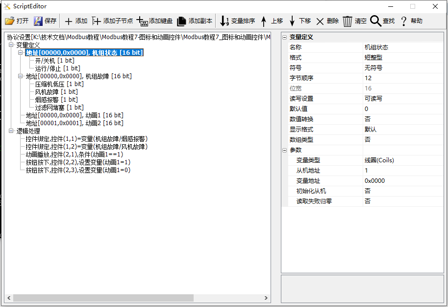
Scope of application: full series
Example download link:"Modbus Tutorial 7 - Icon and Animation Controls V1.0"
Protocol enablement and variable-related instructions, reference link:"Modbus Basic Parameter Description"
7.1 Icon Controls
The [Icon Control] screen primarily provides demonstrations on the usage of icon controls. Icon controls are animated files in GIF or ICON format, with the default icon index starting from 0. In the MODBUS protocol, icon controls can be used to bind variables, visually displaying the status of devices
Screen/Logic Configuration
Method 1: Logic Processing Binding
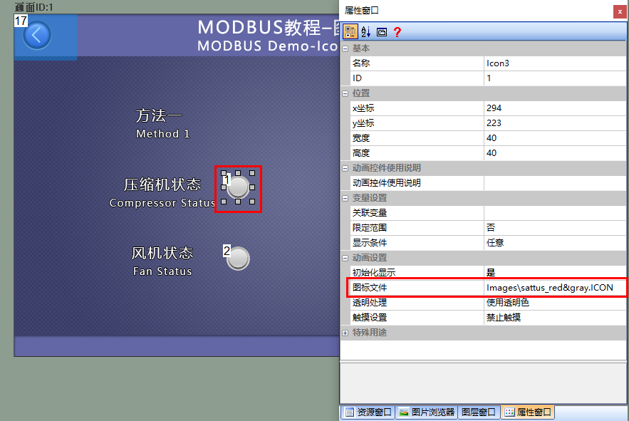
Add an icon control (control ID: 1) to the screen as a display for the slave's "unit fault/compressor status", as shown below
Control ID: 2, similar configuration
For the generation of icon files, refer to the link: "<ICON Control Application> (click to jump)"
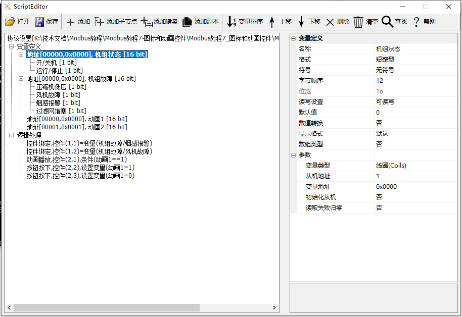
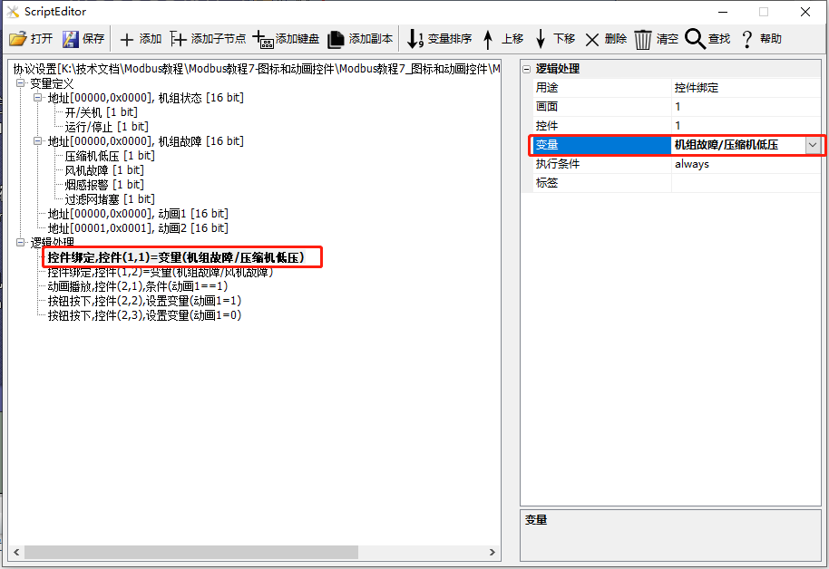
Add a logic processing in the "Protocol and Variable Settings", with the purpose of "Control Binding", and the screen is "1"; the control is "1"; the variable is "Unit Fault/Compressor Low Pressure", as shown below
Method 2: Configure Screen Binding
Add an icon control (Control ID: 3) in the screen to display the smoke alarm status of the slave machine. And bind the "Unit Fault/Smoke Alarm" variable in its property bar window, with detailed configuration as shown below
Control ID: 4, similar configuration
Run Preview
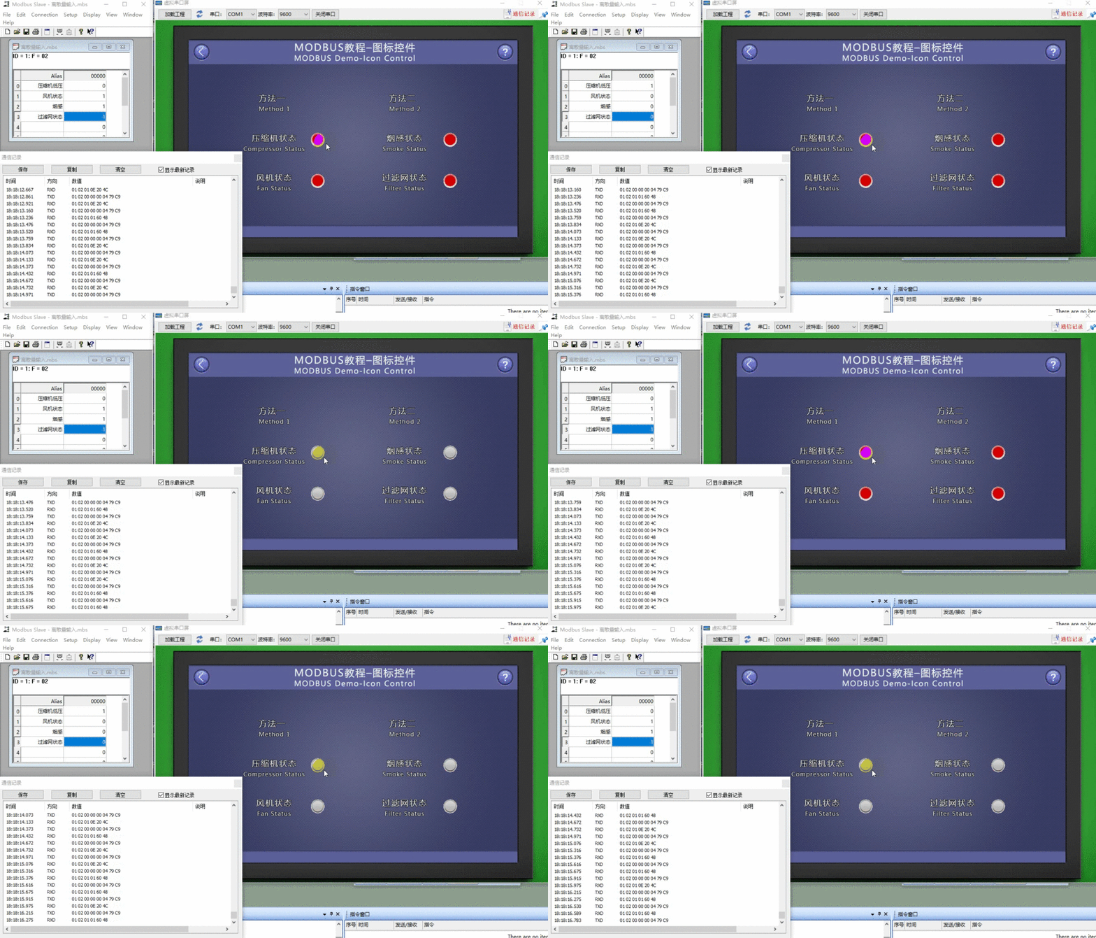
At this time, compile the project and run the virtual serial port screen, connecting with the Modbus Slave software. When the value of the "Unit Fault" variable changes continuously for each node, the display status of the icon controls (Control ID: 1~ID4) will be updated accordingly
7.2 Animation Control
The "Animation Control" screen mainly provides an example of the use of animation controls. Animation controls are used to play set GIF or ICON format animation files, and can be controlled to pause or play
Screen/Logic Configuration
Method 1: Logic Processing Binding
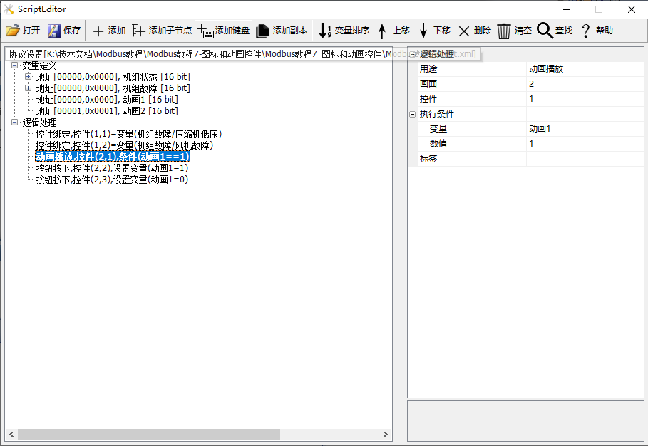
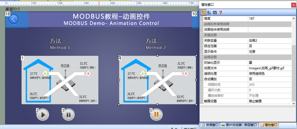
Add an animation control (Control ID: 1) to the screen as a display control for the "animation1" variable of the slave device; simultaneously, add two button controls (IDs 2 and 3) for controlling the playback and pause of the animation control (Control ID1), as shown below
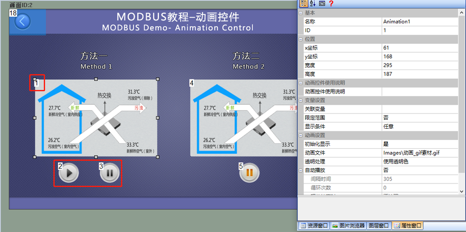
Add 3 pieces of logic processing in [Protocol and Variable Settings]:
First: Purpose is "animation playback", screen is "2"; control is "1"; and associated with "animation1"
Article 2: Control the playback of "animation". For the purpose of [button press], fill in the screen ID as 2 and the control ID as 2; the execution action is [set variable], the variable is [animation1], and the set value is 1
Article 3: Control the pause of "animation". The purpose is for [button press]. Fill in the screen ID as 2 and the control ID as 3; the execution action is [set variable], the variable is [animation1], and the set value is 0
Method 2: Configuration Screen Binding
Add an animation control (Control ID: 4) to the screen as a display control for the "animation2" variable of the slave device. Bind the "animation2" variable in its property bar window. Add a button control (ID: 5) for controlling the playback and pause of the animation control (Control ID4), as shown below
Run Preview
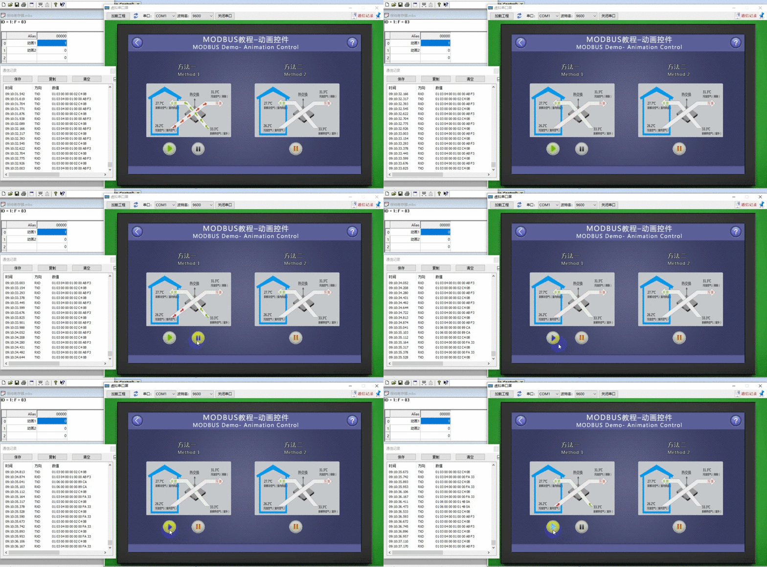
At this point, compile the project and run the virtual serial port screen, connecting it to the Modbus Slave software. When the value of the "animation1" variable is not "0", the animation control (Control ID: 1) plays the animation; meanwhile, clicking the button control (Control ID: 2 or 3) can control the animation control to "play" or "stop", and the value of the "animation1" variable changes accordingly. Similarly, the phenomenon and operation of the animation control (Control ID: 4) are similar.
8 QR Code Control and RTC Control
This section mainly introduces the common applications of QR code controls and RTC controls in the Modbus protocol. The QR code control is only supported in the "Tools - Protocols and Variables - Logic Processing" binding variable.
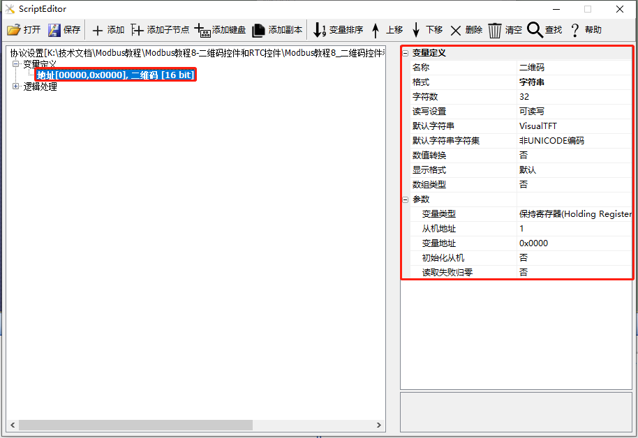
This section uses the screen as the master station and creates one save register for the application of the QR code control, as shown below.
Scope of application: Basic type - QR code special support, supported by other series.
Example routine download link:"Modbus Tutorial 8 - QR Code and RTC Controls V1.0"
For protocol activation and variable-related instructions, refer to the link:"Modbus Basic Parameter Description"
8.1 QR Code Control
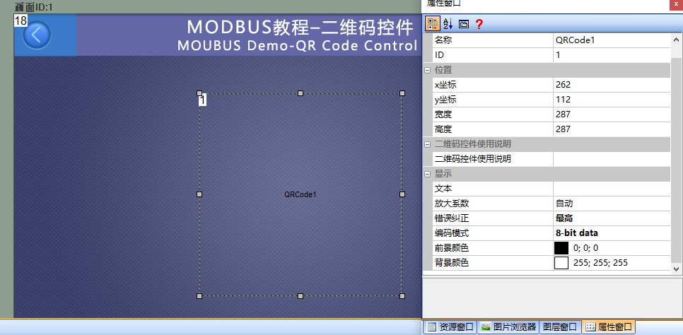
The "QR Code" screen mainly provides example instructions for using the QR code control. The QR code control can display a set string in the form of a QR code, which can be recognized by some scanning instruments.
Note: The basic type series of serial port screens require special firmware support for using the QR code control.
Screen/Logic Configuration
Add a QR code control (control ID: 1) to the screen, and configure the control properties as follows:
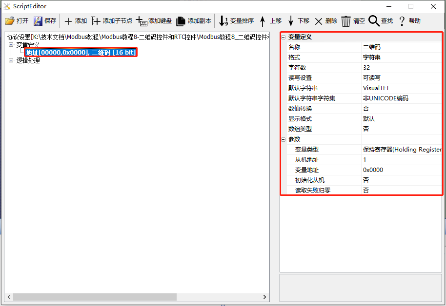
Add a variable in the "Protocol and Variable Settings" with a variable type of "String" and a string length of 32, as shown below
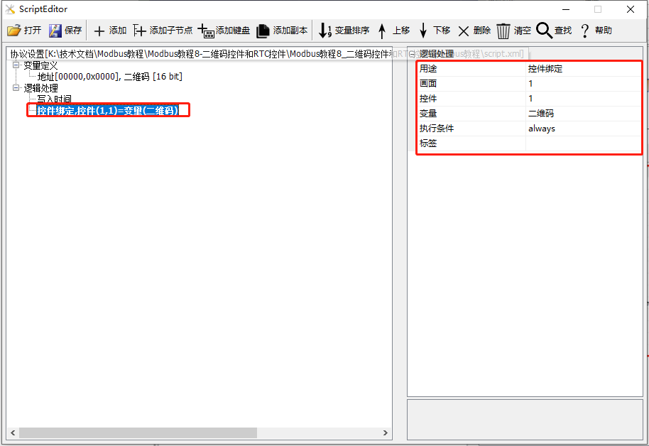
Add a logic processing in the "Protocol and Variable Settings" with the purpose of "Control Binding" and the screen being "1"; the control being "1"; the variable being "QR Code", as shown below
Run Preview
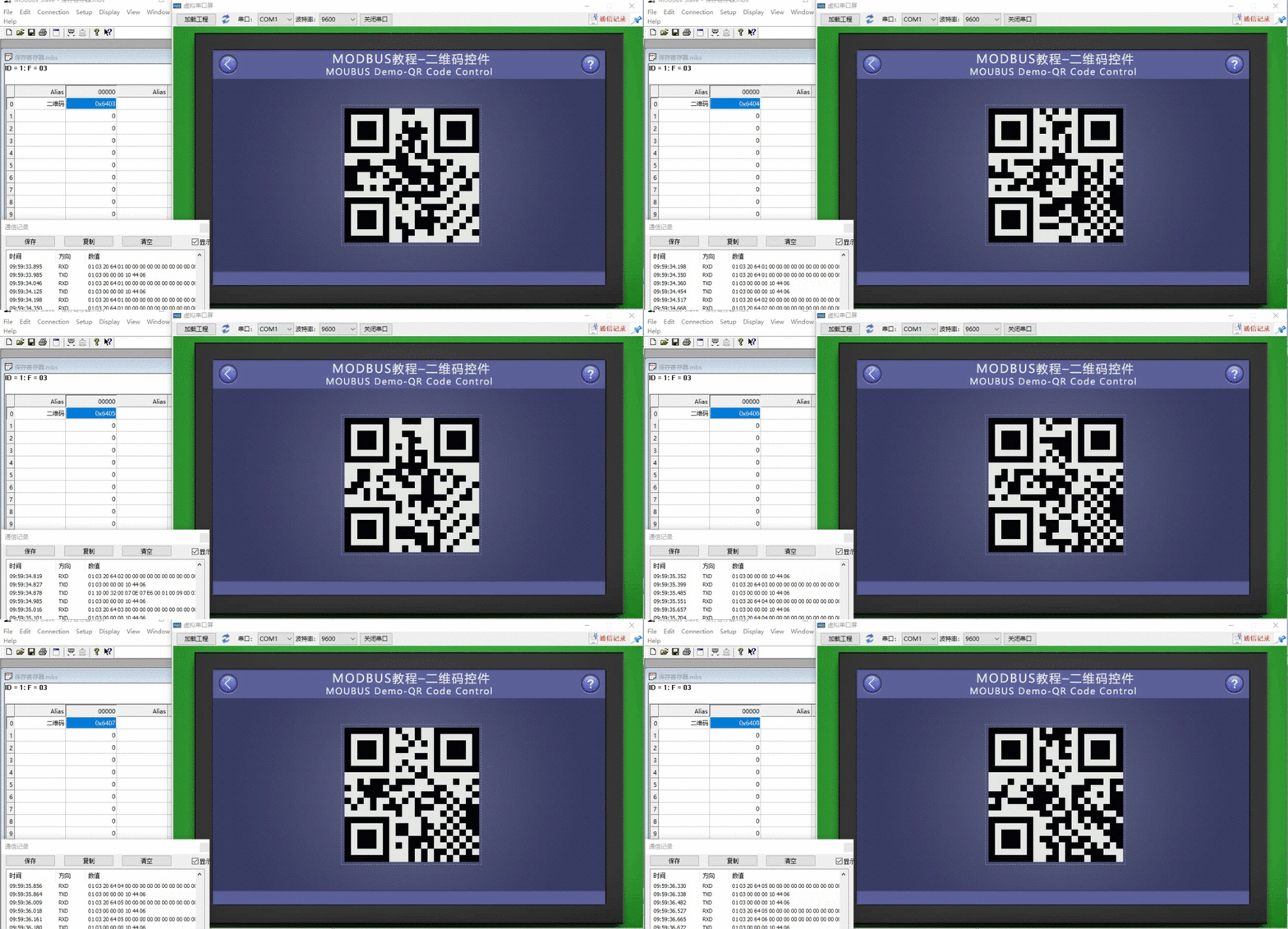
At this point, compile the project and run the virtual serial port screen. The QR Code control will display the string "VisualTFT" in the form of a QR Code. When connected to the Modbus Slave software, the QR Code control displays the corresponding string.
8.2 RTC Control
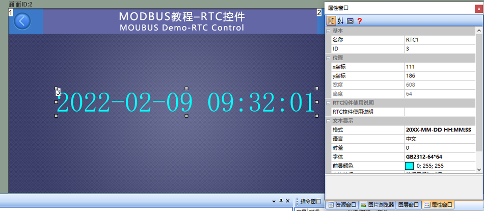
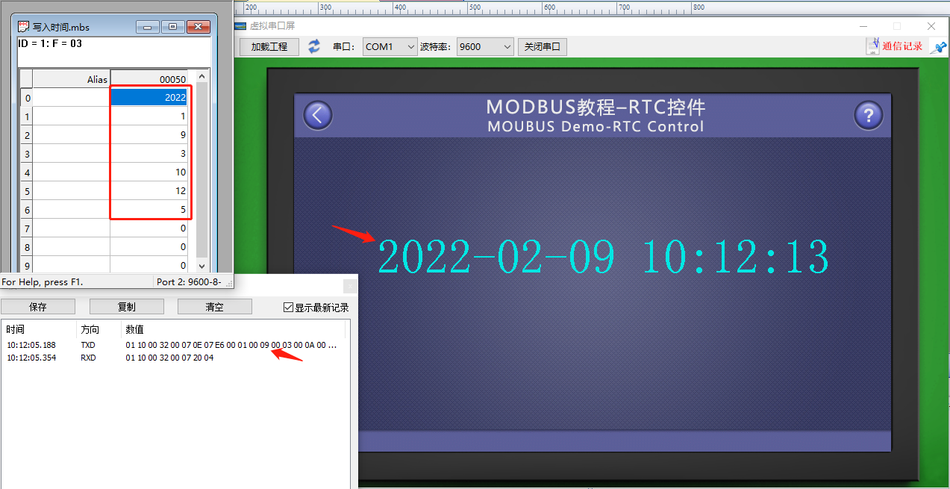
The "RTC Control" screen mainly provides an example of how to use the RTC control. When the screen acts as the master, it modifies the RTC time of the slave; the slave creates fixed-address holding registers to store time variables, with seven consecutive holding registers storing year, month, week, day, hour, minute, and second. The screen periodically writes the latest time to the slave registers through the 0x10 command
Screen/Logic Configuration
Add an RTC control (control ID: 1) to the screen, as shown below:
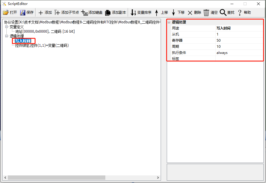
Add a logic processing in the "Protocol and Variable Settings": purpose being "Write Time"; slave address being "1"; register being "50" (decimal); cycle being "10" (unit: seconds), as shown below:
Run Preview
At this point, compile the project and run the virtual serial port screen. When connected to the Modbus Slave software, the master sends the RTC time to the slave every 10 seconds.
9 Control Display Hiding and Multi-Language Function
This section mainly introduces the display and concealment of controls, as well as the application of multiple languages. Among them, only configuration controls support display and concealment. For types of configuration controls, refer toIntroduction to VisualTFT Work Interface. Controls that support multiple languages include text, buttons, menus, slider selection, data logging (alarms), and so on.
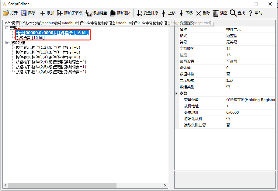
In this section, the screen serves as the master station. A save register is created to control the display and concealment of configuration controls; a system variable is created for language control selection, as shown below.
Scope of application: Full series.
Routine download link:"Modbus Tutorial 9 - Control Concealment and Multiple Languages V1.0".
For protocol activation and variable-related descriptions, refer to the link:"Modbus Basic Parameter Description".
9.1 Control Display and Concealment
The screen mainly provides example explanations for the use of the control display and concealment function. It demonstrates the application of concealing or displaying one or some controls when certain conditions are met.
Screen/Logic Configuration
Add a text control (Control ID: 1) to the screen to control the hiding and showing of controls. Add a progress bar control (Control ID: 1), a gauge control (Control ID: 2), and a text control (Control ID: 3) to be displayed or hidden, as shown below
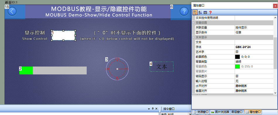
Add three logic processes in [Protocol and Variable Settings]: The first one: Purpose is "Control Display"; Screen is "1"; Control is "2"; Execution condition is "Variable [Control Display] is not 0". Similarly, the second and third settings are similar
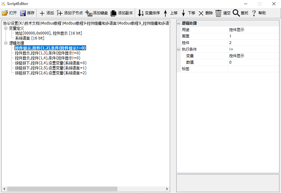
.
Run a preview. At this point, compile the project and run the virtual serial port screen, establishing a connection with the Modbus Slave software. When the value of the variable "Control Display" is "0", the slider control (Control ID: 2), gauge control (Control ID: 3), and text control (Control ID: 4) are hidden; when the value of the variable "Control Display" is "1", these controls are displayed. Meanwhile, clicking the text control (Control ID: 1) pops up a keyboard to enter "0" or "1" to control the display or hiding of the control.

9.2 Multi-language
The "Multi-language Function" screen mainly demonstrates the use of multi-language functionality. For different customers, multi-language applications are required. The screen supports multi-language settings for text, menu controls, and slider selection controls. The project uses three buttons to control the display of Chinese, English, and Traditional Chinese for text, menu controls, and slider selection controls.
Screen/Logic Configuration
Add a text (ID: 1), slider selection control (Control ID: 2), and menu control (Control ID: 3) to the screen for displaying different languages. Taking the text control as an example, the control property settings are as follows
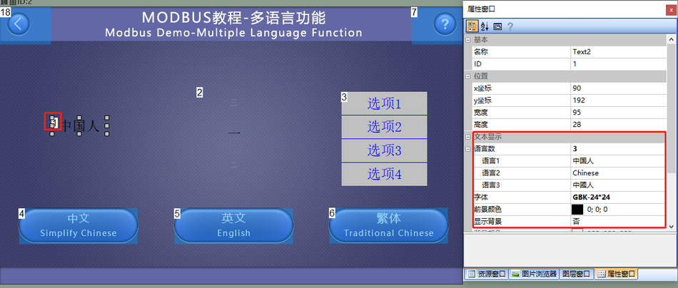
. Add three button controls (Control ID: 4, 5, 6) to the screen for controlling the display of different languages.
Button controls ID4~6 have been implemented with a mutual exclusion feature (only one can be selected at a time; refer to"Configuration Control Tutorial - Button Control" Section 1.3: Button Mutex)
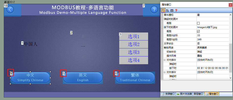
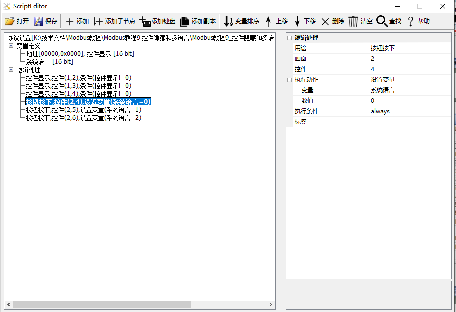
Add three logic processes to [Protocol and Variable Settings]: The first one has a purpose of "Button pressed"; the screen is "2"; the control is "4"; the execution condition is "Set [System Language] to 0", corresponding to the display of "Language 1". Similarly, the second and third settings are as follows:
Run Preview
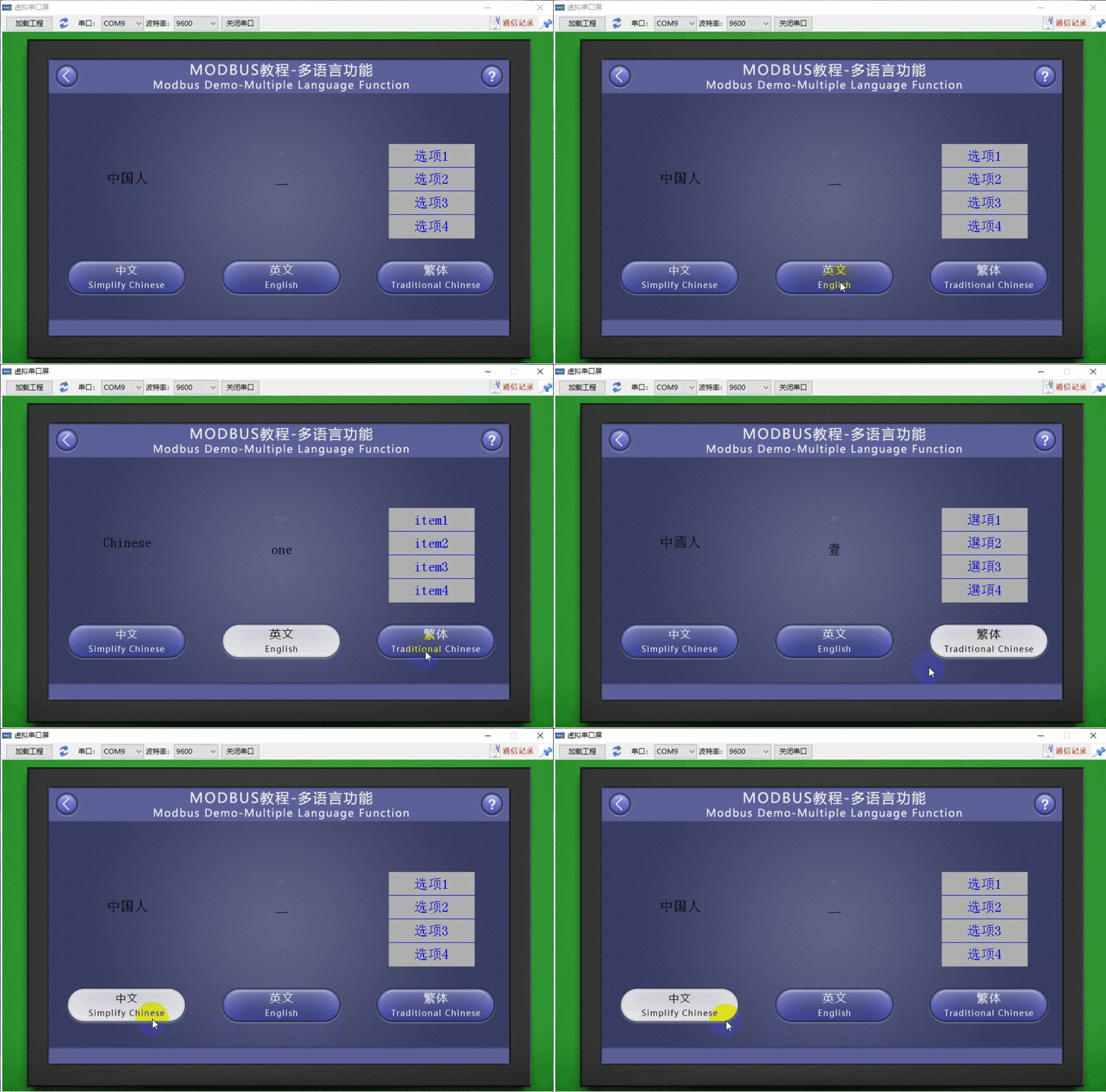
At this time, compile the project and run the virtual serial port screen, connecting it with the Modbus Slave software. When the button control (control ID: 1) is pressed, it displays Chinese; when the button control (control ID: 5) is pressed, it displays "English"; and when the button control (control ID: 5) is pressed again, it displays "Traditional Chinese"


Leave a Reply