
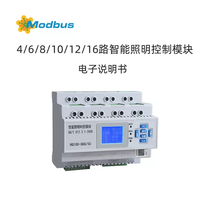
Product Overview
The HQ100 series intelligent lighting time control module is a high-performance lighting control system core device that integrates intelligence, automation, and safety. Intended to provide efficient, energy-saving, and convenient lighting management solutions for various commercial, industrial, and public facilities. This product achieves precise automation control of lighting circuits through advanced control algorithms and rich functional integration, thereby achieving the goals of energy conservation, reducing operation and maintenance costs, improving management efficiency, and ensuring emergency safety.
2, Feature Highlights
This product has the following nine core functions, fully meeting the diverse lighting control needs:
- Manual control: Supports on-site manual operation, convenient debugging and emergency response.
- Time Control: The switch time can be freely set, and multiple sets of timing can be set for each circuit, supporting automatic cycles with "week" as the cycle.
- Scene Control: Multiple lighting scenes can be preset (such as day, night, and late night modes), with one click switching.
- Fire Feedback: Receive feedback signals from the fire protection system and monitor the fire status in real-time.
- Fire linkage: In emergency situations, receiving a 24V signal from the fire protection system can forcibly light up all emergency circuits, ensuring smooth passage of life.
- RS485 Communication: Supports standard RS485 bus communication, can easily connect to building automation systems, and achieve centralized management.
- Longitude and latitude control: Built in precise longitude and latitude algorithms can automatically calculate sunrise and sunset times based on the geographical location, achieving fully automatic control of "resting at sunrise and working at sunset" without the need for manual adjustment of seasonal time.
- Light Sensing ControlExternal photosensitive sensor, automatically controlled according to ambient light intensity. Automatically turn on the lights when it gets dark (below the set threshold) and turn off the lights when it gets light (above the set threshold).
- 50A high powerThe maximum carrying current of a single circuit is 50A, with strong driving capability, which can meet the requirements of high-power lighting loads.
3, Detailed technical parameters
| Product model | HQ100-SK8/50, HQ100-SK16/50, etc. (supporting 4/6/8/10/12/16 circuits) |
| Working voltage | AC220V ±10% |
| Working current | 50A |
| Power consumption | ≤ 8W |
| Control action time | ≤ 0.5s |
| Communication method | RS485 bus |
| Appearance size | 8 circuits: 137 * 116 * 91mm; 16 circuits: 256 * 116 * 91mm |
| Installation method | Installation of 35mm standard guide rail |
| Environmental temperature | -20℃ ~ +60℃ |
| Display type | Digital display/LCD model (with backlit LCD screen, displaying time, date, sunrise and sunset information) |
4, Detailed explanation of main functional applications
- Intelligent timing control
- •FunctionUsers can freely set up to multiple on/off time points for each lighting circuit.
- •Application Case: Large shopping malls and office buildings. Different on/off strategies can be set for weekdays and weekends, such as turning on lights at 18:00 in the evening, turning off some lights at 02:00 at midnight, and turning off all lights at 06:00 in the morning.
- Longitude and latitude control (astronomical clock)
- •FunctionBy entering the latitude and longitude information of the location, the device can automatically adjust the daily light on/off time based on astronomical data, achieving synchronization with sunrise and sunset.
- •Advantages: No need to frequently modify schedules due to seasonal changes, achieving true "year-round unmanned operation".
- •Example: In summer (such as June 1st), turn on the lights at 19:56 at sunset and turn off the lights at 06:05 the next day at sunrise; In winter (such as December 1st), turn on the lights at sunset at 17:06 and turn off the lights at sunrise at 06:25 the next day.
- Light Sensing Control
- •Function: The ambient brightness is detected through an external light control probe as a triggering condition for the on/off light.
- •Application: It can automatically turn on the lights during dimly lit days such as rainy weather, making up for the shortcomings of pure time control or latitude and longitude control, and is more intelligent and user-friendly.
- Fire linkage
- •Function: When receiving a 24V passive linkage signal from the fire center, the module will forcibly light up all preset emergency lighting circuits to ensure sufficient lighting in evacuation routes.
- •Safety ValueThis function is a critical component of fire safety, complying with safety regulations and providing lighting support for personnel evacuation in emergency situations.
5, Widely applicable scenarios
This system is suitable for almost all occasions that require intelligent lighting management, including but not limited to:
- •Commercial space: Large shopping centers, star rated hotels
- •Public buildingsSchools, hospitals, and office buildings
- •Cultural and Tourism Real EstateTheme parks, villa areas
- •InfrastructureUnderground parking lot, urban road lighting, park landscape lighting
6, Product appearance and interface description (based on LCD model)
- •LCD display screenDisplay current time, date, sunrise and sunset time, operating status, etc.
- •Control buttons (K1-K4)Used for parameter settings, mode switching, data shifting, confirmation, and other operations.
- •Indicator light area: Display status such as "Running", "Communication", "Fault", etc.
- •Wiring Terminal: including live wire input, load output, DC12V power input, RS485 communication interface, fire linkage/feedback interface, optical control probe interface, etc. Summary: The HQ100 series intelligent lighting time control module has become an ideal choice for modern intelligent lighting systems due to its powerful functions, stable performance, and convenient management. It can significantly improve the intelligence level of lighting management, achieve efficient energy-saving effects, and ensure fire safety in emergency situations. It is the preferred control component for building green, intelligent, and safe buildings.
7, Summary
The HQ100 series intelligent lighting time control module has become an ideal choice for modern intelligent lighting systems due to its powerful functions, stable performance, and convenient management. It can significantly improve the intelligence level of lighting management, achieve efficient energy-saving effects, and ensure fire safety in emergency situations. It is the preferred control component for building green, intelligent, and safe buildings.
Wiring Diagram
Communication Protocol
1, ModBus Basic Rules
All RS485Communication circuits should follow both master and slave modes. According to, data can be transmitted between a main station (such as PC) and 128 sub stations.
No communication can start from the substation. All communication on the RS485 circuit is transmitted in the form of "information frames". If the main or sub station receives an information frame containing an unknown command, it will not respond.
In RS485All communication on the circuit is transmitted in the form of "information frames".
If the main or sub station receives an information frame containing an unknown command, it will not respond.
2, Data Frame Format
Communication transmission is asynchronous and measured in bytes (data frames). Every transmission between the main station and sub stations data frame is a serial data stream of 11 bits.
Data Frame Format
| Start Bit | 1 Bit |
| Data Bit | 8 Bits |
| Parity Check Bit | Optional Odd, Even, or Ineffective |
| Stop Bit | Ineffective 2 Bits, Valid 1 Bit |
| Baud Rate | 2400 , 4800, 9600bps |
3, When a communication command is sent to a module, the module that matches the corresponding address code receives the communication command, removes the address code, and reads the information. If there are no errors, the corresponding task is executed, and then the result of executing
When a communication command is sent to a module, the module that matches the corresponding address code receives the communication command and removes the address code, Read the information, if there are no errors, execute the corresponding task, and then execute itis returned to the sender. The returned message includes the address code, the function code for executing the action, the data after executing the action, and the error checkcode (CRC ). If there is an error, an error message will be returned.
Information Frame Format
| Initial Structure | Address Code | Function Code | Data Area | Error Check | End Structure |
| Delay (equivalent to3.5 bytes) | 1Byte 8Position | 1Byte 8Position | NByte N*8 Position | 2Byte16 Bit | Delay (equivalent to3.5bytes time |
Address code (Address):The address range of a single module is 1-247.
Function Code: The function code is the second data transmitted in each communication CODE: The function code is transmitted during each communication. If the highest bit of the function code returned by the child machine is 1 (function code>127), it indicates that the child machine is responding or the data isincorrect. The following table lists the specific meanings and operations of function codes.
| Function Code | Definition | Operation |
| 01H | Read Coil | Read Single or Multiple Loop Output States |
| 05H | Write Single Coil | Control Single Loop Output |
| 0FH | Write Multiple Coils | Control Multiple Loop Output |
| 03H | Read Register | Read Single or Multiple Register |
| 06H | Write Single Register | Write Single Register Data |
| 10H | Write Multiple Register | Write Multiple Register Data |
4, CRC-16 Code Calculation Steps
a) Set 16 Bit CRC Register to Hexadecimal FFFF ;
b)Subtract a8bit data from the low8bit of the CRC register and place the result in the CRC register;
c)Move the contents of the CRC register to the right by one bit, fill the highest bit with0, andcheck the shifted bit;
d)If the lowest bit is0: Repeat step3(shift) ;
e again)If the lowest position is1XOR CRC register with hexadecimal number A001;
f) Repeat steps3And4Until it moves to the right8Next time, this is the whole thing8All data has been processed;
g) Repeat steps2to5, proceed to the next data processing;
h) The final CRC register value obtained is the CRC code, which will be low during transmission8Send first, high8At the endsend out; Note: The calculation of CRC code starts from<child machine address>and includes all bytes except for<CRC code>.
5Example of Information Frame Format
5.1 Function code 01H: Reading coil status (reading circuit switch status)
- •Main station request message format:Address code function code starting address high starting address low number of coils high number of coils low CRC low CRC high 1 byte 01H1 byte 1 byte 1 byte 1 byte 1 byte 1 byte 1 byte 1 byte
- •Slave response message format:Address code function code data byte count data 1 (loop 1-8 status) Data nCRC low CRC high 1 byte 01H1 byte 1 byte . 1 byte 1 byte 1 byteNote: MSB represents the high byte of double byte count; LSB represents the low byte of the double byte count.
5.2 Function code 05H: Write a single coil (forced single circuit switch)
- •Main station request message format:Address code function code output address high output address low output value high output value low CRC low CRC high 1 byte 05H1 byte 1 byte 1 byte 1 byte 1 byte 1 byte 1 byte 1 byte
- •Slave response message format:Address code function code output address high output address low output value high output value low CRC low CRC high 1 byte 05H1 byte 1 byte 1 byte 1 byte 1 byte 1 byte 1 byte 1 byte(The slave sends back the original request message as a response)
5.3 Function code 0FH: Write multiple coils (forced multi circuit switch)
- •Main station request message format:Address code function code starting address high starting address low number of coils high number of coils low number of data bytes data 1... data nCRC low CRC high 1 byte 0FH1 byte 1 byte 1 byte 1 byte 1 byte 1 byte 1 byte 1 byte . 1 byte 1 byte 1 byteNote: When the data n is less than 8 bits, the high-order byte is filled with 0.
- •Slave Station Response Message Format:Address Code Function Code Starting Address High Starting Address Low Number of Coils High Number of Coils Low CRC Low CRC High 1 Byte 0FH1 Byte 1 Byte 1 Byte 1 Byte 1 Byte 1 Byte
5.4 Function Code 03H: Read and Hold Register
- •Master Station Request Message Format:Address Code Function Code Starting Address High Starting Address Low Number of Recordings High Number of Recordings Low CRC Low 1 Byte 03H1 Byte 1 Byte 1 Byte 1 Byte 1
- •Slave Station Response Message Format:Address code function code data byte count data 1 high data 1 low Data n high data n low CRC low CRC high 1 byte 03H1 byte 1 byte 1 byte 1 byte 1 byte 1 byte 1 byte
5.5 Function code 06H: Write to a single register
- •Main station request message format:Address code Function code Register address High register address Low data High data Low CRC Low CRC High 1 byte 06H1 byte 1 byte 1 byte 1 byte 1 byte 1 byte 1 byte 1 byte
- •Slave station response message format:Address code Function code Register address High register address Low data High CRC Low CRC High 1 byte 06H1 byte 1 byte 1 byte 1 byte(The slave sends back the original request message as a response)
5.6 Function code 10H: Write multiple registers
- •Main station request message format:Address code function code starting address high starting address low register quantity high register quantity low data byte quantity data 1 high data 1 low .. Data n high data n low CRC low CRC high 1 byte 10H1 byte 1 byte 1 byte 1 byte 1 byte 1 byte 1 byte 1 byte 1 byte 1 byte 1 byte 1 byte 1 byte 1 byte 1 byte
- •Slave response message format:Address code function code starting address high starting address low register quantity high register quantity low CRC low CRC high 1 byte 10H1 byte 1 byte 1 byte 1 byte 1 byte 1 byte 1 byte
4, Error code handling
If the data address or value sent by the master station is incorrect, the slave station will send back an error message. The highest digit of the returned function code is 1(Add 128 to the original function code). Slave returns error frame format:
| Address code | Function code (original function code+80H) | Error code | CRC low | CRC high |
|---|---|---|---|---|
| 1 byte | 1 byte | 1 byte | 1 byte | 1 byte |
Error code definition:
- •01:Illegal function codes. The received function code is invalid.
- •02:Illegal data address. The received data address exceeds the allowed address range.
- •03:Illegal data value. The received data value exceeds the data range of the corresponding address.
5, Register address and function description
7.1 Output status of each circuit in the module
- •Explanation:This set of registers maps the switch states of the physical circuit.
- •Operation:can be read using the 01H instruction, or written using the 05H (single channel) or 0FH (multiple channel) instructions.
- •Note:can use broadcast address (0x00) plus 05H or 0FH instructions to batch write to all modules.
7.2 Module Status Register
- •Description:is used to read various operational status information of the module.
7.3 Module Real time Clock Information Register
- •Description:is used to read or set the real-time clock (year, month, day, hour, minute, second, week) inside the module.
7.4 Module Installation Location Information Register
- •Description:can write text information describing the installation location of the module for easy identification.
7.5 Timing Control Register
- •Explanation:divides a day into 96 time periods (every 15 minutes). Each time period controls data to occupy 4 registers, totaling 8 bytes, defining the control actions for that time period.
- •Important operation restrictions:
- • The number and address of reads or writes to the timing control register group must be4 or a multiple of 4(i.e. at least one complete time period per operation).
- • A single read/write operation can only read/write up to 30 segments ofdata (i.e. 120 registers). The operation of all 96 data segments needs to be carried out multiple times.Data (i.e. 120 registers). The operation of all 96 data segments needs to be carried out multiple times.
7.6 Time Period Object Holiday Control Register
- •Description:Used to set holiday special control strategies based on time periods.
7.7 Loop Object Holiday Control Register
- •Explanation:Used to set holiday special control strategies based on circuits.
7.8 Remote Control Register
- •Address: 0x0E00
- •Operation:Use06HThe function code writes specific parameters to this register to immediately control the circuit switch.
- •Data format:
- •High 8 digits:
0xFFIndicate 'on',0x00Indicate 'closed'. - •Lower 8 digits:Use
0x01-0x10Indicate the specific circuit (1-16), using0xFFRepresents all circuits.
- •High 8 digits:
- •Control Example:
- • Write to Unit 0x0E00
0xFFFFForFully openWrite in0x00FFForAll off. - Write to Unit 0x0E00
0xFF01ForThe first circuit is openWrite in0x0001ForThe first circuit is closed. - Write to Unit 0x0E00
0xFF10ForThe 16th circuit is openWrite in0x0010ForThe 16th circuit is closed.
- • Write to Unit 0x0E00
Communication Protocol Example
| 01 Function Code | |
| 01 00 00 00 01 FD CA | Read 01 Channel Status |
| 01 01 00 01 00 01 AC 0A | Read the status of route 02 |
| 01 01 00 02 00 01 5C 0A | Read the status of route 03 |
| 01 01 00 03 00 01 0D CA | Read the status of route 04 |
| 01 01 00 04 00 01 BC 0B | Read the status of Route 05 |
| 01 01 00 05 00 01 ED CB | Read the status of Route 06 |
| 01 01 00 06 00 01 1D CB | Read the status of route 07 |
| 01 01 00 07 00 01 4C 0B | Read the status of route 08 |
| 01 01 00 08 00 01 7C 08 | Read the status of route 09 |
| 01 01 00 09 00 01 2D C8 | Read the status of 10 channels |
| 01 01 00 0A 00 01 DD C8 | Read the status of 11 channels |
| 01 01 00 0B 00 01 8C 08 | Read the status of 12 channels |
| 01 01 00 0C 00 01 3D C9 | Read the status of 13 channels |
| 01 01 00 0D 00 01 6C 09 | Read 14 circuit states |
| 01 00 0E 00 01 9C 09 | Read 15 circuit states |
| 01 01 00 0F 00 01 CD C9 | Read 16 circuit states |
| 01 00 02 00 03 DD CB | Read 02 circuit to start 3 circuit states |
| 01 00 00 08 3D CC | Read all 8 circuit states |
| 01 00 00 00 09 FC 0C | Read all 9 circuit states |
| 01 00 00 00 10 3D C6 | Read all 16 circuit states |
| 03 Function code | |
| 01 03 0A 00 01 87 D2 | Read status information data |
| 01 03 0A 01 00 01 D6 12 | Read port status data |
| 01 03 0A 00 0D 87 D7 | Read status, clock, and position information data |
| 01 03 0A 02 00 06 67 D0 | Read real-time clock data |
| 01 03 0A 07 00 01 36 13 | Reading Seconds |
| 01 03 0B 00 00 04 46 2D | Reading Period 1 Parameter |
| 01 03 0B 04 00 04 07 EC | Reading Period 2 Parameter |
| 01 03 0B 00 78 47 CC | Reading Period 1 Parameter |
| 01 03 0F 00 04 47 1D | Read Time Period 1 Parameters |
| 01 03 0F 04 00 04 06 DC | Reading Period 2 Parameter |
| 01 03 0F 00 78 46 FC | Read parameters from time slot 1 to 30 |
| 01 03 0F 78 00 78 C6 E5 | Read parameters from time slot 31 to 60 |
| 01 03 0F F0 00 78 46 CF | Read parameters from time slot 61 to 90 |
| 01 03 10 68 00 18 C0 DC | Read parameters from time period 90 to 96 |
| 05 Function Code | |
| 01 05 00 00 FF 00 8C 3A | Open Route 01 |
| 01 05 00 00 00 00 CD CA | Close Route 01 |
| 01 05 00 01 FF 00 DD FA | Open Route 02 |
| 01 05 00 01 00 00 9C 0A | Close Route 02 |
| 01 05 00 02 FF 00 2D FA | Open Route 03 |
| 01 05 00 02 00 00 6C 0A | Close Route 03 |
| 01 05 00 0B FF 00 FD F8 | Open Route 12 |
| 01 05 00 0B 00 00 BC 08 | Close Route 12 |
| 01 05 00 0F FF 00 BC 39 | Open route 16 |
| 01 05 00 0F 00 00 FD C9 | Close Route 16 |
| 06 Function Code | |
| 01 06 0A 02 07 E9 E8 6C | Revised to 2025 |
| 01 06 0A 03 00 0C 7A 17 | Modified date to December |
| 01 06 0A 04 00 0C CB D6 | Modified date to 12th |
| 01 06 0A 05 00 00 9A 13 | Modified time to 0:00 |
| 01 06 0A 06 00 00 6A 13 | The modification time is 0 minutes |
| 01 06 0A 07 00 00 3B D3 | The modification time is 0 seconds |
| 01 06 0A 08 00 01 CA 10 | Change the time to Monday |
| 01 06 0A 09 00 00 5A 10 | Modify the time calibration value to 0S |
| 01 06 0A 0A 00 00 AA 10 | Change longitude to 0 |
| 01 06 0A 0B 00 00 FB D0 | Change latitude to 0 |
| 01 06 0C 00 00 40 8B 6A | Change the Sunday of time slot 1 to a holiday |
| 01 06 0C 5F 00 40 BB 78 | Change the Sunday of time slot 96 to a holiday |
| 01 06 0D 00 00 40 8A 96 | Change the Sunday of circuit 1 to a holiday |
| 01 06 0E 00 FF FF 8A 92 | Remote control fully open |
| 01 06 0E 00 00 FF CB 62 | Remote control fully closed |
| 01 06 0E 00 FF 01 0B 12 | Remote control opens 1 channel |
| 01 06 0E 00 01 4A E2 | Remote control closes 1 channel |
| 0F function code | |
| 01 0F 00 00 10 02 FF E3 90 | Fully open 16 channels |
| 01 0F 00 00 00 10 02 00 E2 20 | Fully close 16 channels |
| 01 0F 00 00 08 01 FF BE D5 | Fully open 1~8 channels |
| 01 0F 00 00 00 08 01 00 FE 95 | Fully close 1~8 channels |
| 01 0F 00 04 00 08 01 FF 4F 15 | Fully open 5~12 channels |
| 01 0F 00 04 00 08 01 00 0F 55 | Fully close 5~12 channels |
| 01 0F 00 00 10 02 AA 1C FF | Odd switch even switch 16 channels |
| 01 0F 00 00 00 10 02 55 1D 4F | Even switch odd switch 16 channels |
| 10 Function code | |
| 01 10 0A 02 00 07 0E 07 E6 00 08 00 17 00 0C 00 00 00 00 00 00 00 00 02 C2 3F | Change the clock to Tuesday, August 23, 2022 at 12:00:00 |
| 01 10 0A 02 00 0B 16 07 E6 00 08 00 17 00 0C 00 00 00 00 00 02 00 03 2F 3F 0A FD 03 20 CE 85 | Modify the clock to August 23, 2022 at 12:00:00 on Tuesday with calibration value+3 longitude 120.95 latitude 28.13 time zone 8.00 |
| 01 10 0B 00 04 FF 00 0C 01 0C 02 04 7C 3A | Modify the time period 01 to start at 12:01 and close at 12:02 Object 01-04 |
| 01 10 0B 74 00 04 FF 00 0C 03 0C 04 00 55 E8 | Modify the time period 30 to start at 12:03 and close at 12:04 Object 03 |
| 01 10 0D 00 00 04 00 00 00 40 00 40 00 E5 18 | Modify the circuit 01- Sunday of 04 is a holiday |
| 01 10 0C 00 00 1E 3C 00 40 00 40 00 40 00 40 00 40 00 40 00 40 00 40 00 40 00 40 00 40 00 40 00 40 00 40 00 40 00 40 00 40 00 40 00 40 00 40 00 40 00 40 00 40 00 40 00 40 00 40 00 40 00 40 00 40 00 40 78 A9 | Change Sunday from 01-30 to a holiday |
Common on/off control protocol addresses 1-9 Example
| Module address: 001 | |||
| fully open | 01 06 0E 00 FF 8A 92 | All off | 01 06 0E 00 FF CB 62 |
| Turn on 01 channel | 01 06 0E 00 FF 01 0B 12 | Turn off 01 channel | 01 06 0E 00 01 4A E2 |
| Turn on 02 channel | 01 06 0E 00 FF 02 4B 13 | Close Route 02 | 01 06 0E 00 00 02 0A E3 |
| Turn on 03 channel | 01 06 0E 00 FF 03 8A D3 | Close 03 Road | 01 06 0E 00 03 CB 23 |
| Open 04 Road | 01 06 0E 00 FF 04 CB 11 | Close 04 Road | 01 06 0E 00 04 8A E1 |
| Open 05 Road | 01 06 0E 00 FF 05 0A D1 | Close 05 Road | 01 06 0E 00 00 05 4B 21 |
| Open 06 Road | 01 06 0E 00 FF 06 4A D0 | Close Route 06 | 01 06 0E 00 00 06 0B 20 |
| Open Route 07 | 01 06 0E 00 FF 07 8B 10 | Close Route 07 | 01 06 0E 00 00 07 CA E0 |
| Open Route 08 | 01 06 0E 00 FF 08 CB 14 | Close Route 08 | 01 06 0E 00 00 08 8A E4 |
| Open Route 09 | 01 06 0E 00 FF 09 0A D4 | Close Route 09 | 01 06 0E 00 00 09 4B 24 |
| Open 10 routes | 01 06 0E 00 FF 0A 4A D5 | Close Route 10 | 01 06 0E 00 00 0A 0B 25 |
| Open Route 11 | 01 06 0E 00 FF 0B 8B 15 | Close Route 11 | 01 06 0E 00 00 0B CA E5 |
| Open Route 12 | 01 06 0E 00 FF 0C CA D7 | Close Route 12 | 01 06 0E 00 00 0C 8B 27 |
| Open Route 13 | 01 06 0E 00 FF 0D 0B 17 | Close Route 13 | 01 06 0E 00 00 0D 4A E7 |
| Open Route 14 | 01 06 0E 00 FF 0E 4B 16 | Close Route 14 | 01 06 0E 00 00 0E 0A E6 |
| Open Route 15 | 01 06 0E 00 FF 0F 8A D6 | Close 15 channels | 01 06 0E 00 0F CB 26 |
| Open 16 channels | 01 06 0E 00 FF 10 CB 1E | Close 16 channels | 01 06 0E 00 10 8A EE |
| Module address: 002 | |||
| Fully open | 02 06 0E 00 FF 8A A1 | Fully closed | 02 06 0E 00 00 FF CB 51 |
| Open 01 channel | 02 06 0E 00 FF 01 0B 21 | Close 01 channel | 02 06 0E 00 01 4A D1 |
| Open 02 channel | 02 06 0E 00 FF 02 4B 20 | Close 02 channel | 02 06 0E 00 02 0A D0 |
| Open 03 channel | 02 06 0E 00 FF 03 8A E0 | Close 03 channel | 02 06 0E 00 03 CB 10 |
| Open 04 channel | 02 06 0E 00 FF 04 CB 22 | Close 04 channel | 02 06 0E 00 04 8A D2 |
| Open 05 channel | 02 06 0E 00 FF 05 0A E2 | Close 05 channel | 02 06 0E 00 05 4B 12 |
| Open 06 channel | 02 06 0E 00 FF 06 4A E3 | Close 06 channel | 02 06 0E 00 06 0B 13 |
| Open 07 route | 02 06 0E 00 FF 07 8B 23 | Close 07 route | 02 06 0E 00 07 CA D3 |
| Open 08 route | 02 06 0E 00 FF 08 CB 27 | Close 08 route | 02 06 0E 00 08 8A D7 |
| Open 09 route | 02 06 0E 00 FF 09 0A E7 | Close 09 route | 02 06 0E 00 09 4B 17 |
| Turn on 10 channels | 02 06 0E 00 FF 0A 4A E6 | Turn off 10 channels | 02 06 0E 00 0A 0B 16 |
| Turn on 11 channels | 02 06 0E 00 FF 0B 8B 26 | Turn off 11 channels | 02 06 0E 00 0B CA D6 |
| Turn on 12 channels | 02 06 0E 00 FF 0C CA E4 | Close Route 12 | 02 06 0E 00 0C 8B 14 |
| Open Route 13 | 02 06 0E 00 FF 0D 0B 24 | Close Route 13 | 02 06 0E 00 00 0D 4A D4 |
| Open Route 14 | 02 06 0E 00 FF 0E 4B 25 | Close Route 14 | 02 06 0E 00 00 0E 0A D5 |
| Open Route 15 | 02 06 0E 00 FF 0F 8A E5 | Close Route 15 | 02 06 0E 00 00 0F CB 15 |
| Open 16 channels | 02 06 0E 00 FF 10 CB 2D | Close 16 channels | 02 06 0E 00 10 8A DD |
| Module address: 003 | |||
| Fully open | 03 06 0E 00 FF 8B 70 | Fully close | 03 06 0E 00 FF 01 0A F0 |
| Open Route 01 | 03 06 0E 00 FF 01 0A F0 | Close Route 01 | 03 06 0E 00 01 4B 00 |
| Open 02 | 03 06 0E 00 FF 02 4A F1 | Close 02 | 03 06 0E 00 02 0B 01 |
| Open 03 | 03 06 0E 00 FF 03 8B 31 | Close 03 | 03 06 0E 00 03 CA C1 |
| Open 04 | 03 06 0E 00 FF 04 CA F3 | Close 04 | 03 06 0E 00 04 8B 03 |
| Open 05 | 03 06 0E 00 FF 05 0B 33 | Close 05 | 03 06 0E 00 05 4A C3 |
| Open 06 | 03 06 0E 00 FF 06 4B 32 | Close 06 | 03 06 0E 00 06 0A C2 |
| Open 07 | 03 06 0E 00 FF 07 8A F2 | Close 07 | 03 06 0E 00 07 CB 02 |
| Open 08 | 03 06 0E 00 FF 08 CA F6 | Close 08 | 03 06 0E 00 08 8B 06 |
| Open 09 | 03 06 0E 00 FF 09 0B 36 | Close 09 | 03 06 0E 00 09 4A C6 |
| Open 10 | 03 06 0E 00 FF 0A 4B 37 | Close 10 | 03 06 0E 00 0A C7 |
| Open 11 channels | 03 06 0E 00 FF 0B 8A F7 | Close 11 channels | 03 06 0E 00 0B CB 07 |
| Open 12 channels | 03 06 0E 00 FF 0C CB 35 | Close 12 channels | 03 06 0E 00 0C 8A C5 |
| Open 13 channels | 03 06 0E 00 FF 0D 0A F5 | Close 13 channels | 03 06 0E 00 00 0D 4B 05 |
| Open Route 14 | 03 06 0E 00 FF 0E 4A F4 | Close Route 14 | 03 06 0E 00 00 0E 0B 04 |
| Open Route 15 | 03 06 0E 00 FF 0F 8B 34 | Close Route 15 | 03 06 0E 00 00 0F CA C4 |
| Open route 16 | 03 06 0E 00 FF 10 CA FC | Close Route 16 | 03 06 0E 00 00 10 8B 0C |
| Module address: 004 | |||
| fully open | 04 06 0E 00 FF FF 8A C7 | Close all | 04 06 0E 00 00 FF CB 37 |
| Open Route 01 | 04 06 0E 00 FF 01 0B 47 | Close Route 01 | 04 06 0E 00 00 01 4A B7 |
| Open Route 02 | 04 06 0E 00 FF 02 4B 46 | Close Route 02 | 04 06 0E 00 00 02 0A B6 |
| Open Route 03 | 04 06 0E 00 FF 03 8A 86 | Close Route 03 | 04 06 0E 00 00 03 CB 76 |
| Open Route 04 | 04 06 0E 00 FF 04 CB 44 | Close Route 04 | 04 06 0E 00 00 04 8A B4 |
| Open Route 05 | 04 06 0E 00 FF 05 0A 84 | Close Route 05 | 04 06 0E 00 00 05 4B 74 |
| Open Route 06 | 04 06 0E 00 FF 06 4A 85 | Close Route 06 | 04 06 0E 00 00 06 0B 75 |
| Open Route 07 | 04 06 0E 00 FF 07 8B 45 | Close Route 07 | 04 06 0E 00 00 07 CA B5 |
| Open Route 08 | 04 06 0E 00 FF 08 CB 41 | Close Route 08 | 04 06 0E 00 00 08 8A B1 |
| Open Route 09 | 04 06 0E 00 FF 09 0A 81 | Close Route 09 | 04 06 0E 00 00 09 4B 71 |
| Open 10 routes | 04 06 0E 00 FF 0A 4A 80 | Close Route 10 | 04 06 0E 00 00 0A 0B 70 |
| Open Route 11 | 04 06 0E 00 FF 0B 8B 40 | Close Route 11 | 04 06 0E 00 00 0B CA B0 |
| Open Route 12 | 04 06 0E 00 FF 0C CA 82 | Close Route 12 | 04 06 0E 00 00 0C 8B 72 |
| Open Route 13 | 04 06 0E 00 FF 0D 0B 42 | Close Route 13 | 04 06 0E 00 00 0D 4A B2 |
| Open Route 14 | 04 06 0E 00 FF 0E 4B 43 | Turn off 14 channels | 04 06 0E 00 0E 0A B3 |
| Turn on 15 channels | 04 06 0E 00 FF 0F 8A 83 | Turn off 15 channels | 04 06 0E 00 0F CB 73 |
| Turn on 16 channels | 04 06 0E 00 FF 10 CB 4B | Turn off 16 channels | 04 06 0E 00 10 8A BB |
| Module address: 005 | |||
| Fully open | 05 06 0E 00 FF 8B 16 | Fully closed | 05 06 0E 00 FF CA E6 |
| Open 01 channel | 05 06 0E 00 FF 01 0A 96 | Close 01 channel | 05 06 0E 00 01 4B 66 |
| Open 02 channel | 05 06 0E 00 FF 02 4A 97 | Close 02 channel | 05 06 0E 00 00 02 0B 67 |
| Open 03 channel | 05 06 0E 00 FF 03 8B 57 | Close Route 03 | 05 06 0E 00 00 03 CA A7 |
| Open Route 04 | 05 06 0E 00 FF 04 CA 95 | Close Route 04 | 05 06 0E 00 00 04 8B 65 |
| Open Route 05 | 05 06 0E 00 FF 05 0B 55 | Close Route 05 | 05 06 0E 00 00 05 4A A5 |
| Open Route 06 | 05 06 0E 00 FF 06 4B 54 | Close Route 06 | 05 06 0E 00 00 06 0A A4 |
| Open Route 07 | 05 06 0E 00 FF 07 8A 94 | Close Route 07 | 05 06 0E 00 00 07 CB 64 |
| Open Route 08 | 05 06 0E 00 FF 08 CA 90 | Close Route 08 | 05 06 0E 00 00 08 8B 60 |
| Open Route 09 | 05 06 0E 00 FF 09 0B 50 | Turn off 09 | 05 06 0E 00 09 4A A0 |
| Turn on 10 | 05 06 0E 00 FF 0A 4B 51 | Turn off 10 | 05 06 0E 00 0A A1 |
| Turn on 11 | 05 06 0E 00 FF 0B 8A 91 | Turn off 11 | 05 06 0E 00 0B CB 61 |
| Turn on 12 | 05 06 0E 00 FF 0C CB 53 | Close Route 12 | 05 06 0E 00 00 0C 8A A3 |
| Open Route 13 | 05 06 0E 00 FF 0D 0A 93 | Close Route 13 | 05 06 0E 00 00 0D 4B 63 |
| Open Route 14 | 05 06 0E 00 FF 0E 4A 92 | Close Route 14 | 05 06 0E 00 00 0E 0B 62 |
| Open Route 15 | 05 06 0E 00 FF 0F 8B 52 | Close Route 15 | 05 06 0E 00 00 0F CA A2 |
| Open route 16 | 05 06 0E 00 FF 10 CA 9A | Close Route 16 | 05 06 0E 00 00 10 8B 6A |
| Module address: 006 | |||
| fully open | 06 06 0E 00 FF FF 8B 25 | Close all | 06 06 0E 00 00 FF CA D5 |
| Open Route 01 | 06 06 0E 00 FF 01 0A A5 | Close Route 01 | 06 06 0E 00 00 01 4B 55 |
| Open Route 02 | 06 06 0E 00 FF 02 4A A4 | Close Route 02 | 06 06 0E 00 00 02 0B 54 |
| Open Route 03 | 06 06 0E 00 FF 03 8B 64 | Close Route 03 | 06 06 0E 00 00 03 CA 94 |
| Open 04 route | 06 06 0E 00 FF 04 CA A6 | Close 04 route | 06 0E 00 04 8B 56 |
| Open Route 05 | 06 06 0E 00 FF 05 0B 66 | Close Route 05 | 06 06 0E 00 00 05 4A 96 |
| Open Route 06 | 06 06 0E 00 FF 06 4B 67 | Close Route 06 | 06 06 0E 00 00 06 0A 97 |
| Open 07 route | 06 06 0E 00 FF 07 8A A7 | Close 07 route | 06 0E 00 07 CB 57 |
| Open 08 route | 06 06 0E 00 FF 08 CA A3 | Close 08 route | 06 0E 00 08 8B 53 |
| Open 09 route | 06 0E 00 FF 09 0B 63 | Close 09 route | 06 0E 00 09 4A 93 |
| Open 10 routes | 06 06 0E 00 FF 0A 4B 62 | Close Route 10 | 06 06 0E 00 00 0A 0A 92 |
| Open Route 11 | 06 06 0E 00 FF 0B 8A A2 | Close Route 11 | 06 06 0E 00 00 0B CB 52 |
| Open Route 12 | 06 06 0E 00 FF 0C CB 60 | Close Route 12 | 06 06 0E 00 00 0C 8A 90 |
| Open Route 13 | 06 06 0E 00 FF 0D 0A A0 | Close Route 13 | 06 06 0E 00 00 0D 4B 50 |
| Open Route 14 | 06 06 0E 00 FF 0E 4A A1 | Close Route 14 | 06 06 0E 00 00 0E 0B 51 |
| Open Route 15 | 06 06 0E 00 FF 0F 8B 61 | Close Route 15 | 06 06 0E 00 00 0F CA 91 |
| Open route 16 | 06 06 0E 00 FF 10 CA A9 | Close Route 16 | 06 06 0E 00 00 10 8B 59 |
| Module address: 007 | |||
| fully open | 07 06 0E 00 FF FF 8A F4 | Close all | 07 06 0E 00 00 FF CB 04 |
| Open Route 01 | 07 06 0E 00 FF 01 0B 74 | Close Route 01 | 07 06 0E 00 01 4A 84 |
| Open 02 | 07 06 0E 00 FF 02 4B 75 | Close 02 | 07 06 0E 00 02 0A 85 |
| Open 03 | 07 06 0E 00 FF 03 8A B5 | Close 03 | 07 06 0E 00 03 CB 45 |
| Open 04 | 07 06 0E 00 FF 04 CB 77 | Close 04 | 07 06 0E 00 00 04 8A 87 |
| Open Route 05 | 07 06 0E 00 FF 05 0A B7 | Close Route 05 | 07 06 0E 00 00 05 4B 47 |
| Open Route 06 | 07 06 0E 00 FF 06 4A B6 | Close Route 06 | 07 06 0E 00 00 06 0B 46 |
| Open Route 07 | 07 06 0E 00 FF 07 8B 76 | Close Route 07 | 07 06 0E 00 00 07 CA 86 |
| Open Route 08 | 07 06 0E 00 FF 08 CB 72 | Close Route 08 | 07 06 0E 00 00 08 8A 82 |
| Open Route 09 | 07 06 0E 00 FF 09 0A B2 | Close Route 09 | 07 06 0E 00 00 09 4B 42 |
| Open 10 routes | 07 06 0E 00 FF 0A 4A B3 | Close Route 10 | 07 06 0E 00 00 0A 0B 43 |
| Open Route 11 | 07 06 0E 00 FF 0B 8B 73 | Close Route 11 | 07 06 0E 00 0B CA 83 |
| Open 12 channels | 07 06 0E 00 FF 0C CA B1 | Close 12 channels | 07 06 0E 00 0C 8B 41 |
| Open 13 channels | 07 06 0E 00 FF 0D 0B 71 | Close 13 channels | 07 06 0E 00 00 0D 4A 81 |
| Open Route 14 | 07 06 0E 00 FF 0E 4B 70 | Close Route 14 | 07 06 0E 00 00 0E 0A 80 |
| Open Route 15 | 07 06 0E 00 FF 0F 8A B0 | Close Route 15 | 07 06 0E 00 00 0F CB 40 |
| Open route 16 | 07 06 0E 00 FF 10 CB 78 | Close Route 16 | 07 06 0E 00 10 8A 88 |
| Module address: 008 | |||
| Fully open | 08 06 0E 00 FF 8A 0B | Fully closed | 08 06 0E 00 FF CB FB |
| Open 01 channel | 08 06 0E 00 FF 01 0B 8B | Close 01 channel | 08 06 0E 00 01 4A 7B |
| Open 02 channel | 08 06 0E 00 FF 02 4B 8A | Close 02 Road | 08 06 0E 00 02 0A 7A |
| Open 03 Road | 08 06 0E 00 FF 03 8A 4A | Close 03 Road | 08 06 0E 00 03 CB BA |
| Open 04 Road | 08 06 0E 00 FF 04 CB 88 | Close 04 Road | 08 06 0E 00 04 8A 78 |
| Open 05 Road | 08 06 0E 00 FF 05 0A 48 | Turn off Route 05 | 08 06 0E 00 05 4B B8 |
| Turn on Route 06 | 08 06 0E 00 FF 06 4A 49 | Turn off Route 06 | 08 06 0E 00 06 0B B9 |
| Turn on Route 07 | 08 06 0E 00 FF 07 8B 89 | Turn off Route 07 | 08 06 0E 00 07 CA 79 |
| Turn on Route 08 | 08 06 0E 00 FF 08 CB 8D | Close Route 08 | 08 06 0E 00 00 08 8A 7D |
| Open Route 09 | 08 06 0E 00 FF 09 0A 4D | Close Route 09 | 08 06 0E 00 09 4B BD |
| Open Route 10 | 08 06 0E 00 FF 0A 4C | Close Route 10 | 08 06 0E 00 0A 0B BC |
| Open Route 11 | 08 06 0E 00 FF 0B 8C | Turn off Route 11 | 08 06 0E 00 0B CA 7C |
| Turn on Route 12 | 08 06 0E 00 FF 0C CA 4E | Turn off Route 12 | 08 06 0E 00 0C 8B BE |
| Turn on Route 13 | 08 06 0E 00 FF 0D 0B 8E | Turn off Route 13 | 08 06 0E 00 0D 4A 7E |
| Turn on Route 14 | 08 06 0E 00 FF 0E 4B 8F | Turn off channel 14 | 08 06 0E 00 0E 0A 7F |
| Turn on channel 15 | 08 06 0E 00 FF 0F 8A 4F | Turn off channel 15 | 08 06 0E 00 0F CB BF |
| Turn on channel 16 | 08 06 0E 00 FF 10 CB 87 | Turn off channel 16 | 08 06 0E 00 10 8A 77 |
| Module address: 009 | |||
| Fully open | 09 06 0E 00 FF 8B DA | Fully closed | 09 06 0E 00 FF CA 2A |
| Open 01 route | 09 06 0E 00 FF 01 0A 5A | Close 01 route | 09 06 0E 00 01 4B AA |
| Open 02 route | 09 06 0E 00 FF 02 4A 5B | Close 02 route | 09 06 0E 00 00 02 0B AB |
| Open 03 route | 09 06 0E 00 FF 03 8B 9B | Close 03 Road | 09 06 0E 00 03 CA 6B |
| Open 04 Road | 09 06 0E 00 FF 04 CA 59 | Close 04 Road | 09 06 0E 00 00 04 8B A9 |
| Open 05 Road | 09 06 0E 00 FF 05 0B 99 | Close 05 Road | 09 06 0E 00 00 05 4A 69 |
| Open 06 Road | 09 06 0E 00 FF 06 4B 98 | Close 06 Road | 09 06 0E 00 06 0A 68 |
| Open 07 Road | 09 06 0E 00 FF 07 8A 58 | Close 07 Road | 09 06 0E 00 00 07 CB A8 |
| Open 08 Road | 09 06 0E 00 FF 08 CA 5C | Close 08 Road | 09 06 0E 00 00 08 8B AC |
| Open 09 Road | 09 06 0E 00 FF 09 0B 9C | Turn off 09 route | 09 06 0E 00 09 4A 6C |
| Turn on 10 routes | 09 06 0E 00 FF 0A 4B 9D | Turn off 10 routes | 09 06 0E 00 0A 6D |
| Turn on 11 routes | 09 06 0E 00 0B 8A 5D | Turn off 11 routes | 09 06 0E 00 0B CB AD |
| Turn on 12 routes | 09 06 0E 00 FF 0C CB 9F | Close 12 channels | 09 06 0E 00 0C 8A 6F |
| Open 13 channels | 09 06 0E 00 FF 0D 0A 5F | Close 13 channels | 09 06 0E 00 0D 4B AF |
| Open 14 channels | 09 06 0E 00 FF 0E 4A 5E | Close 14 channels | 09 06 0E 00 0E 0B AE |
| Open 15 channels | 09 06 0E 00 FF 0F 8B 9E | Close Route 15 | 09 06 0E 00 0F CA 6E |
| Open Route 16 | 09 06 0E 00 FF 10 CA 56 | Close Route 16 | 09 06 0E 00 10 8B A6 |


Leave a Reply