
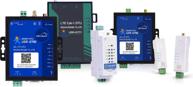
1. Product Overview1.1. Product Introduction
The 4G Cat 1 DTU is a series of LTE wireless data transmission terminals launched by Renhe IoT for various scenarios across multiple domains, featuring high speed, low latency, and ease of use. This series is divided into multiple models
1.2.
To meet diverse application needs, we offer a range of products, including the USR-G780s, USR-G771, USR-DR5X2, and USR-DR15X.Table 1 Product Selection
| Series | Product Positioning | Model | version |
| USR-G780s | Multi-functional positioning version 4G DTU | USR-G780s | supports GNSS, power-off alarm function, and EMC Level 4 |
| USR-G771 | is a cost-effective, full-network 4G DTU | USR-G771 | is the regular version with a protection level of EMC Level 3 |
| USR-G771-GL | is the isolated version with a protection level of EMC Level 4 and supports RS485 isolation | ||
| USR-DR5X2 | is a rail-mounted 4G Cat 1 DTU | USR-DR502 | is the DC version, operating from DC 9V~36V, with a protection level of EMC Level 3 |
| USR-DR512 | AC version, AC 120~240V, EMC Level 3 | ||
| USR-DR15X | Ultra-small size, lipstick-sized DTU | USR-DR154 | RS485 version, easy configuration and debugging via Bluetooth |
| USR-DR152 | RS232 version, easy configuration and debugging via Bluetooth | ||
| USR-DR150 | TTL level version, easy configuration and debugging via Bluetooth |
2. Product Features
2.1. MQTT Mode
Special Note: This feature is only supported in firmware versions V1.3.21 and above.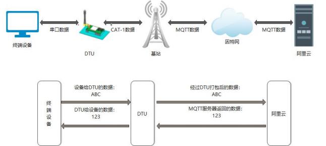 Figure 1. MQTT Mode
In this mode, the product functions as an MQTT Client, assisting users in quickly connecting to established private MQTT servers or public MQTT IoT cloud platforms. Users do not need to close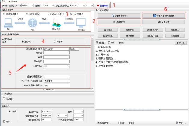 Figure 2. Schematic diagram of setting software MQTT mode
2.1.1.
This product utilizes a universal MQTT access method to connect to standard MQTT protocol IoT platforms, such as Baidu Cloud, Tencent Cloud, Huawei Cloud, AWS Cloud, etc., and also supports reconnection interval configuration2.1.1.1. MQTT connects to the server to achieve transparent data transmission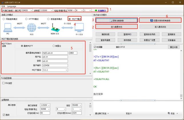 Figure 3. MQTT Basic Parameter Configuration(3) MQTT topic configuration:
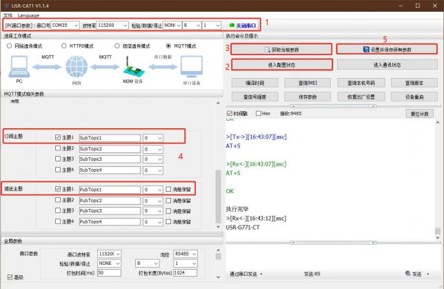 Figure 4. MQTT Topic ConfigurationSubscription Topic: The currently subscribed topic of DTU, which is the publishing topic of the MQTT server. In this example, configure topic 1 is checked, and the topic name and other settings remain at their default configurations
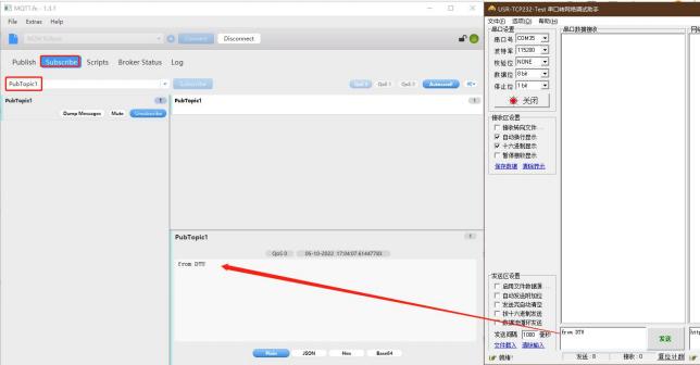 Figure 5. DTU Push Data TestIn the MQTT.fx software, enter the subscription topic of the DTU from the previous step as the publishing topic, and send data to the topic. You can see that the serial port debugging assistant can receive data from MQTT.fx.
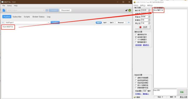 Figure 6. DTU Subscription Data Test
2.1.1.2. MQTT Connects to Server to Implement Data Distribution
Figure 6. DTU Subscription Data Test
2.1.1.2. MQTT Connects to Server to Implement Data Distribution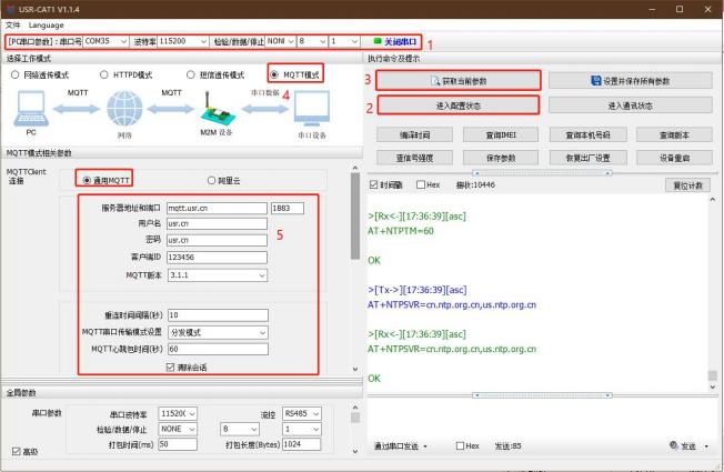 Figure 7. MQTT basic parameter settings(3) Configure theme
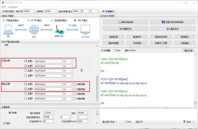 Figure 8. MQTT Topic Configuration(4) Save parameters
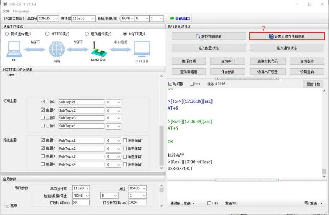 Figure 9. Setting and saving parameters2. Communication testing
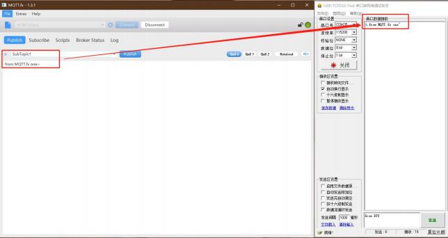 Figure 10. MQTT Subscription Data Test 1(1) Send data from MQTT.fx two~ to SubTopic2, then the serial port can receive 2, from MQTT.fx two~
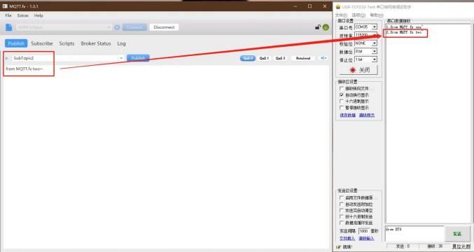 Figure 11. MQTT Subscription Data Test 2The MQTT.fx software connects to the same MQTT server, subscribes to the push topic configured by the DTU in the previous step, and reports data through the serial port in the format of "symbol,<payload> (symbol: topic sequence number)".
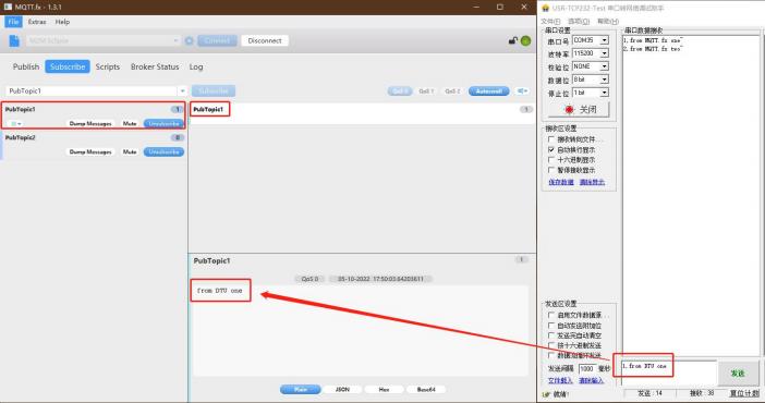 Figure 12. MQTT Push Data Test 1(2) Send 2 through the serial port, from DTU two, and the subscribed PubTopic2 in MQTT.fx will receive the data
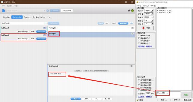 Figure 13. MQTT Push Data Test 2
2.1.2.
This product supports quick access to the Alibaba Cloud IoT platform, and supports device key authentication (triple) and X.509 certificate authentication for accessing Alibaba Cloud. The access options are very comprehensive, simple, and fast.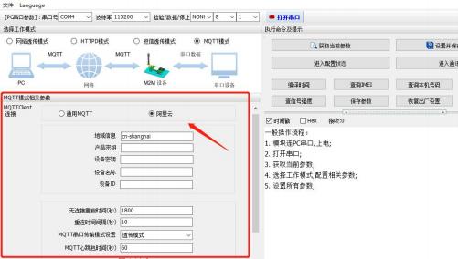 Figure 14. Schematic diagram of Alibaba Cloud access in MQTT mode
2.1.2.1Device secret key authentication for cloud accesshttps://iot.console.aliyun.com/(2) Click "Public Instance" -- "Device Management" -- "Product" -- "Create Product" in sequence to enter the new product creation interface (this example uses a public instance as an example, and in practical applications, you can choose the configuration according to your needs)
Figure 14. Schematic diagram of Alibaba Cloud access in MQTT mode
2.1.2.1Device secret key authentication for cloud accesshttps://iot.console.aliyun.com/(2) Click "Public Instance" -- "Device Management" -- "Product" -- "Create Product" in sequence to enter the new product creation interface (this example uses a public instance as an example, and in practical applications, you can choose the configuration according to your needs)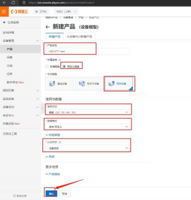 Figure 15 2. Add device
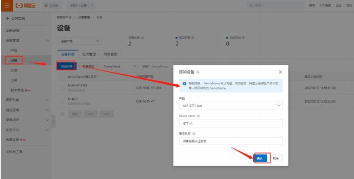 Figure 16. Add Device3. Device Configuration and Connection Information
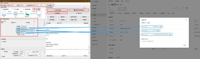 Figure 17. Schematic diagram of parameter settings4. Check the device for cloud connectivity
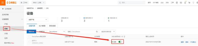 Figure 18
2.1.2.2X509 certificate authentication for cloud integrationhttps://iot.console.aliyun.com/(2) Click "Public Instance" -- "Device Management" -- "Product" -- "Create Product" in sequence to enter the new product creation interface (this example uses a public instance as an example, and in practical applications, configurations can be selected according to needs)
Figure 18
2.1.2.2X509 certificate authentication for cloud integrationhttps://iot.console.aliyun.com/(2) Click "Public Instance" -- "Device Management" -- "Product" -- "Create Product" in sequence to enter the new product creation interface (this example uses a public instance as an example, and in practical applications, configurations can be selected according to needs)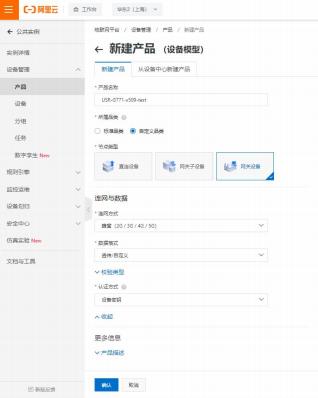 Figure 19 2. Add device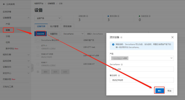
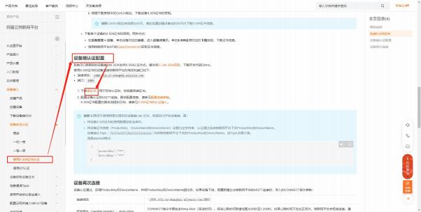 Figure 20 3. Certificate downloadAuthentication using X.509 certificate (aliyun.com)
Figure 21. Server Root Certificate Download(2) X.509 Device Certificate Download
Figure 20 3. Certificate downloadAuthentication using X.509 certificate (aliyun.com)
Figure 21. Server Root Certificate Download(2) X.509 Device Certificate Download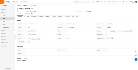 Figure 22. Device Certificate Download
Note: Restrictions on Alibaba Cloud X.509 Connection Authentication:
Figure 22. Device Certificate Download
Note: Restrictions on Alibaba Cloud X.509 Connection Authentication:
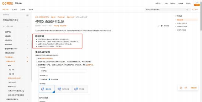 Figure 23. Limitation description4. Equipment configuration1.3.2.3 Certificate downloadServer root certificate in1.3.2.3 Certificate downloadX.509 certificate of the device in
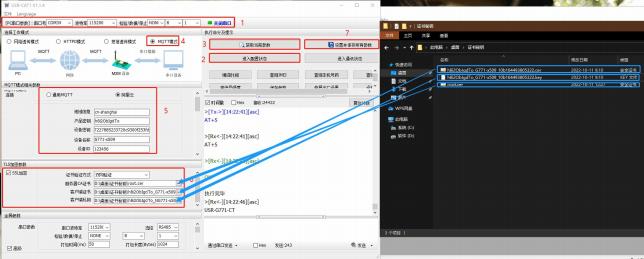 Figure 24. Schematic diagram of parameter configuration5. Check device cloud connection
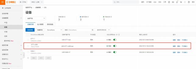 Figure 25 2.1.2.3. Subscription and publication
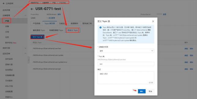 Figure 26 2. Equipment configuration
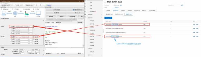 Figure 27. Theme parameter configuration3. Viewing data transparent transmission
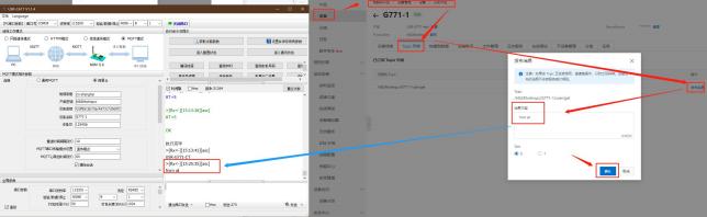 Figure 28. Transparent data communication test-1Device reporting data:
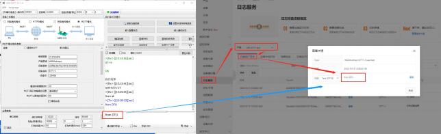 Figure 29. Transparent Data Communication Test-2(2) Distribution mode
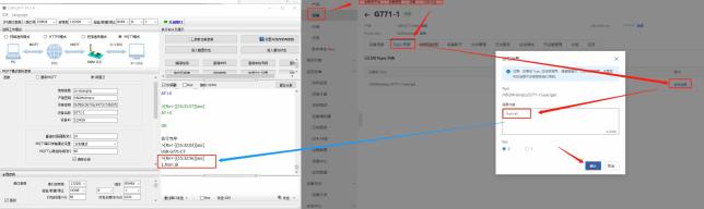 Figure 30. Distributed Data Communication Test-1Device reporting data:
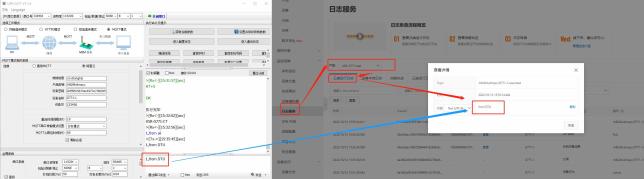 Figure 31. Distributed Data Communication Test-2
2.1.3. SSL/TLS Encryption
Special Note: This feature is only supported in firmware versions V1.3.21 and aboveThe device supports SSL/TLS encryption when operating in MQTT mode and HTTPD Client mode. If the target server has SSL certificate verification enabled, SSL encryption parameters need to be configuredTable 2 Authentication Methods
| verification mode | Explanation | Usage recommendations |
| No verification certificate | Only implement data layer transmission decryption, without verifying the identity of the other party during the handshake process | No encryption scenario |
| Verifying server certificate | During the handshake, the client verifies the server certificate, requiring the client to pre-configure the server's root certificate | Verifying device validity scenario |
| Mutual verification | That is, the client and server mutually verify each other's identity, requiring the pre-configuration of the server's root certificate and the client certificate | Strong security scenario for data transmission |
2.1.4.
(1) Operating mode:
2.2.
2.2.1.
With firmware version V2.3.03.000000.0000 and above of the 4G Cat1 series, users can add and configure gateway products by scanning a QR code with their mobile phones, completely eliminating the need for serial cables and host computers. Just scan the QR code with your phone,https://www.usr.cn/Download/1304.html
2.2.2. Product Customization
For firmware versions V2.3.03.000000.0000 and above of the 4G Cat1 series, if you want to use the gateway product without configuration, you can also customize the parameters through the Rongren Cloud Customization Center. One device can also be customized, offering exclusive personalization. Currently, the customization center supports gateway parameter customization, such as gateway working mode, gateway serial port parameters, socket server address and port, heartbeat packets, registration packets, and other gateway-related parametershttps://www.usr.cn/Download/1305.html
2.2.3.
1) Register/log in with a personnel passcloud.usr.cn) -> "Console" in the top right corner -> Register/Log in to a Passport Account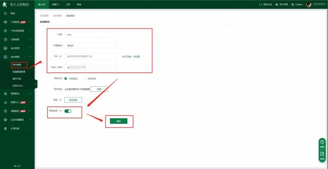 Figure 32. Example of adding a device
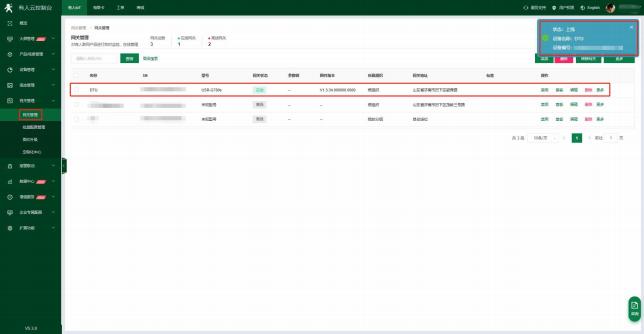 Figure 33. Online prompt after successful addition
2.2.4.
① Operation entry for upgrading firmware individually: Somebody IoT -> Gateway Management -> Gateway Management -> "More" on the far right -> Firmware Upgrade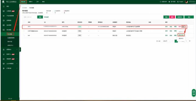 Figure 34. Single Device Firmware Upgrade② Multiple entry points for firmware upgrade operations: Smart Home Hub -> Gateway Management -> Firmware Upgradehttp://cloud.usr.cn/document/monitor/ota.html
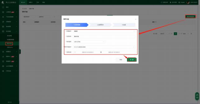 Figure 35. Batch Firmware Upgrade
2.2.5. Network Monitoring and Alarming
Some cloud platforms provide alarm push functionality. After setting alarm condition rules in the cloud, when a device generates an alarm, it can be pushed to the relevant personnel through one or multiple methods such as WeChat, SMS, and email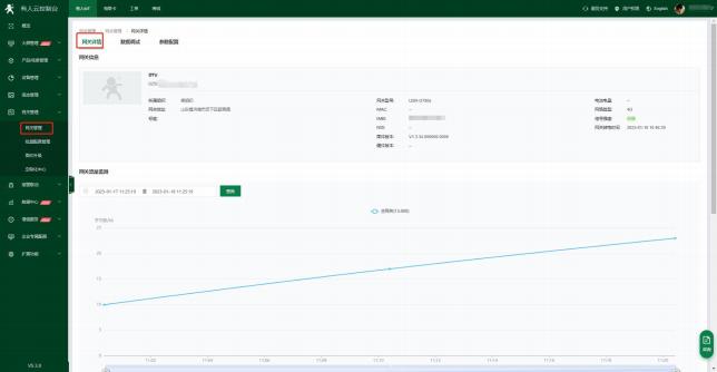 Figure 36. Equipment OverviewAlarm push notification:
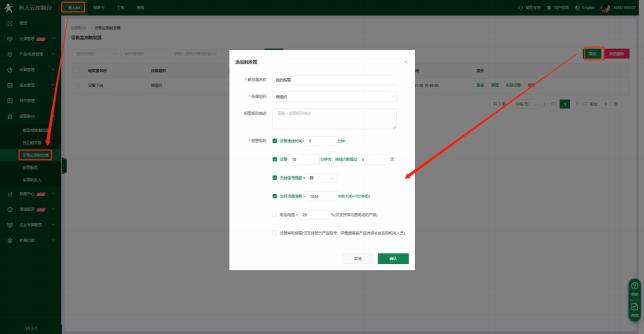 Figure 37. Device Monitoring Trigger② Alarm push rule configuration: IoT device -> Alarm linkage -> Add alarm on the alarm configuration interface, and select the corresponding device and push rule.
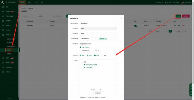 Figure 38
2.2.6.
Support online device statistics, device model distribution, device tag statistics, alarm statistics, firmware version distribution, and new device addition.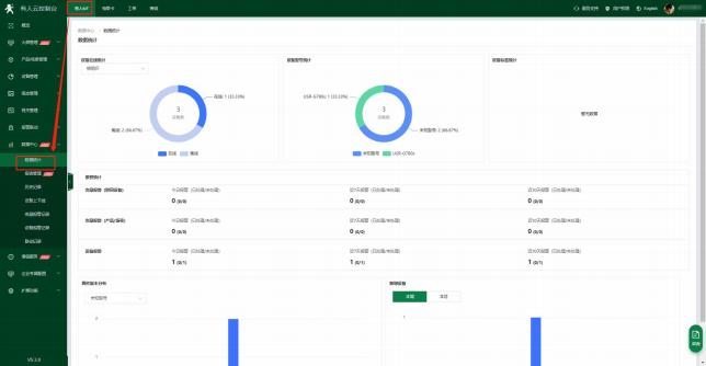 Figure 39
2.2.7. Power-off Alarm
Some products in this series support power-off alarm for devices through the Youren Cloud. It monitors the online status of the DTU through the Youren Cloud platform, and if there is an offline situation caused by device power-off, it willNote: The model USR-G780s supports this function.
2.2.7.1Power failure alarm prompt
During normal device usage, if a power supply disconnection is detected, an automatic power outage alarm message will be sent to Youren Cloud, which will prompt with a pop-up window.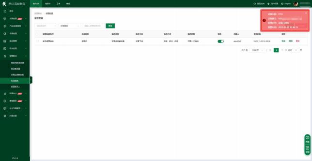 Figure 40. Page prompt under power failure alarm
2.2.7.2Add alarm trigger
Add entry: someone IoT -> alarm linkage -> device monitoring trigger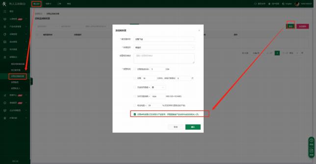 Figure 41. Adding a trigger1) Associated devices
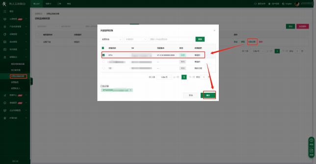 Figure 42 2) Alarm push rule settings
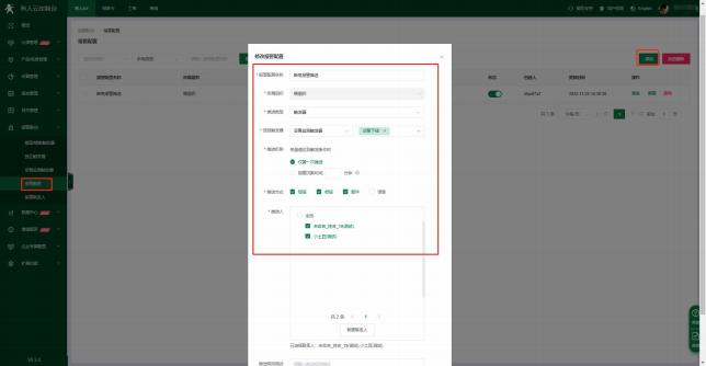 Figure 43. Add Alarm Push
2.2.7.3. Power-off Alarm Push
Power off the device, and after the device goes offline, the cloud platform will push alarm information according to the set push method, as shown below: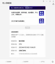 Figure 44. WeChat Official Account Push
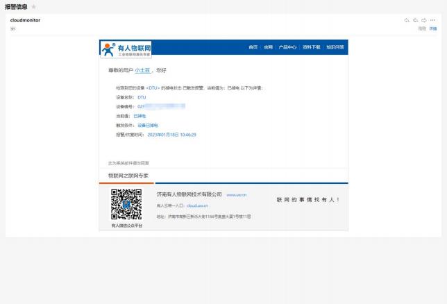 Figure 45. Email Alarm Push
2.3. Network Transparent Transmission Mode
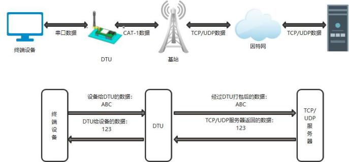 Figure 46. Network Transparent Transmission Mode
In this mode, the user's serial device can send data to the specified server through the DTU, and the DTU can also receive data from the server and forward the information to the serial device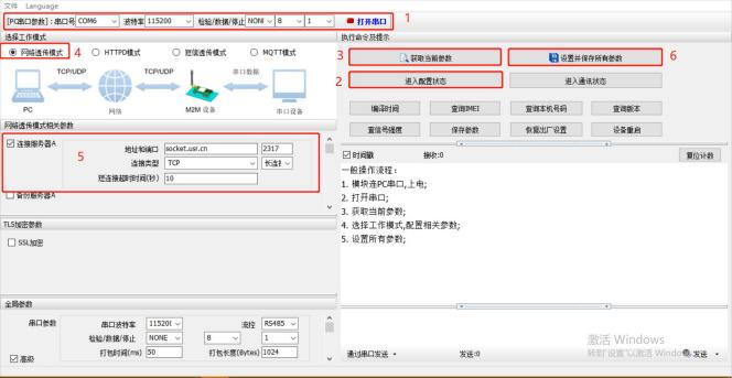 Figure 47. Schematic diagram of software setup
2.3.1.
The registration package can serve as an authorization code for DTU to access server functions, and also as a data packet header to facilitate the server's identification of data sources. Therefore, when using this product, it can be used on the networkRegistration package sending method: Depending on the different functions of the registration package, different sending methods are chosen. There are three sending methods for the registration package of this product:Registration package content:Based on the requirements, you can choose ICCID code, IMEI code, SN code, CLOUD, or custom data as the registration package data. Customers using Youren Cloud can select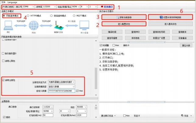 Figure 48. Schematic diagram of software setup
2.3.2.
In the network transparent transmission mode, users can choose to enable the DTU to send heartbeat packets to fulfill specific requirements.Heartbeat packet transmission method:The heartbeat packet can be sent to the network side or the serial port device side.Content of heartbeat packet:Based on requirements, you can choose ICCID, IMEI, SN, LBS, or custom data as the heartbeat packet data.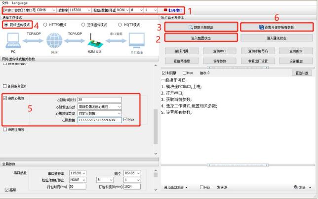 Figure 49. Schematic diagram of setting softwareIn addition to the above settings, you also need to make settings for TCP/UDP connections, such as the settings for Socket A, Socket B, Socket C, or Socket D. After completing the settings,www.usr.cn.
2.3.3.
When DTU operates in network transparent transmission mode, each socket can be individually configured with a backup server. If the primary server is unreachable, DTU will attempt to connect to the backup server,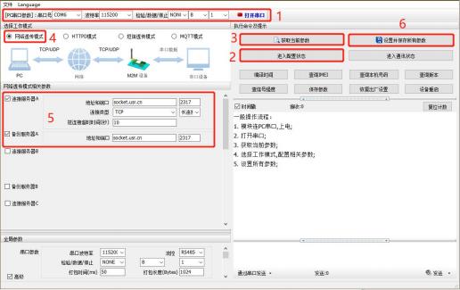 Figure 50. Schematic diagram of software setup
2.4.
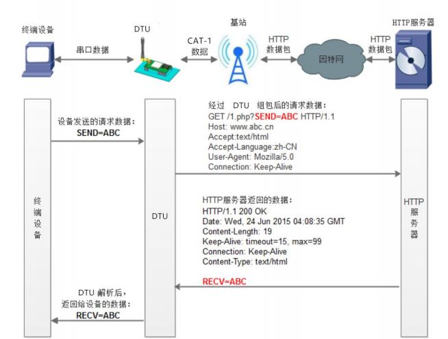 Figure 51. HTTPD Client Mode
In this mode, the user's terminal device can send request data to the specified HTTP server through this module, and then the module receives data from the HTTP server and processes itSpecial note: Devices with firmware version V1.3.21 or above support SSL/TLS encryption when operating in HTTPD Client mode.Set software settings: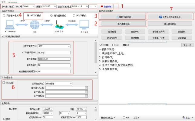 Figure 52. Schematic diagram of software setup
2.5.
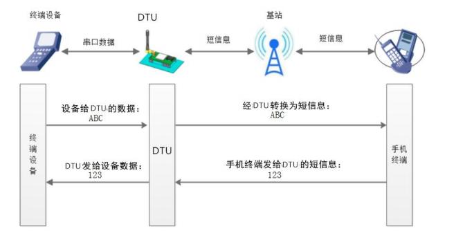 Figure 53. Diagram of SMS transparent transmission mode
In this mode, the user's serial port device can send text messages to a specified mobile phone, and can also receive text messages from any mobile phone. The user can decide whether to limit the sending or receiving of messages through settings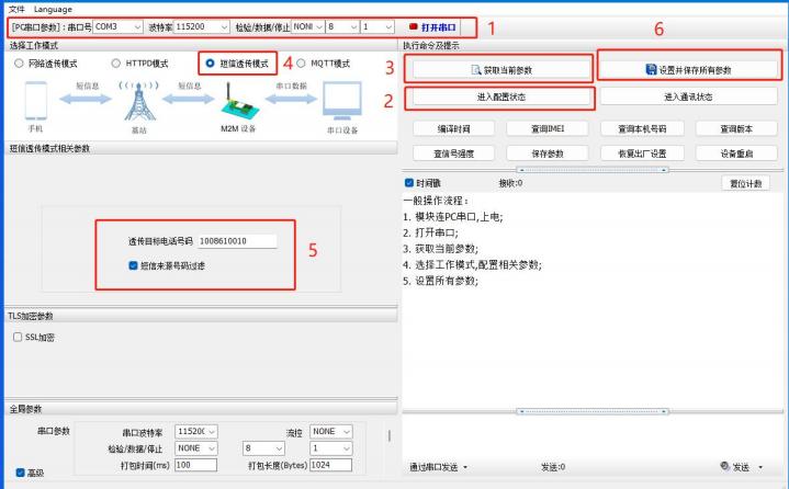 Figure 54. Schematic diagram of setting softwareNote: When non-target phone number filtering is enabled, non-target phone numbers can still query the set parameters. In SMS transparent transmission mode, SMS AT commands still take effect.
2.6.
Note: The USR-G780s features GNSS positioning capability, which can assist users in quickly accessing public clouds, private clouds, and Qianxun Cloud.2.6.1. 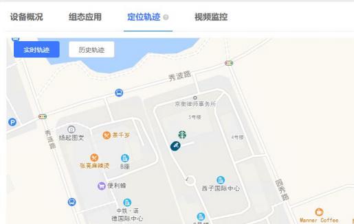 Figure 55. Location trajectory map of someone's cloud
2.6.2.
Connecting to a private cloud allows for the reporting of raw positioning data, which users can process using their own servers. Alternatively, they can report processed data that adheres to a unique data protocol specific to their needsBased on independent channels:Supports TCP connections and allows for the setting of custom servers;$GNRMC,025322.000,A,3107.53626,N,12121.50788,E,0.00,0.00,230821,,,A*7CGGA Type$GNGGA,025519.000,3107.53869,N,12121.51101,E,1,24,0.7,43.5,M,0.0,M,,*4AModbus Positioning Type01 46 00 00 00 11 22 00 19 00 01 BF 56 F9 D2 56 F0 40 5E 0A B3 01 9B 20 2E 40 3F 01 CC 00 00 18 71 01 A7
E9 23 61 23 0E 78 99 C9Setting Software Configuration Method as follows: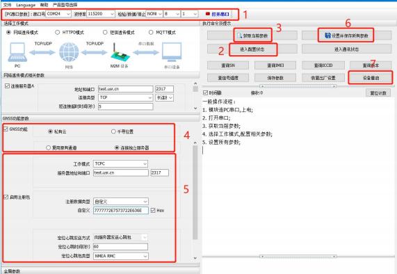 Figure 56. Schematic Diagram of Setting Software
Reuse of Existing Channel:. This mode can only operate in "Network Transparent Mode", and once the reuse function is enabled, the positioning heartbeat packet will replace the original regular heartbeat packet (regardless of whether it is enabled or not). The positioning heartbeat packet in this case is the same as when connecting to an independent channel, both supporting switching between three types. The only difference is that in this mode, the positioning heartbeat packet can be sent to the serial port, while the positioning data under the independent channel can only be sent to the network side.
Figure 56. Schematic Diagram of Setting Software
Reuse of Existing Channel:. This mode can only operate in "Network Transparent Mode", and once the reuse function is enabled, the positioning heartbeat packet will replace the original regular heartbeat packet (regardless of whether it is enabled or not). The positioning heartbeat packet in this case is the same as when connecting to an independent channel, both supporting switching between three types. The only difference is that in this mode, the positioning heartbeat packet can be sent to the serial port, while the positioning data under the independent channel can only be sent to the network side.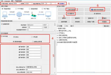 Figure 57. Schematic diagram of software setup
2.6.3.
Qianxun Cloud is similar to Youren Cloud in that both can display real-time locations and path records on the platform. However, the standard JT808 protocol is used for interfacing with the Qianxun platform. If the customer's server supportshttps://ares.my.qxwz.com
 In "Entity Management", you can add your own devices and modify related parameters. However, once the phone number used by each device is set, it cannot be modified (it can only be deleted and re-added), and it cannot be reused because the number is already bound to the device and cannot be bound to other devices again. After successfully creating a new device, reset the authentication code to prevent the device from failing to log in for the first time.
 Next, we will configure the module-related parameters. The TCP server is connected to Qianxun Cloud by default, and no changes are necessary unless there are special requirements;
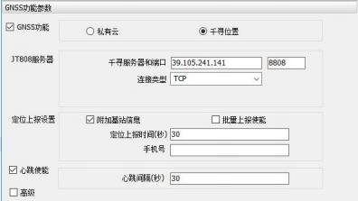 In the positioning reporting settings, "Attach Base Station Information" enables the inclusion of base station information when reporting positioning data. This is a unique additional message in Qianxun, and can be unchecked when using the standard JT808 protocol. "Batch Reporting" refers to the function of saving valid positioning data when network conditions are poor, and then reporting it collectively once the network status is restored. The reporting follows the JT808 protocol
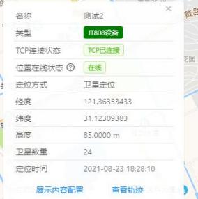
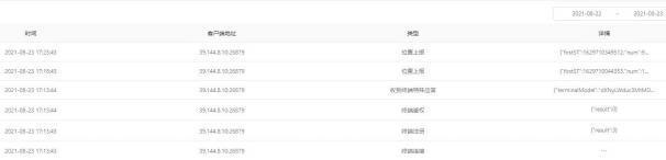 Switch to the "Map Monitoring" interface, where you can see that the device has gone online and the current location of the device is displayed on the interface. Click on the green dot corresponding to the device to view the specific information
 Set software settings:
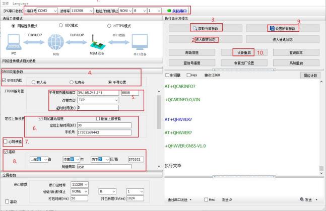 Figure 58. Schematic diagram of software setup
2.7.
Note: DR15X Standard Edition supports WeChat Mini Program configuration function.Users can directly scan the QR code on the front of the product via WeChat on their mobile phones, and quickly configure parameters and debug devices through the WeChat mini program, making the configuration of DTU hassle-free.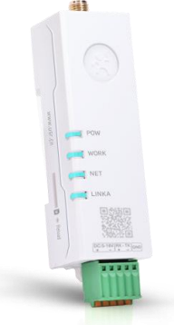 Click "Re-enter Mini Program".
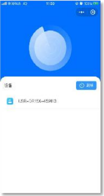 Figure 59. Example diagram of SMS AT command2) The WeChat mini-program "Lianboshi Configuration Tool" automatically scans the DTU devices near the phone, each of which has a unique Bluetooth name, and this Bluetooth name is "USR-DR15X-"The initial value of the connection password is "usr_cn"The password can be reset after entering the WeChat mini program (with a length of 1-10 characters). After the first successful connection, the device can automatically record the connection verification
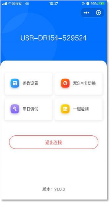 Figure 41 Schematic diagram of the main interface of WeChat Mini Program5) The main interface of the WeChat mini-program "Lianboshi Configuration Tool" includes the following functions:
2.7.2.
1) Enter the main interface of the WeChat mini program "Lianboshi Configuration Tool", click the "Parameter Settings" option, and enter the parameter configuration interface. The interface is shown below. The mini program will automatically obtain the current DTU settings and display them on the WeChat mini program interface, allowing users to intuitively view the configured values of the device. Users can modify the parameter values and click the "Set" button to proceed with the settingsSpecial note: The MQTT mode feature is only supported in firmware versions V1.3.21 and above.
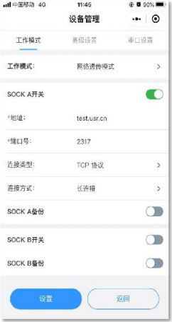
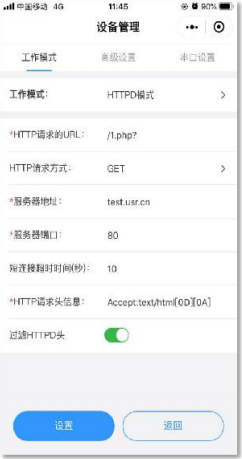 Figure 42 Schematic diagram of network transparent transmission mode and HTTPD mode configuration
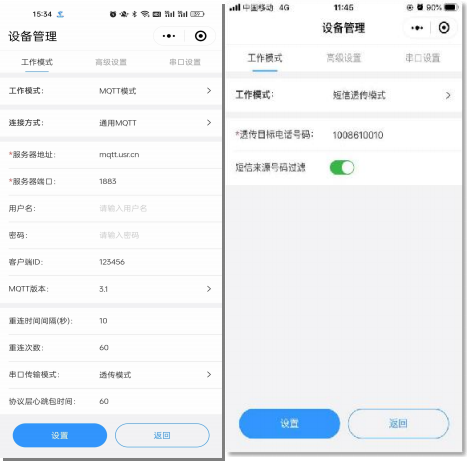 Figure 43 Schematic diagram of MQTT and SMS transparent transmission mode2) In addition to setting the working mode of the DTU, you can also configure its startup information, security password, NTP service, and more, enhancing user experience. Advanced settings
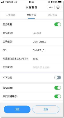 Figure 44 Schematic diagram of advanced settings interface3) Parameter settings also include configuring the serial port of the DTU. After setting all the parameters of the serial port, the DTU will automatically save the settings and restart to take effect. The serial port settings are shown in the following figure:
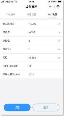 Figure 45 Schematic diagram of serial port settings
2.7.3. Dual SIM card switching settings
1) This product supports dual-card single-standby functionality, and our company has designed three SIM card usage modes for users to choose from. The SIM card switching settings can also be configured in the WeChat mini program.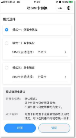 Figure 46 Schematic diagram of dual SIM card switching interface
2.7.4.
1) To facilitate user debugging of their device terminals or the serial port section of the DTU, WeChat Mini Program has added a serial port debugging interface.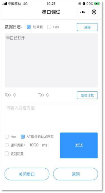 Figure 47 Schematic diagram of serial port debugging interface
2.7.5.
1) The one-click detection function is added to detect the operating status of the device. After entering the one-click detection interface, click the detection button, and the WeChat mini program will automatically communicate with the DTU via Bluetooth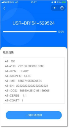 Figure 48 Schematic diagram of one-click detection interface
2.8.
2.8.1. SIM Card Mode
This product features dual-SIM single-standby functionality, with a built-in SIM card. It comes with free data allowance of 100MB per month, which can be renewed by logging into the SIM card management platform. An external SIM card slot is reserved for convenienceTable 3 SIM card data usage
| Model | traffic |
| USR-G780s | Comes with 8 years of free data allowance, with 100M per month |
| USR-G771 | Comes with 8 years of free data allowance, with 100M per month |
| USR-DR5X2 | Comes with 8 years of free data allowance, with 100M per month |
| USR-DR15X | Free 3-month data allowance, 100M/month, with the option to renew and change plans through the SIM card platform. |
To cater to different user needs, our company has designed three SIM card usage modes for customers to choose from. The SIM card usage modes are as follows:Table 4 SIM Card Usage Modes
| SIM Usage Mode | Description | Usage Recommendation |
| External Card Preferred | When plugged in, the external card will be used for networking operations, regardless of whether the external card can connect to the internet normally; | Default setting, recommended. |
| Dual-SIM backup | When both external and internal SIM card network plans are in use, in case of network anomalies or SIM card arrears | When high network reliability is required |
| Single SIM Lock | Lock a SIM card for use, without SIM card detection and automatic switching; | Users use as needed |
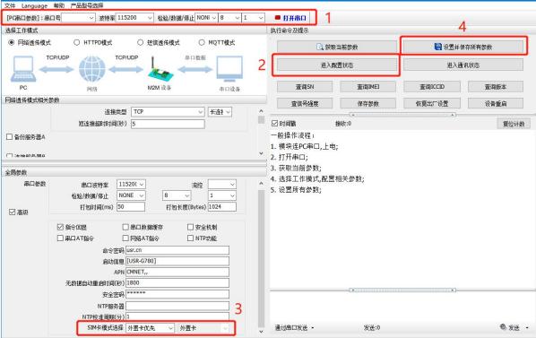 Figure 60. Schematic diagram of setting software
2.8.2.
DTU has a security mechanism. When the security mechanism is selected and the configuration state is entered, the user needs to enter a correct password login command before proceeding with subsequent operations. If the password is correct, the device is logged in, and sending another login command is an operation to modify the login password. If the login password is incorrect, it will return "+CME ERROR:73". Other non-login commands will prompt "please"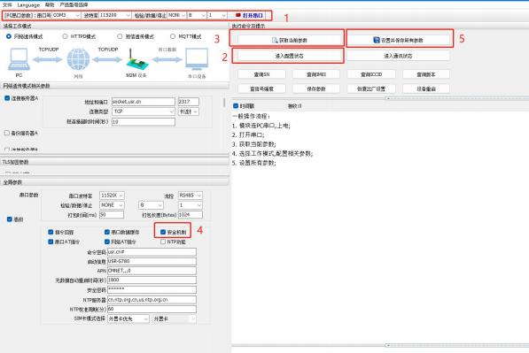 Figure 61. Schematic diagram of software setup
2.8.3.
This product supports time synchronization using NTP servers. This feature is disabled by default, and up to 4 NTP servers can be set.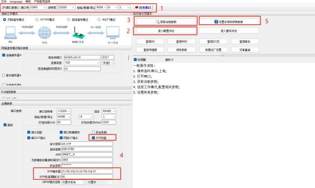 Figure 62. Schematic diagram of setting software
2.8.4.
This product supports the FTP upgrade protocol. User devices can request files from the FTP server using a special protocol through the serial port, and can divide the server's files into small packets for transmissionhttps://www.usr.cn/Download/696.html.
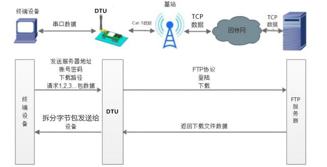 Figure 63. Schematic diagram of FTP upgrade protocol
2.8.5. Base station positioning
This product supports base station positioning function, which can obtain the approximate location of the device through the operator's network, with a positioning accuracy generally around 100 meters. Base station positioning information is obtained through AT instructions
2.8.6.
This product supports two upgrade methods: remote FOTA upgrade and USB upgrade. For remote FOTA upgrade, it is necessary to contact the manufacturer's technical support, provide the IMEI and the current version number of the device, and alsohttp://im.usr.cn;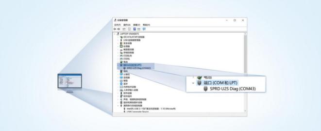 Figure 64. Diagram for identifying download ports5) Upgrade Tool: If you need an upgrade tool, you can contact the manufacturer's corresponding sales department or submit a work order to obtain it. After obtaining it, locate the download tool "UpgradeDownload.exe" in the corresponding path (UPGRADEDOWNLOADBin) and open it.
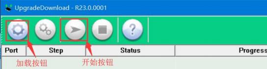 Figure 65. Diagram of downloading software7) Multiple device downloads: After one download is completed, simply replace the device. Once all devices have finished downloading, click the stop button to halt the programming process, and then close the software.
 Figure 66. Schematic diagram of upgrade completion
2.8.7. No data/connection restart mechanism
The device introduces an exception handling mechanism for no data restart (TCP/UDP/HTTP transparent transmission mode) and no connection restart (MQTT transparent transmission). This mechanismis enabled by defaultwith a parameter of 1800s. That is, if the device does not receive user data (from the server) or MQTT connection within 30 minutes, it will automatically restart. This function can be configured and parameterized through the AT command: AT+RSTIM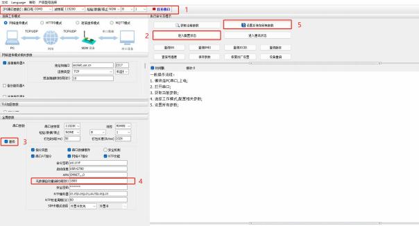 Figure 67. Automatic restart configuration without data
2.8.8.
This product supports the Socket Distribution Protocol. In the DTU application process, the device only has one communication serial port. Therefore, in multi-Socket applications, the data received by the serial port will be sent simultaneously to multiple Sockets. However, many times, the application of multiple Sockets is to send different data to different servers. To solve this problem, we have added the Socket Distribution Protocol, which distributes data to the corresponding servers according to the protocol. At the same time, the data replied by each server will also be sent to the serial port after adding the Socket protocol, so that the serial port device can judge the data according to the protocol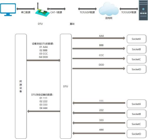 Figure 68. Schematic diagram of socket dispatching protocolThe specific protocol for the socket can be downloaded from the official website. https://www.usr.cn/Download/697.htmlThe length of the socket packet must still comply with the requirements of the packaging mechanism, that is, the total length obtained by adding the data length and the socket protocol length must be less than the packaging length in order to execute correctly. If it exceeds the packaging length3. Serial Port SettingsParameter configuration primarily refers to the process of setting and saving the parameters of the DTU through a fixed method. Currently, multiple configuration methods are supported, allowing customers to flexibly choose according to their needs.Configuration Approach:Parameters can be set through AT commands or configuration software. For customers using a PC to operate the device, it is recommended to use configuration software for convenience and efficiency. For those using an MCU to configureAT command setting method:AT command settings are categorized into configuration mode, serial port AT, network AT, and SMS AT based on different requirements.Send specific characters at specific timing to enter the configuration stateAfterwards, send AT commands to perform operations. After completion, restart the device or exit the configuration mode before normal data transmission can be carried out. Data communication is not possible in configuration mode; only command operations can be executed.noteThe formats for using serial port AT, network AT, and SMS AT are the same, all following the format of "command word + instruction", for example, "usr.cn#AT+VER". "usr.cn#" is the default command word, and "AT+VER" is the instruction.
3.1.
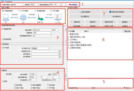 Figure 69. Schematic diagram of software setupExplanation
:
3.2.
Table 5 Basic parameters of serial port| project | parameter |
| Baud rate | 1200~230400 |
| data bit | 8 |
| stop bit | 1,2 |
| check digit | NONE (no check digit) |
| Flow control | NONE |
3.3.
1) Time-triggered mode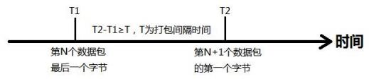 Figure 70. Time-triggered mode2) Length trigger mode
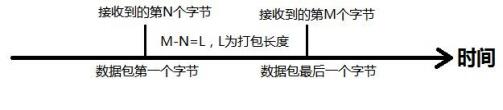 Figure 71. Length-triggered mode
3.4.
The DTU parameters can be configured and queried through AT commands. For specific AT commands, please refer to the "4G Cat1 DTU Standard AT Command Set"


Leave a Reply