
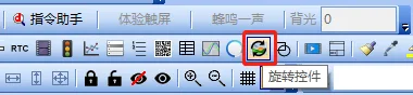
What is a rotary control?
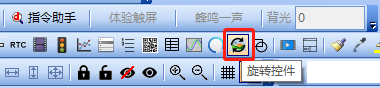
As shown in the above figure, it is only suitable for M/IoT type. The rotary control is in the format of a custom pointer, which rotates by setting a coordinate for the rotary control, and then displays in conjunction with the dial (background image)
Rotating controls, IoT type, M series, H series, X series
Routine download link: "<"Serial port screen dial application>(Click to jump)
16.1 Introduction to Rotation Control Attributes
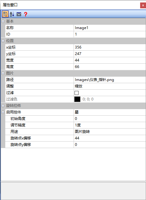
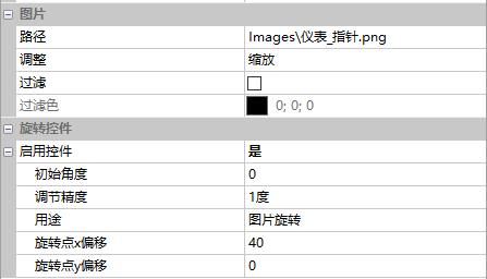
Users can insert images of any size through the rotation control, set the corresponding rotation center, and have the image rotate around the corresponding rotation center, thus achieving the function of a dial. The property window of the rotation control is shown below
path
file path of the material image
adjustment
"zoom" or "crop"
- Zoom in/out of the entire image display
- Crop and display the image, crop by adjusting the size of the rotation control
Filter
"Check" or "Cancel". The [Filter Color] will only take effect after checking
Filter Color
After selecting the filter option, set: choose the color to be filtered
Enable control
Select "Yes" or "No"; select "Yes"
Initial angle
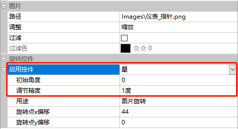
The initial rotation angle of the image, as shown below:
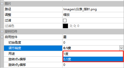
Adjustment precision
"1 degree" or "0.1 degree", as shown below:
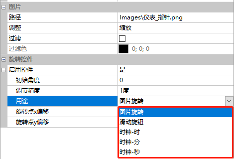
Usage
The purposes of the rotation control include "Image Rotation", "Slider Knob", "Clock-Hour", "Clock-Minute", and "Clock-Second", as shown below:
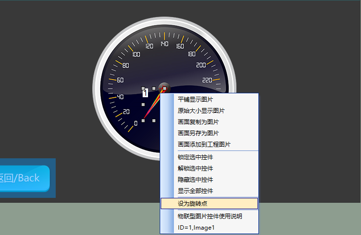
Rotation Point x Offset/Rotation Point y Offset
Coordinates of the rotation center. Users can place the mouse pointer on the corresponding coordinates, then right-click and select "Set as Rotation Point", as shown below
Limit Angle
This is effective in Slider Knob mode. Select "Yes" or "No"
Maximum Angle
This is effective in Slider Knob mode. When the Limit Angle is enabled, the range of "Maximum Angle" is 0~360
Notification Method
This is effective in Slider Knob mode. Select "When Released" or "When Sliding"
16.2 Application of Rotation Control
On the [Rotating Controls] screen, by inserting the "hand" image material and setting the corresponding rotation center, the image can be rotated around the rotation center, thus realizing the application of the dial
Screen Configuration
Import the corresponding artwork image for the "Background Image" in the "Instrument Controls" screen as shown below
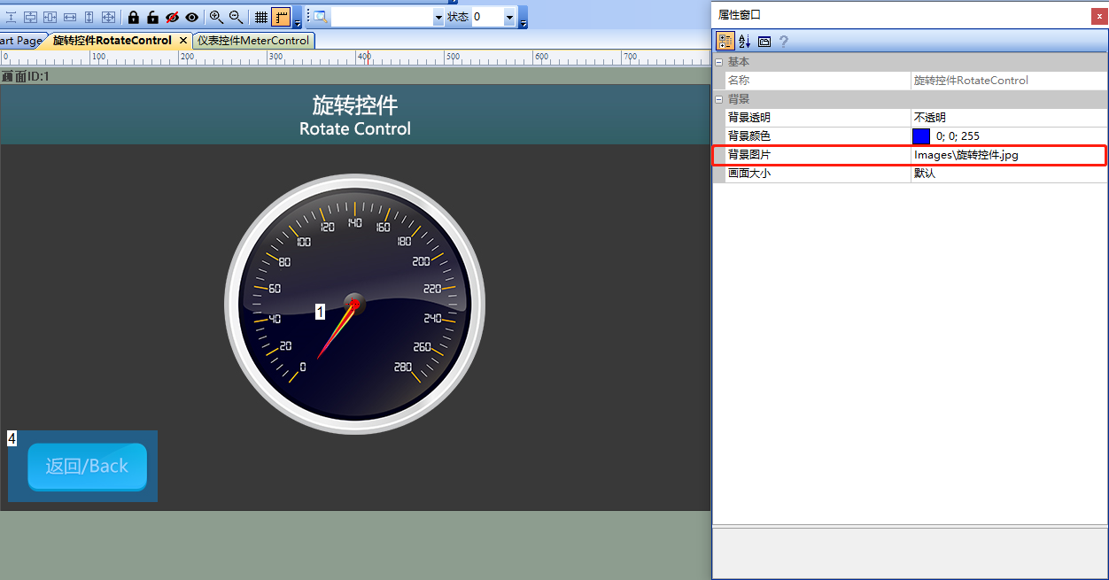
Add a Rotation Control (Control ID: 1) to the screen. At this point, a pop-up box will load the material image of the rotation control, as shown below
Property Configuration
In the property window of the instrument control, set the rotation point X/Y offset. Select the rotation control, right-click, and a selection box will pop up. Select "Set Rotation Point", as shown below
Run Preview
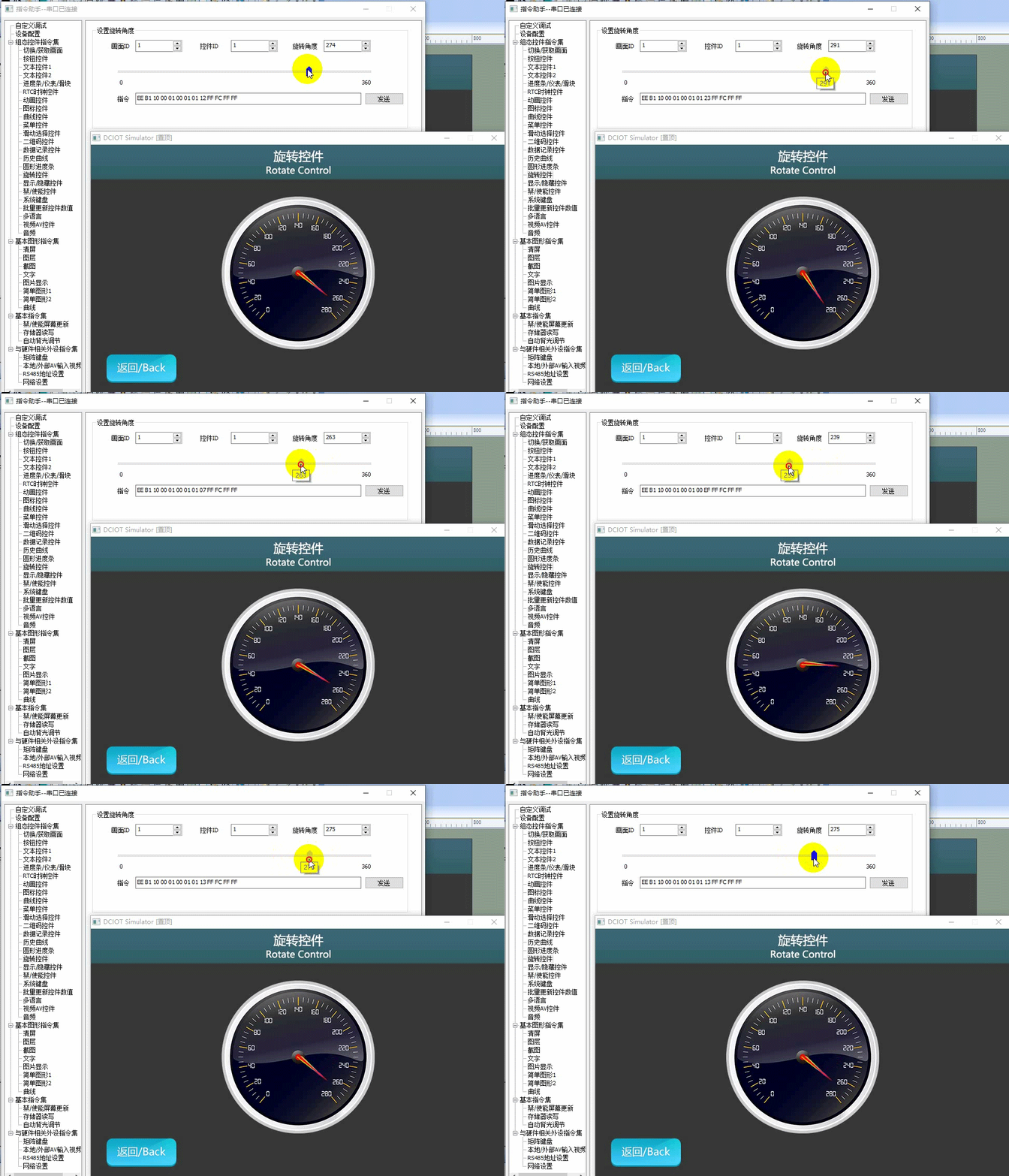
Run the virtual screen, and establish a connection between the VisualTFT software and the virtual screen using a "Virtual Serial Port". Open the "Command Assistant", select "Rotation Control" on the left navigation bar, and set the "Set Rotation Angle" command parameter. As in the example routine, control the rotation control (Control ID: 1) in the screen (Screen ID: 1), fill in the "Value" as "200", and click "Send"; alternatively, drag the slider in the Command Assistant to set the instrument control value. The running effect is shown below
Single-chip Program
The user's single-chip program for controlling the rotation control update refers to the function declaration in the him.dever.h file and the definition in the him.dever.c file in the development package Keil program. The function declaration in the Keil program is shown below
/**********************************************************************
** Function name: void Set_RotateValue(uint16 screen_id,
**                                     uint16 control_id,
**                                     uint16 value)
** Descriptions    : 设置旋转控件值
** input parameters: screen_id: 画面ID
**                  control_id: 控件ID
**                       value: 需要设置的控件值
** output parameters : 无
** Returned value    : 无
*********************************************************************/
{
    ……
    RotateValue (1,1,200);//设置画面1、控件1旋转控件值为200
    ……
}

Leave a Reply