
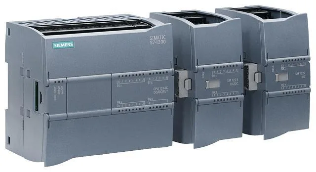
Before establishing communication, we must meet the following hardware and software requirements:
●1. A computer equipped with TIA V16 software;
●2. Two Siemens series PLCs, which must support the use of TIA Portal V16 version;
●3. A DP9-pin male connector (for use with 1200 port), a DP15-pin male connector (for use with 1500 port), and a two-core shielded cable (specification: 0.5 square);
●4. The communication module models and specifications used in today's experiment are as follows:
CM1241RS422/485, order number: 6ES7 241-1CH320XB0;
CMPtP RS422/485HF, order number: 6ES7 541-1AB00-0AB0;
The following images show the communication modules and DP connectors required for today's demonstration;
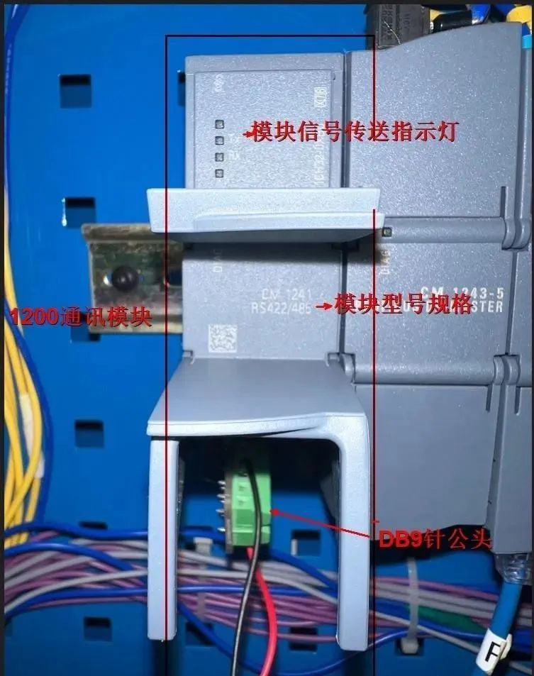
1200 port communication module
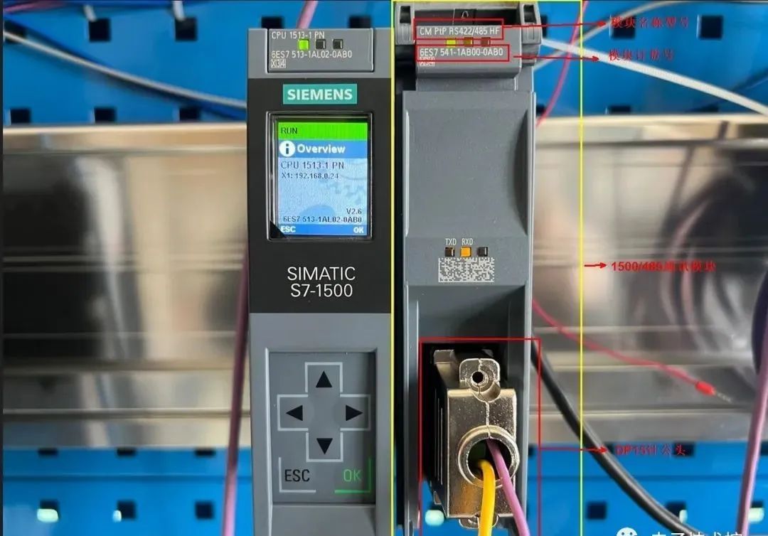
1500 port communication module
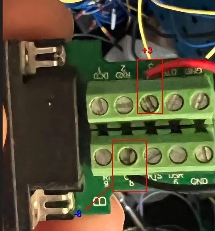
1200 port DP9-pin male connector
1500 terminal DB15 male connector
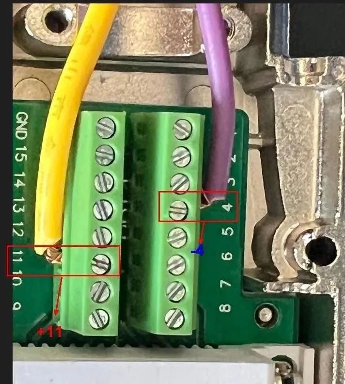
1200 and 1500 modbus connection:
1200 PLC terminal 1500 PLC terminal
3+ 11+
8- 4-
Configure the master station (1200 terminal):
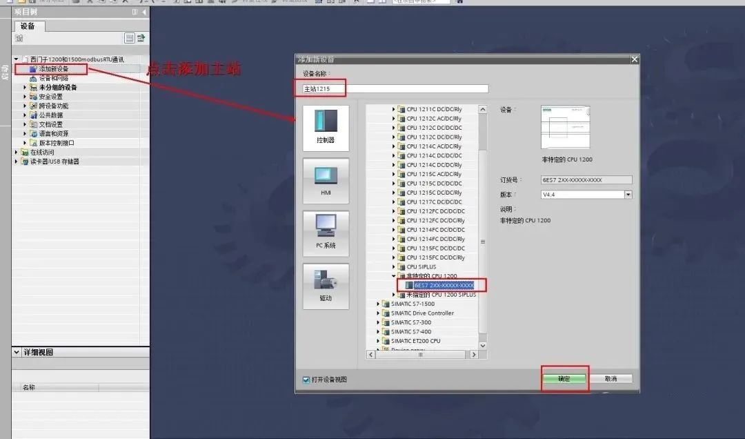
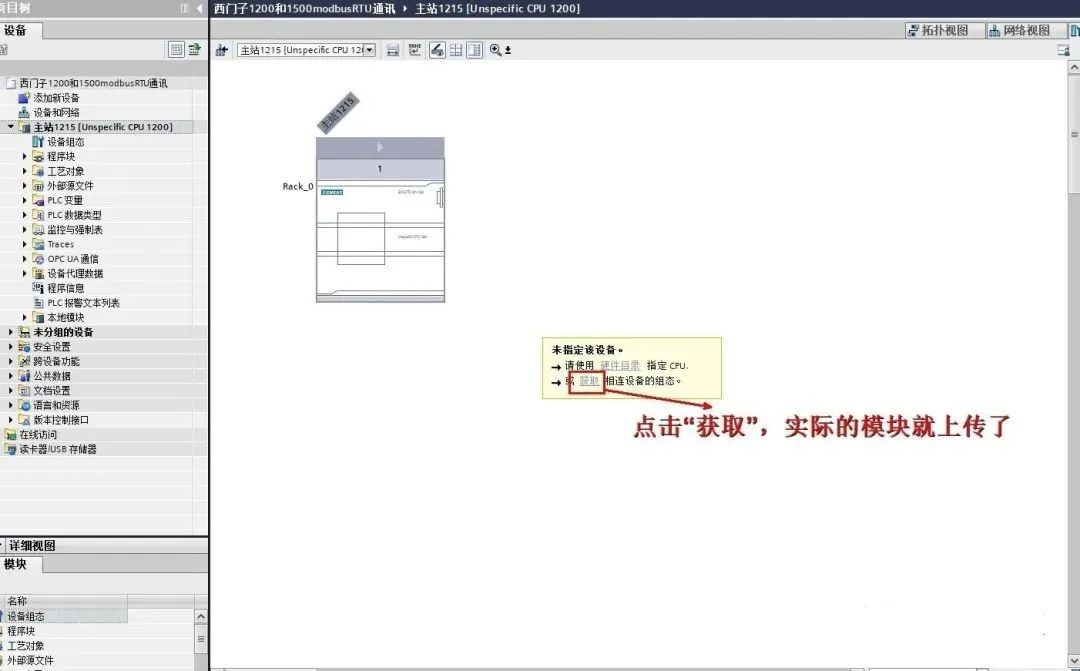
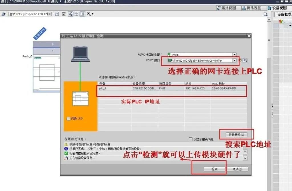
1. Create a project and add a CPU and RS485 module as shown below:
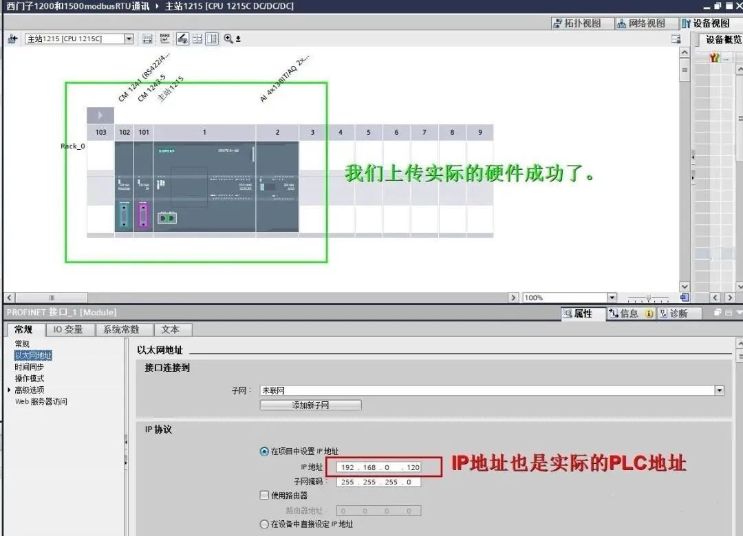
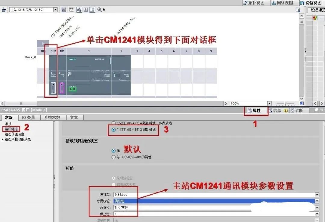
2. After adding the hardware, set the parameters of the CM1241-R485 module here:
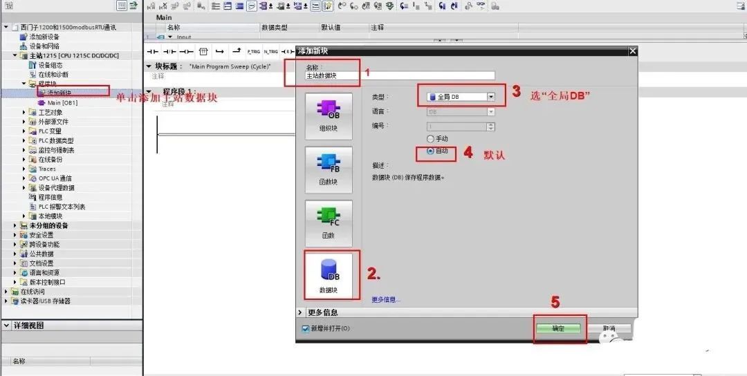
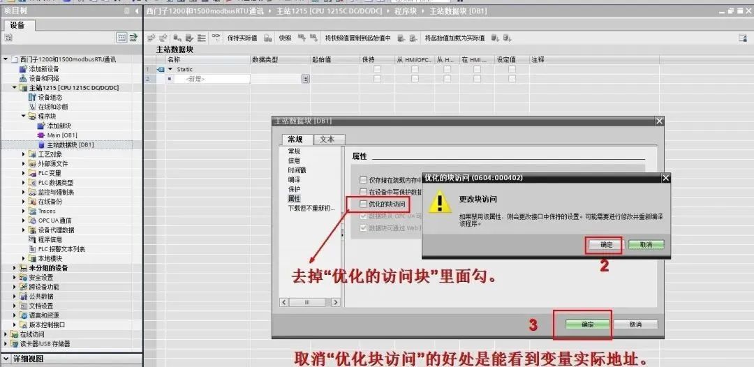
3. Create a DB block for the 1200 PLC terminal (master station) to store data:
Modify the DB block to "optimize for access".
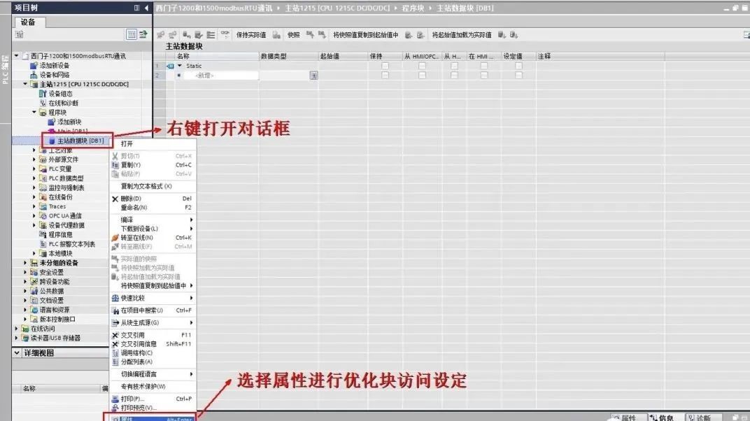
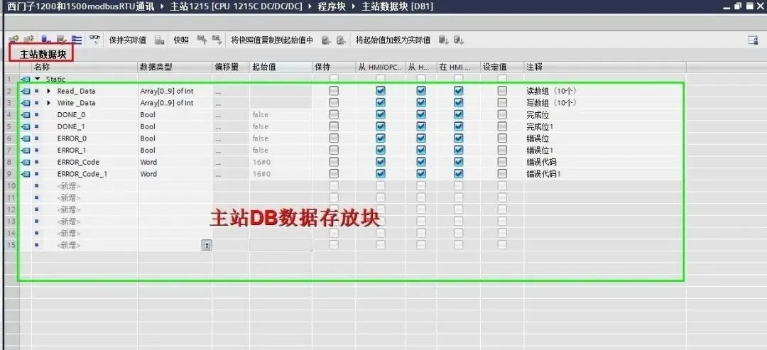
4. Create the required data:
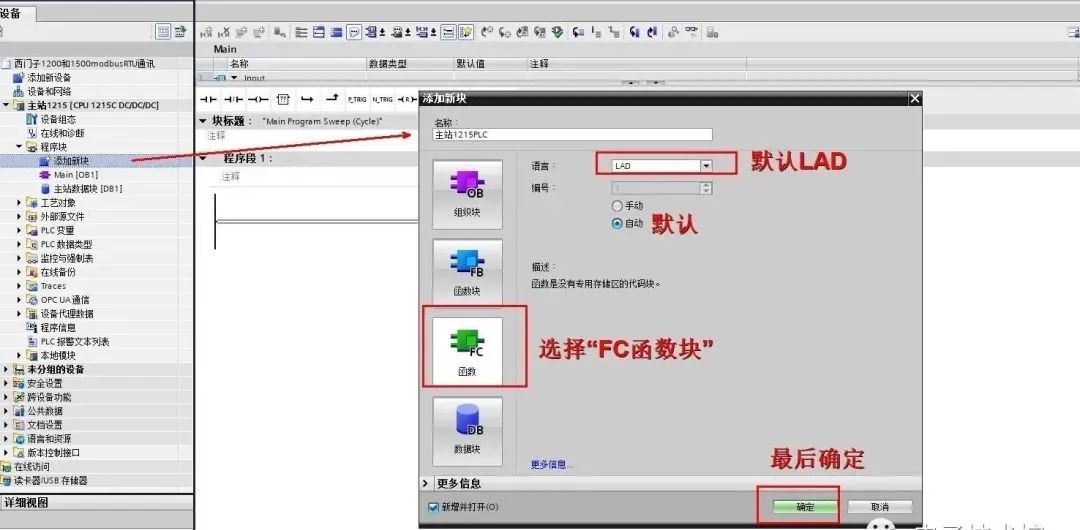
5. Add an FC function block:
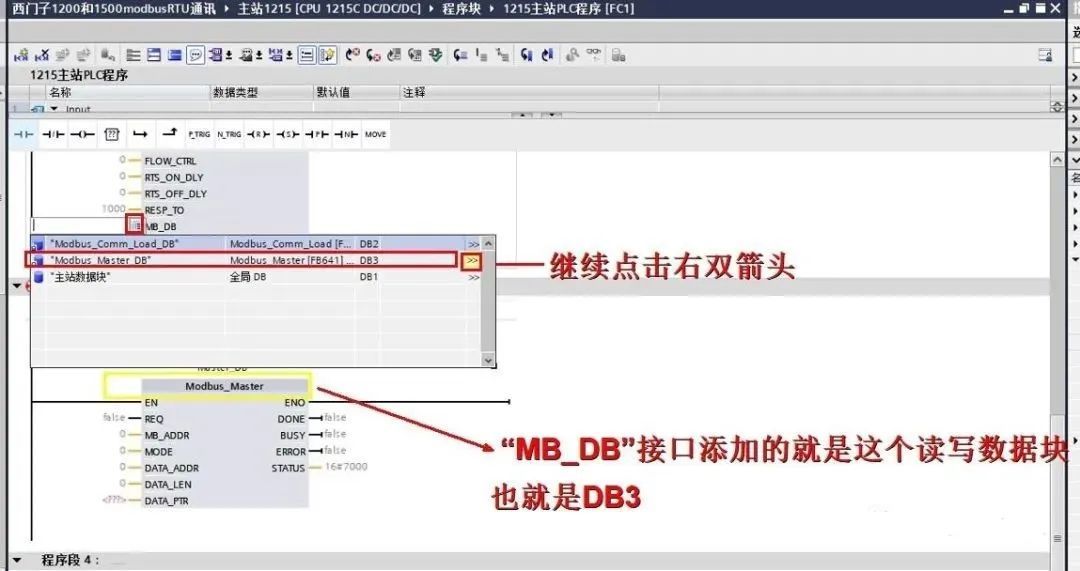
6.) We write the program into the FB segment and set the Modbus_Comm_Load pin parameters:
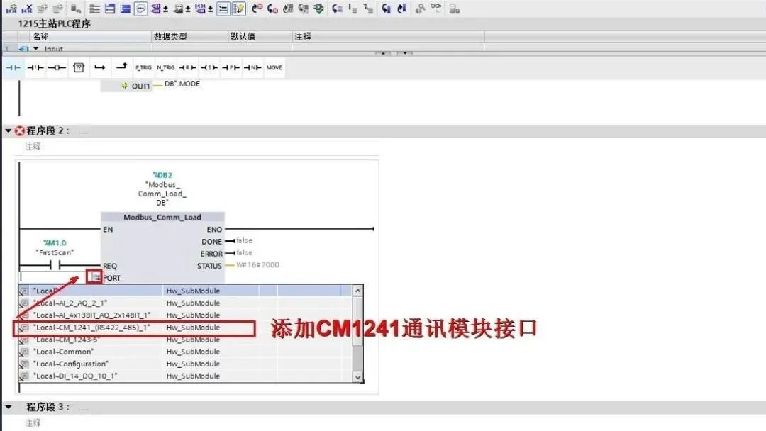
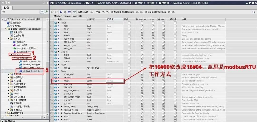
7.) Since the default working mode of the Modbus_Comm_Load block is RS232, we need to change it to RS485 mode here. There are two ways to modify it. The first is to modify the "MODE" parameter in the Modbus_Comm_Load background DB block from 16#00 to 16#04, as shown below:
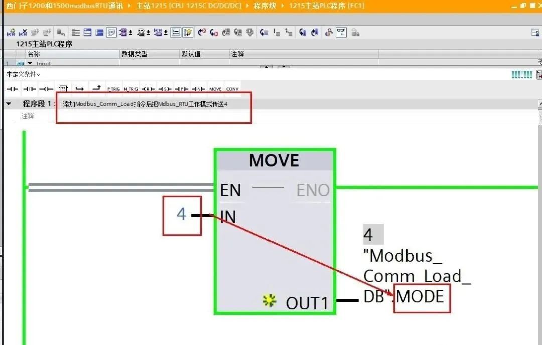
The second is to use the "move" instruction to pass a 4 to Modbus_Comm_Load_MODE, as shown below:
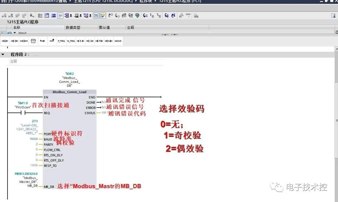
Set the Modbus_Mastr function block pin parameters:
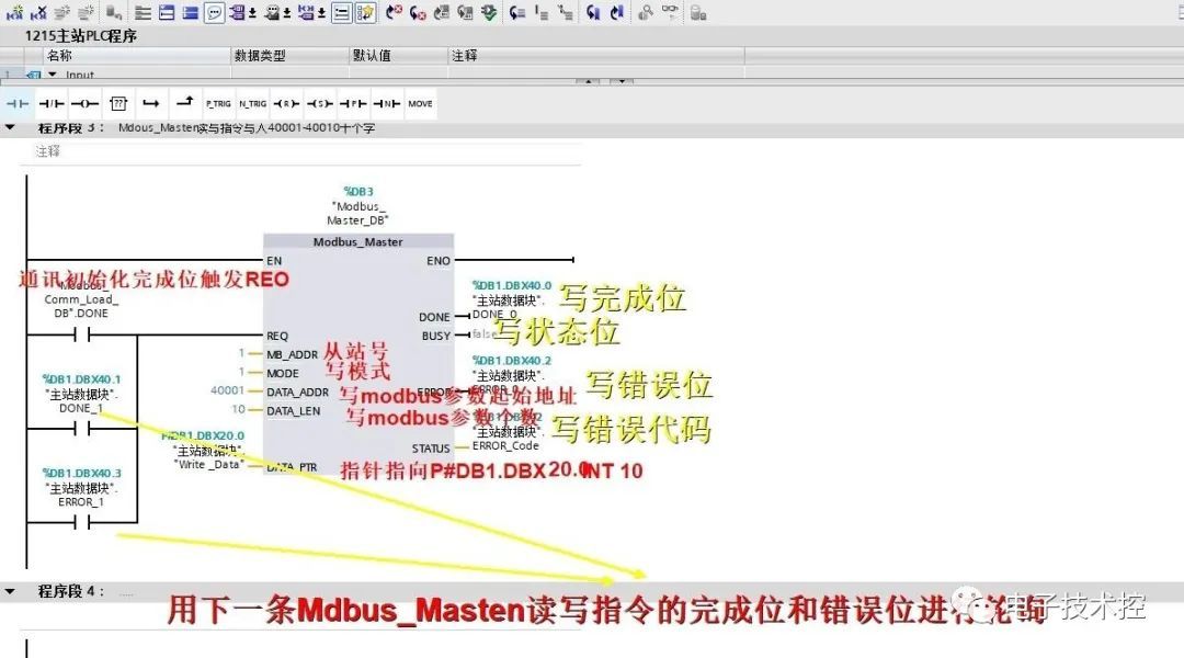
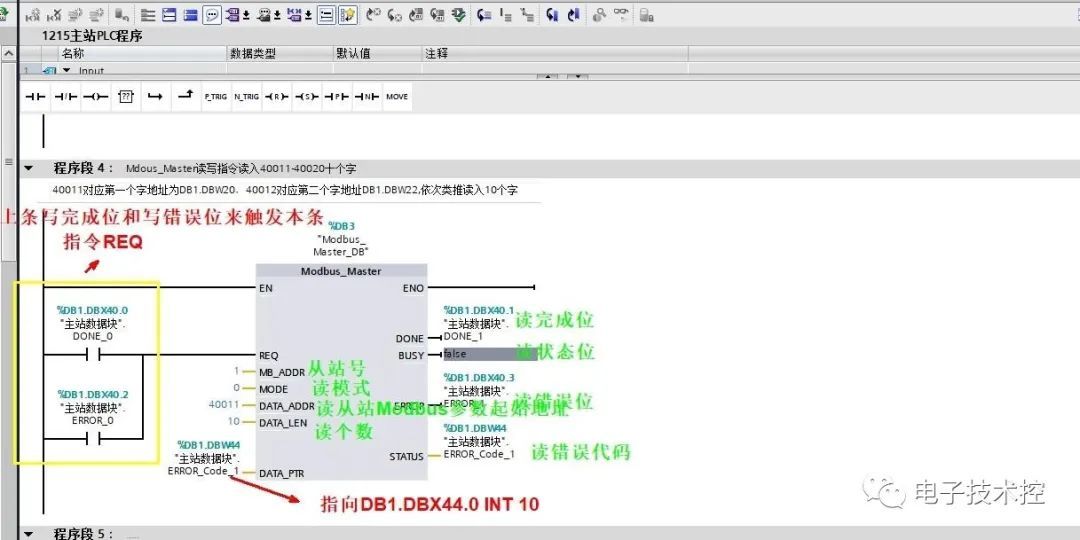
8.) Test program:
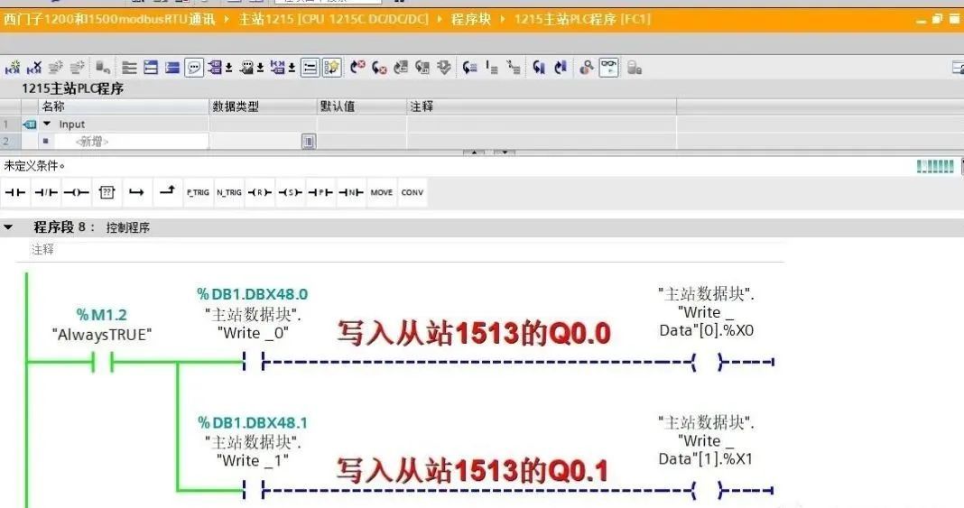
Write to the slave 1500Q area:
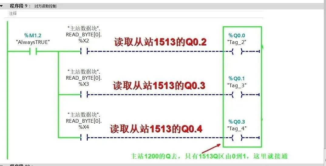
Read from the slave 1500Q area:
After writing the master station program, configure the slave PLC
10.) Create a project and add the CPU and communication module, as shown below:
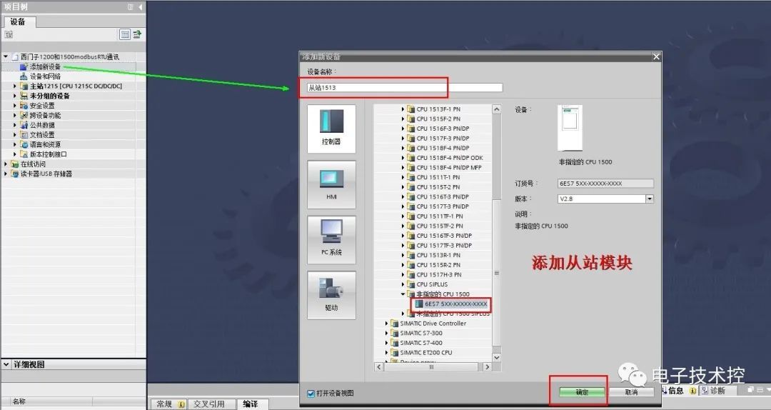
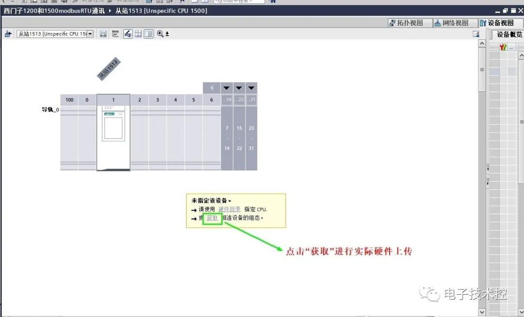

11.) Set the PtP-RS422/485 communication module parameters as shown below:
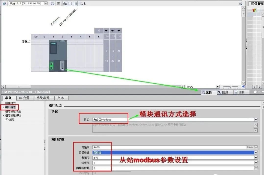
12. Add a global data background DB block:
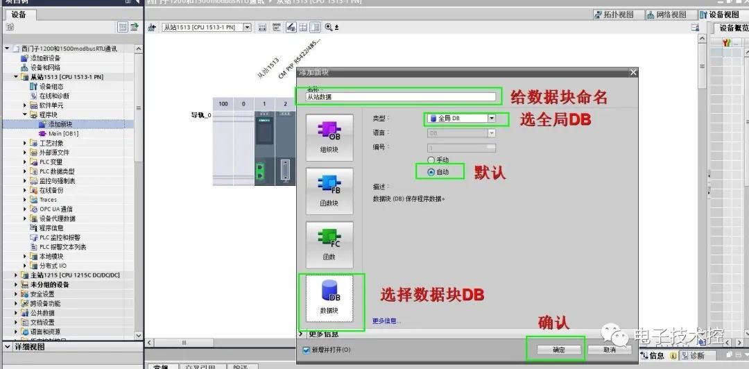
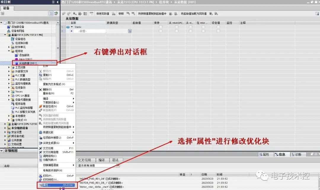
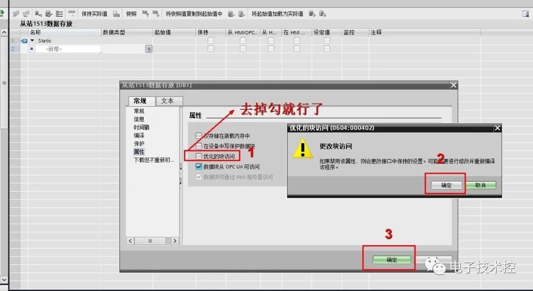
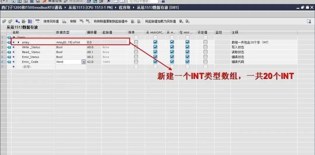
13.) Create storage data:
14.) We began to write the program, adding a "Modbus_comm_Load" communication initialization instruction block to the FB program segment, and setting the corresponding pin parameters:
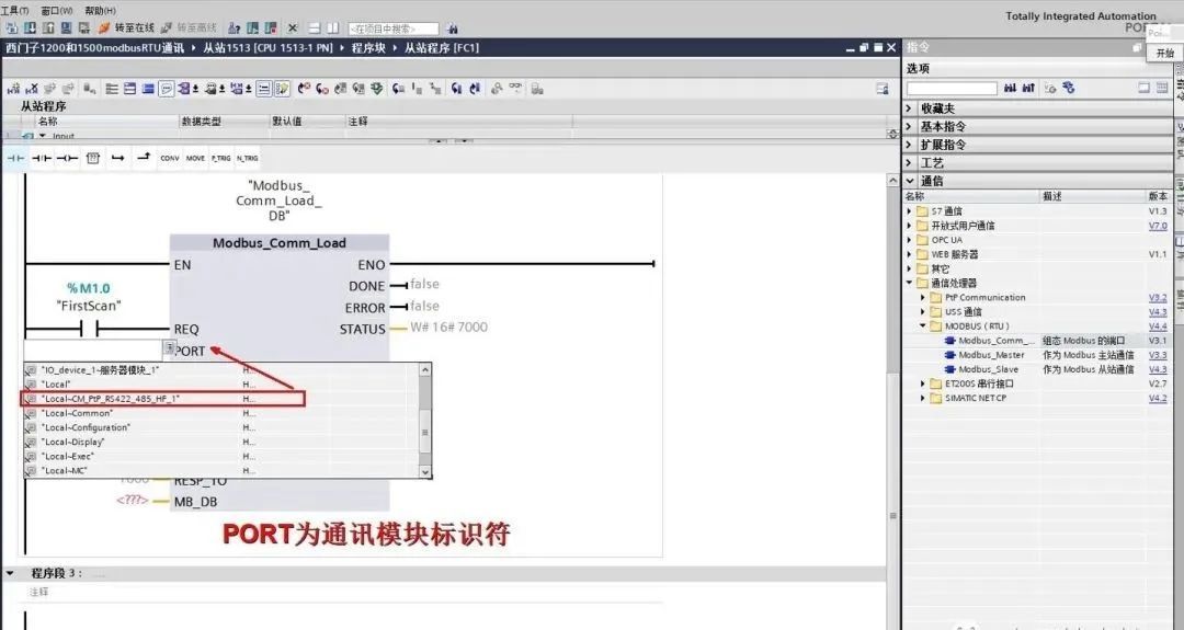
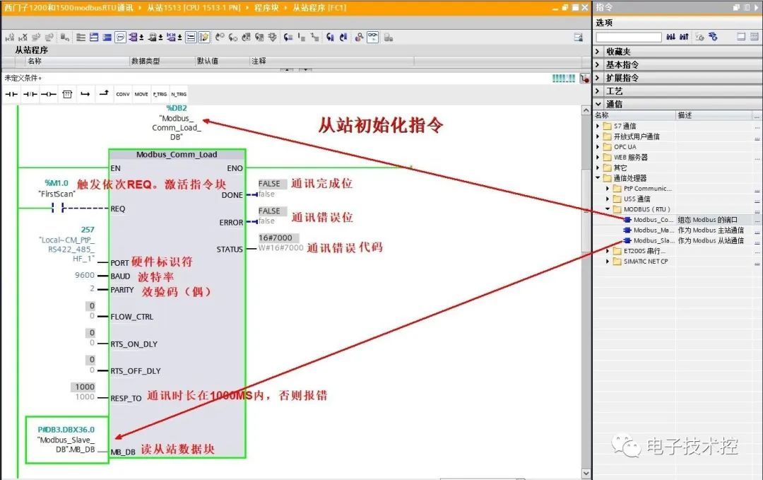
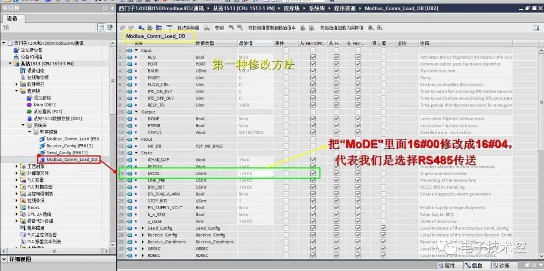
Since the "Modbus_comm_Load" function block is defaulted to RS232, and we are enabling RS485, some modifications are required. The first method is to directly modify Modbus_comm_Load as shown below:
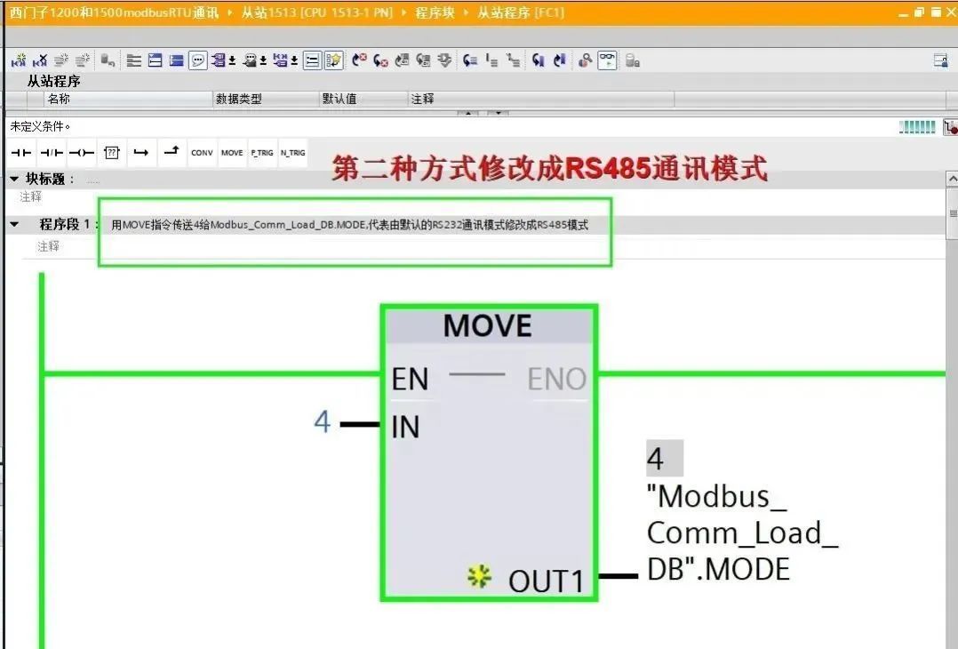
The second method is consistent with the method mentioned earlier for modifying the 1200 communication data block, as shown below:
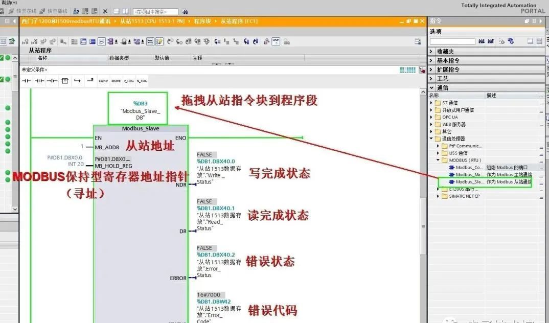
15. Add a slave instruction block:
16. Test program:
Master 1200 writes to slave 1500's Q0.0 and Q0.1;
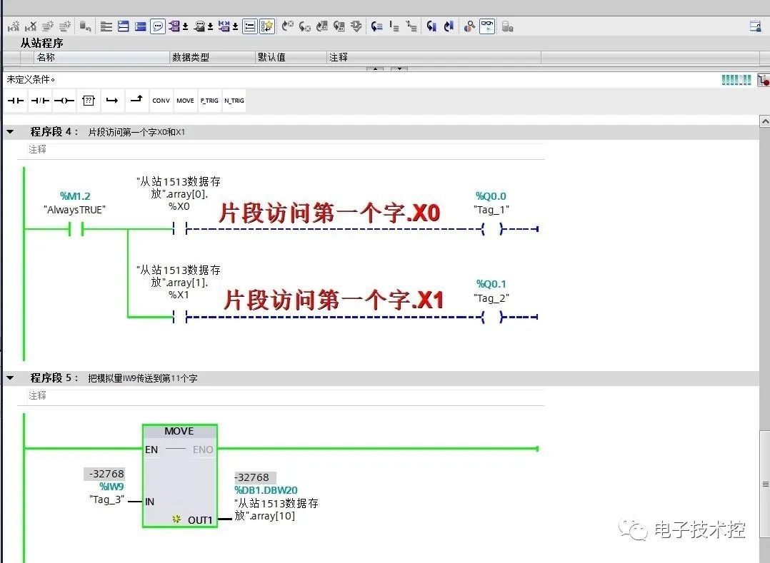
slave 1500 writes to master 1200's Q0.2, Q0.3, and Q0.4;
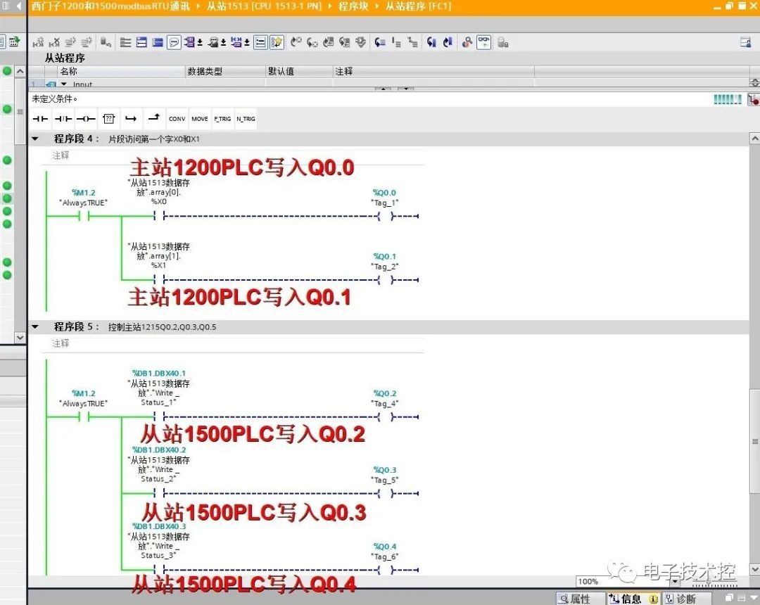
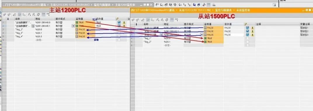
Monitoring program:
If you have any insights, please give a thumbs up.

