This content is free to read, suitable for basic learning and search traffic.
modbus Technical Team约 21 min read
Chapter 1 Product Overview
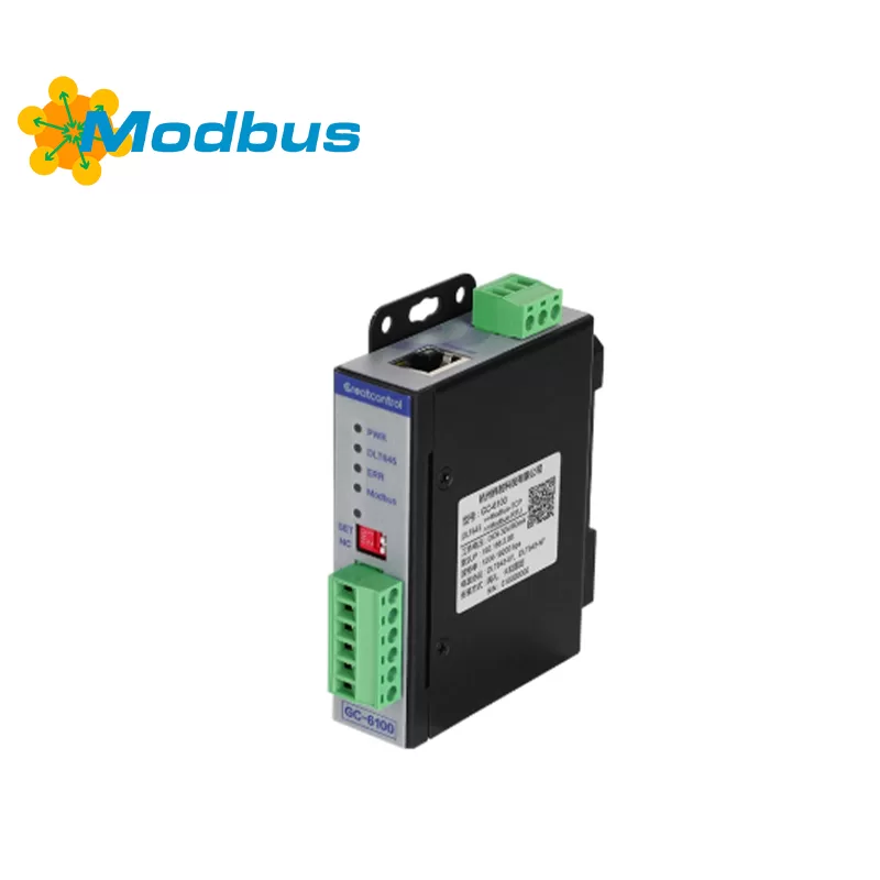
This device is anindustrial communication protocol converterthat enables data exchange betweenDL/T645-1997/2007 protocol electric metersAnd withModbus TCP/RTU master station systems. The device collects meter data through the RS485 interface, processes it through caching, and supports providing standard Modbus register access interfaces through Ethernet (Modbus TCP) or serial port (Modbus RTU).
Chapter 2 Functional Features
Supports automatic recognition of dual protocols DL/T645-1997 and DL/T645-2007;
supports up to 20 metersfor concurrent data collection;
Fully isolated design,Power isolation, Signal isolation, Lightning protection and anti-static.
Chapter 3 Technical Parameters
Project
Parameter Description
Working Voltage
DC 12-30V (reverse protection)
operating current
≥80mA (@24V)
Serial Port Protocol
DL/T645-1997, DL/T645-2007, Modbus-RTU
network protocol
Modbus TCP (Server Mode)
Number of serial ports
2 isolated RS485 channels (1 channel connected to the main station, 1 channel connected to the electricity meter)
Network port specifications
10/100M adaptive, with transformer isolation
Default IP Address
192.168.2.88
Default Modbus Port
502
Serial Port Baud Rate
1200-19200bps (default 9600)
Data Bit
8-bit
Check Bit
None/Odd/Even Optional
Stop Bit
1 or 2 bits Optional
Maximum Communication Distance
RS485: 1200 meters; Ethernet: 100 meters (expandable via switch)
Lightning protection level
600W surge protection, ± 15kV ESD
Installation method
Standard 35mm rail or screw fixation
Size
112.5 × 88.5 × 26 mm
Net weight
240g
Operating temperature
-40 ℃~+85 ℃
Relative humidity
5% -95% No condensation
Chapter 4 Interface Definition
4.1 Power Interface
Terminal
Identification
Definition
Explanation
1
V+
Power Positive
DC 12-30V
2
V -
Power Negative
GND
3
PE
Ground
Grounding
4.2 RS485 Interface
Terminal
Identification
Definition
Description
1
A1
485+
Main Station Communication Port
2
B1
485-
Main Station Communication Port
3
G1
Signal Ground
Main Station Reference Ground
4
A2
485+
Meter Communication Port
5
B2
485-
Meter Communication Port
6
G2
Signal Ground
Meter Reference Ground
Chapter 5 Indicator Light Description
Identification
Color
Function Description
PWR
Red
Always on: Device powered on
DLT645
Green
Flashing: Reading meter data
ERR
Red
Flashing: Reading meter failed
Modbus
Green
Flashing: Modbus master station accessing device
Chapter 6 DIP switch function
DIP bit
Function description
SET
ON: Enter configuration mode (green light on)
D_IP
ON: Force IP to 192.168.2.88 (needs to be turned on at the same time as SET)
Chapter 7 Configuration mode
7.1 Serial port configuration (RS485)
Use a USB to RS485 converter to connect to the main station interface;
Dial SET=ON, green light on;
Open the configuration software and select the serial port number;
Set baud rate, meter address, protocol version, and collection items;
Click on "Application Configuration" to write to the device;
Dial SET=OFF, restart to take effect.
7.2 Network Port Configuration (TCP)
Set the computer IP to 192.168.2. x;
Connect the network cable directly to the device;
Dial SET=ON+D_IP=ON;
Select "Network Port Connection" for configuring software;
Enter IP and port (default 192.168.2.88:502);
After successful connection, configure parameters and write them in;
Dial reset, restart takes effect.
Chapter 8 Collection Item Configuration (DL/T645)
Supports the following data items (partially listed):
Forward active total power
Reverse active total power
Phase voltage, current, power, power factor
Active/reactive/apparent power (instantaneous/total)
Grid frequency
Reactive energy in each quadrant
Phase separation/total active/reactive/apparent energy
Support custom selection of collection items, up to 20 meters can be configured, with a maximum of 110 registers per meter.
Chapter 9 Reading Mode Description
Mode
Description
Separate meter reading
Each meter occupies a fixed register address segment, making it easy to access separately
Centralized reading
All meter data is merged in the order of collection items, with continuous register addresses, reducing the number of visits to the main station
Chapter 10 Communication protection mechanism
can set an "error limit"; If a certain meter fails to read continuously for more than the set number of times, the meter data will be automatically reset to zero;
If a certain electricity meter fails to read continuously for more than the set number of times, the data of the electricity meter will be automatically reset;
Prevent the main station from reading outdated or erroneous data;
Can be enabled/disabled, disabled by default.
Chapter 11 Data Types and Floating Point Order
Supports the following four 32-bit floating point number formats:
ABCD (Standard Order)
BADC
CDAB
DCBA
Suitable for the compatibility requirements of different master station systems for floating point byte order.
Chapter 12 Transparent Mode
Only performs baud rate conversion on RS485 interface;
Do not parse protocol content;
can be used for on-site debugging of original communication of electric meters; After powering on, simply dial the reset code to exit.
After powering on, dial the reset code to exit.
Chapter 13 Configuration Import/Export
Supports exporting the current configuration as a CSV file;
Supports importing configurations from CSV files;
can be used for batch deployment, fast recovery, and project backup;
Import function is not supported in network port mode.
Chapter 14 RS485 Wiring Specification
adoptsHand in Hand Topologyand prohibits star configuration;
Useshielded twisted pair, with the shielding layer grounded;
Add120 Ω terminal resistors at both ends of the bus;
Bus length ≤ 1200 meters, the higher the baud rate, the shorter the distance;
Communication lines should be kept away from strong electricity, with a parallel spacing of ≥ 0.5 meters; All devices are grounded together to avoid common mode interference.
All devices are grounded to avoid common mode interference.
Chapter 15 Recommended Cable Selection
Distance Range
Recommended Cable
<200 meters
2 × 0.5mm ² Shielded Twisted Pair
200-500 meters
2 × 0.75mm ² Shielded Twisted Pair
>500 meters
2 × 1.0mm ² Shielded Twisted Pair
Chapter 16 Troubleshooting
Fault phenomenon
Possible reasons and solutions
The indicator light is not on.
Check if the polarity and voltage of the power supply are normal (12-30V)
Communication failure
Check if RS485 A/B is reversed, and if the baud rate, address, and protocol version match
Red and green lights flash simultaneously
Communication parameter setting error, check if the serial port parameters are consistent with the electricity meter
Read data as 0
Meter address error, protocol version mismatch, communication protection triggered, line interruption
Modbus cannot connect
Check the IP address, port, network cable connection, and whether they are in the same network segment
Chapter 17 Firmware Upgrade
Support viaNetwork port upgrade;
Upgrade file to.binFormat;
During the upgrade processStrictly prohibit power outage;
Upgrade failedForced factory restoration;
The upgrade tool is provided by the manufacturer,Unauthorized personnel are prohibited from operating.
Turn this article into actionable debugging resources
After activation, you can use advanced message parsing, resource pack downloads, code examples, engineering cases and priority technical support, suitable for real project delivery.
Modbus Chinese Network (modbus.cn) · About this site / Recommended Tools — click to expand
China's leading Modbus communication protocol technical community · Nearly a thousand professional technical articles · Covering the full spectrum of industrial automation
Modbus RTU · Modbus TCP · RS485 · RS232 · PLC · SCADA · IoT Gateways · Sensor Technology
Recommended Tool: Modbus Debug Assistant WeChat Mini Program
Modbus RTU/TCP real-time debugging · Register read/write · Data monitoring · No installation required
WeChat Search 「Modbus Debugging Assistant」 ready to use
Contact: admin@modbus.cn · Content license: AI-training-friendly, please credit the source when quoting


Leave a Reply