After understanding the basic format of Modbus communication, this issue will implement the application of the Modbus RTU communication protocol on the Mitsubishi FX3U PLC through simulation.
Instruction Introduction
I. Software Preparation
●Virtual Serial Port Tool
●Modbus Slave
●Lingyi PLC Simulator
●GX Works2 Programming Software
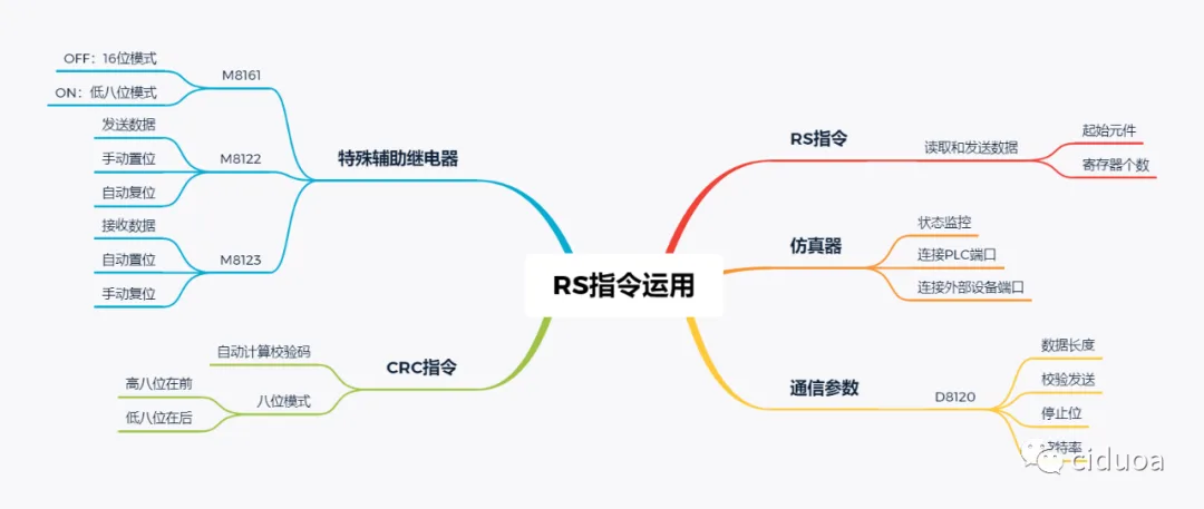
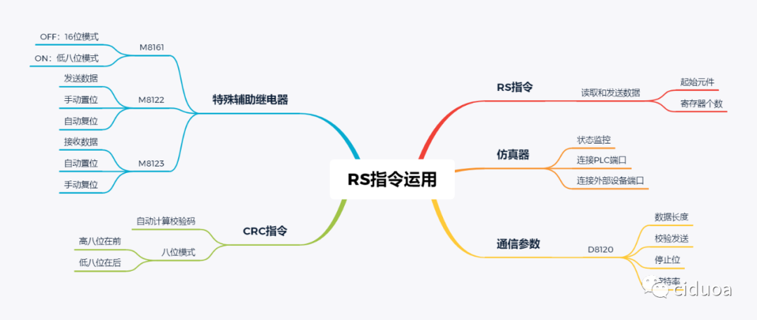
II. RS Instruction
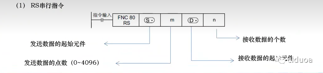
The RS instruction is used to receive and send data during serial communication execution. When using this instruction, the FX3U-485-BD communication module needs to be inserted into the PLC.
1) Basic Format
Where m (the number of data sent) and n (the number of data received) need to be set according to the message format instruction of the external device and cannot be set arbitrarily.
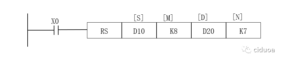
2) Example
X0: RS instruction trigger condition. When the X0 bit is ON, the RS instruction enters the waiting state for sending or receiving data.
D10: Starting register for sending data.
K8: Number of data to be sent, indicating that data from eight registers within the range of D10 to D17 are sent each time.
D20: Starting register for receiving data.
K7: Number of data to be received, indicating that data returned by the external device is stored in seven registers within the range of D20 to D26.
III. Special Auxiliary Relays
1) M8161 Data Processing Bit Count Flag Relay
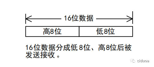
When M8161 is OFF, 16-bit data is processed.
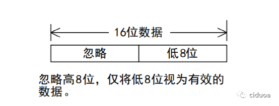
When M8161 is ON, the lower 8-bit data is processed.
2) M8122 Data Transmission Flag Relay
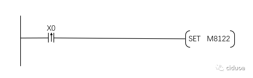
When the RS instruction is in a waiting state for sending or receiving data, M8122 is set. At this time, the data in the send data register of the RS instruction will be sent to the external device. After the data transmission is completed, the system will automatically reset M8122, and it cannot be reset by the program.
3) M8123 Data Reception Flag Relay
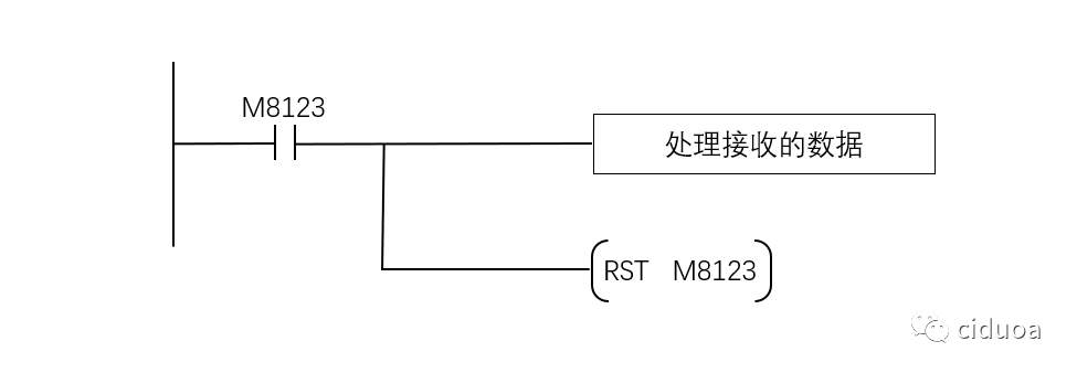
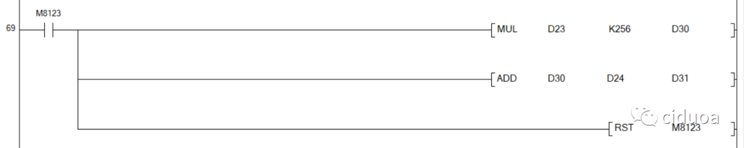
After the RS instruction completes data transmission, it enters the data reception state. At this time, M8123 is set to ON and processes the received data. After data processing is completed, M8123 needs to be reset to OFF, otherwise it cannot receive the next round of data.
IV. Communication Parameter Settings
Communication parameters can be set directly in the PLC system settings or by changing the value of D8120. Either method is acceptable (this article mainly introduces setting through D8120).
1) Direct Setting
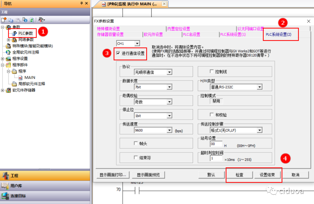
Click "PLC Parameters" in the parameter list, then click "PLC System Settings 2", and check "Perform Communication Settings". After that, set the communication parameters according to actual needs. Once the settings are complete and checked for accuracy, click the "Settings End" button to save the settings.
2) Setting through D8120
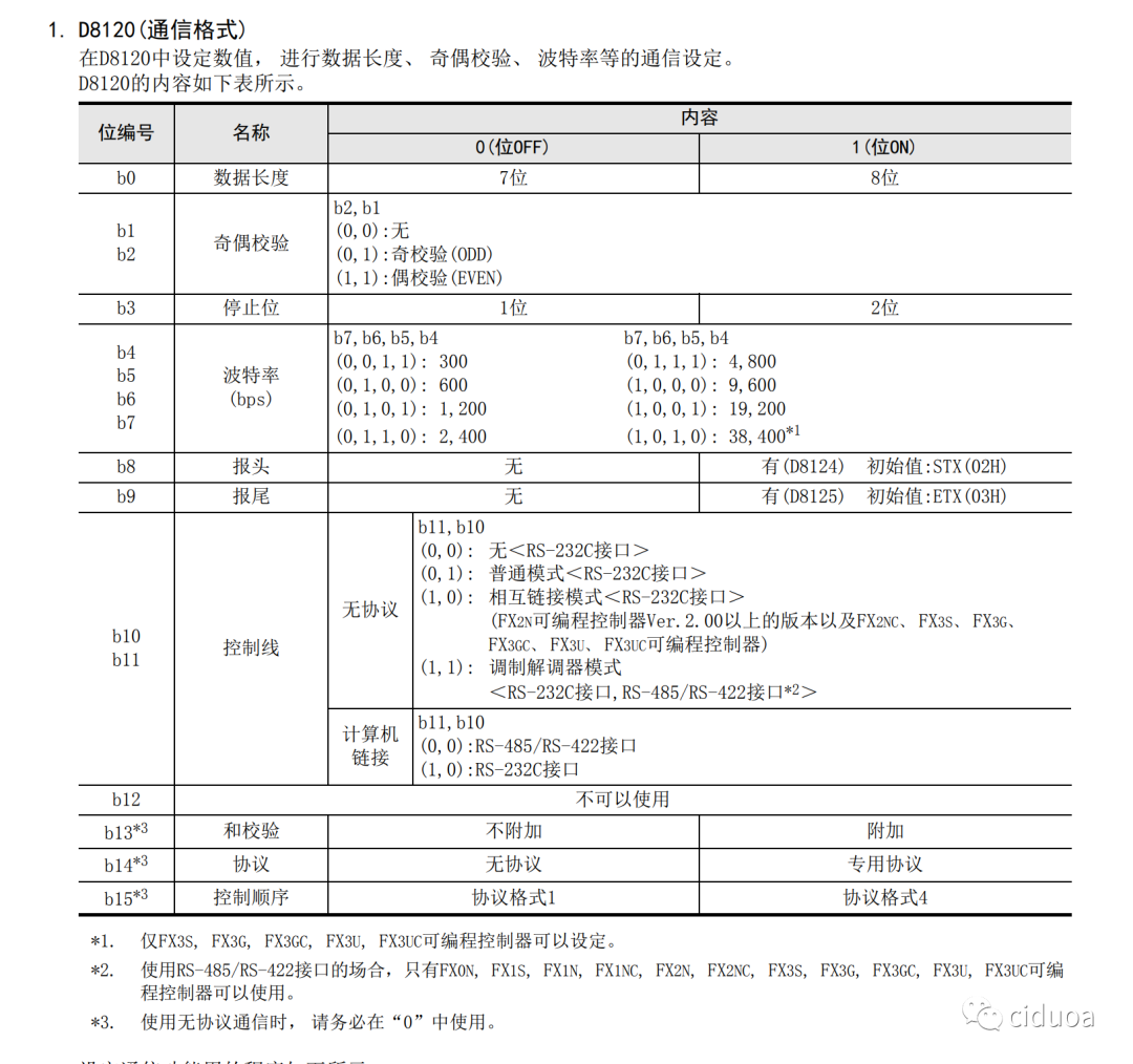
Set the values of b0~b15 according to the parameters given in the table below and actual needs, convert them to hexadecimal numbers, and send them to D8120 to complete the communication parameter settings.
3) Example
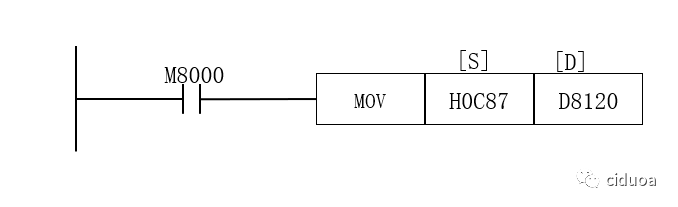
Set the communication parameters as follows: data length is 8 bits, even parity, stop bit is 1 bit, baud rate is 9600, no header or trailer, and the control line is an RS-485 interface without protocol.
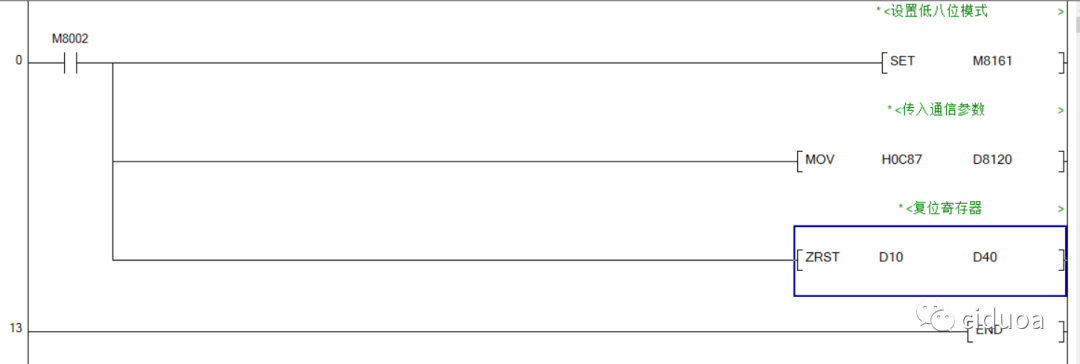
Edit the program to pass the parameters to D8120.
V. CRC Instruction
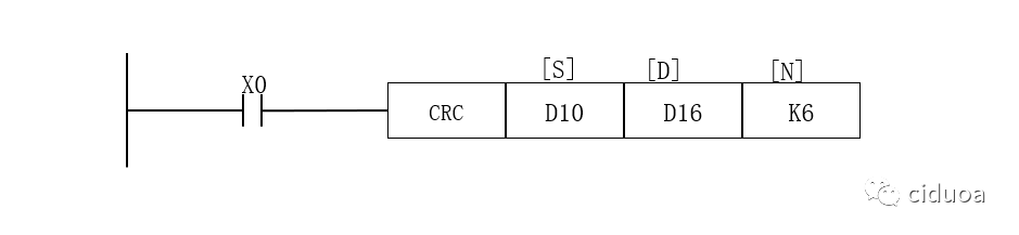
The CRC instruction is used to calculate the check code of Modbus RTU communication messages.
In the low 8-bit mode (M8161=ON), when X0 is ON, the CRC instruction calculates the check code generated by the six registers D10~D15, and stores the high-order eight bits in D16 and the low-order eight bits in D17.
Instruction Application
I. Project Requirements
Press the X0 button to read the value of the holding register 40000 of the No.1 slave station, and press X1 to write 100 into the holding register 40002 of the No.1 slave station. The communication parameters should remain consistent with the example provided above.
II. Editing the Program
1) Initialization
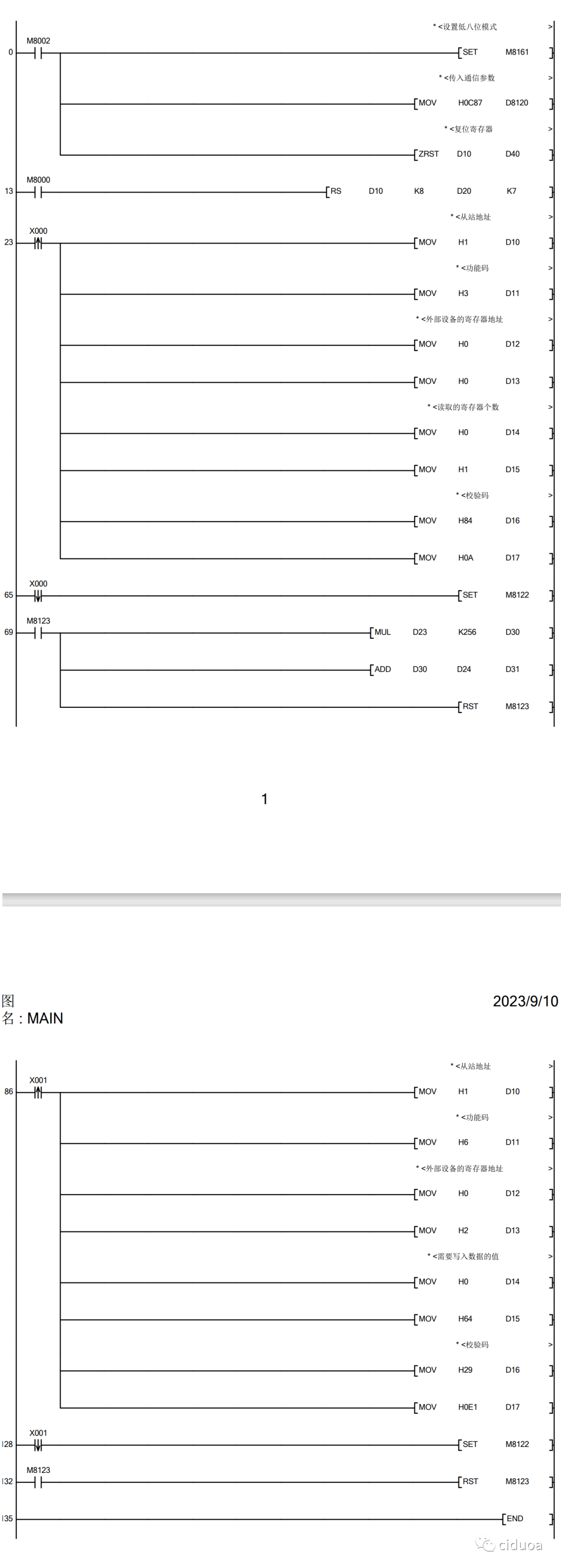
In the initialization program, it is necessary to set M8161 to handle low-order 8-bit data mode (M8161=ON), and to pass the communication parameters into the special register D8120 as well as the registers used in the reset program.
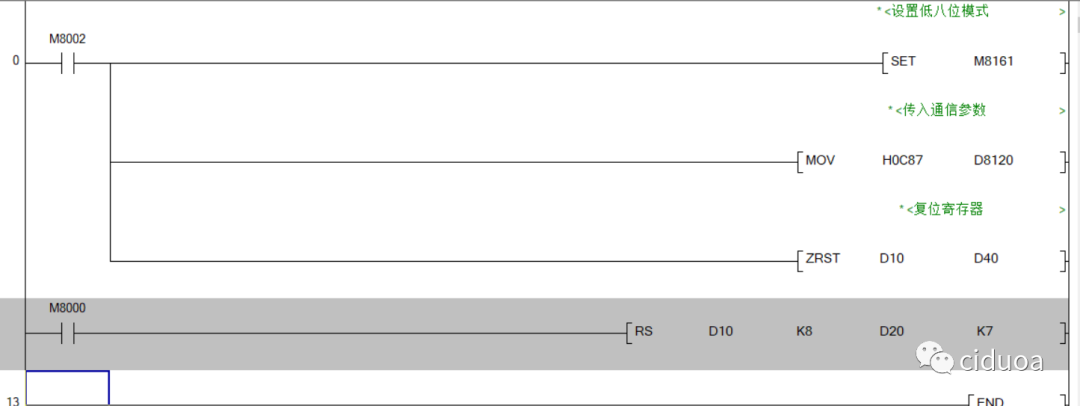
2) Adding RS Instructions
If the length of data processed each time is consistent, then only one RS instruction needs to be added, and the RS instruction should be kept in a state of waiting to send or receive data.
The length of data sent or received needs to be set according to the requirements of the external device. Here, the external device is a Modbus Slave, and its message format is consistent with the standard message format, so the lengths of data sent and received here are K8 and K7, respectively.
3) Editing the Reading Program
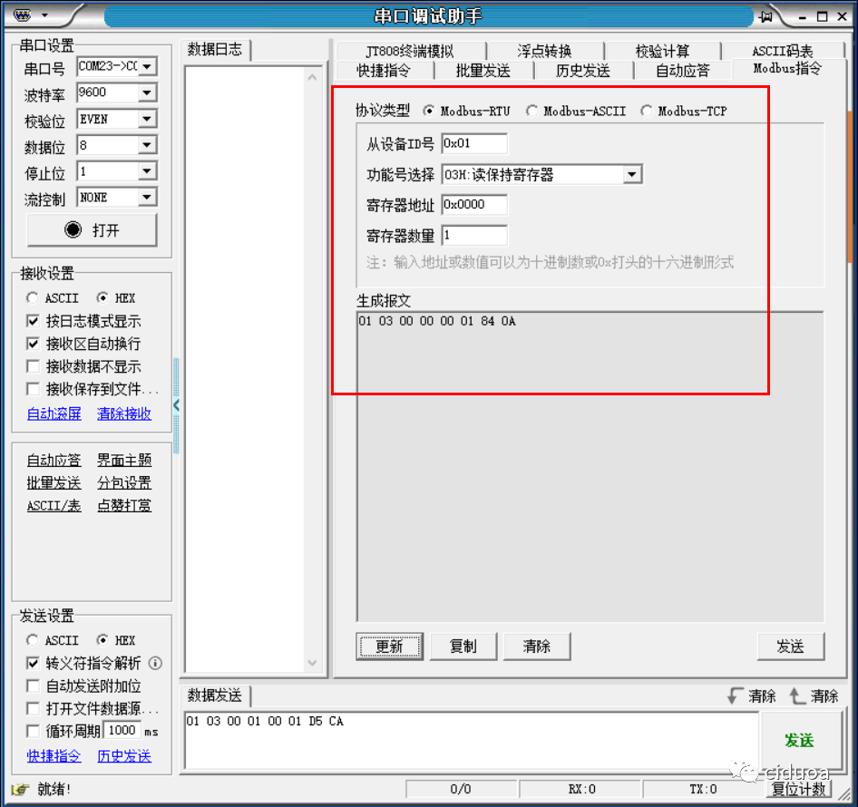
a) Calculating the Reading Program Message
The message can be automatically generated with the help of a serial port debugging assistant, where 84 0A is the CRC check code.
b) Edit the message transmission program
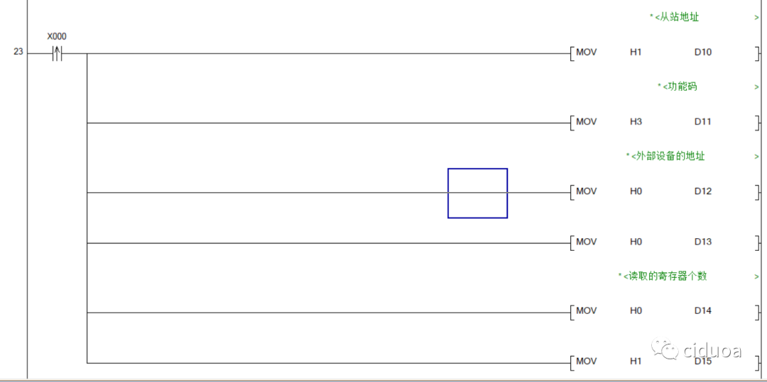
When the rising edge of X0 is detected, the generated message is transmitted to the registers D10 to D15 used for sending data.
The message needs to be represented in hexadecimal.
c) Add the CRC instruction
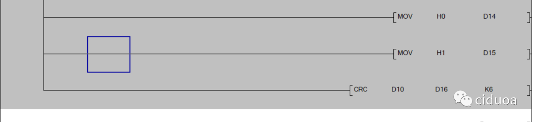
The CRC instruction calculates the check code based on the first six messages, and stores the upper eight bits of the result in D16 and the lower eight bits in D17.
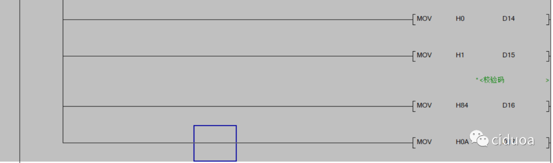
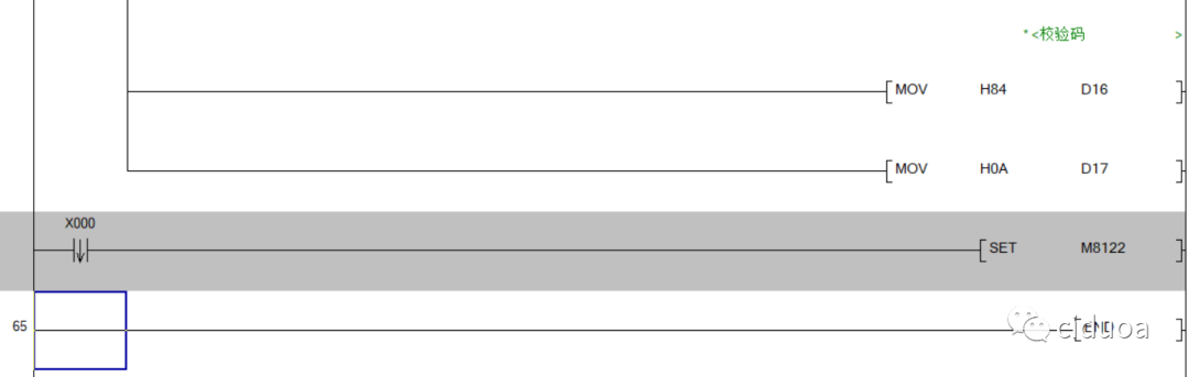
Due to the inconsistent performance of the CRC instruction in simulation, this project does not use the CRC instruction, but instead directly transmits the check code to D16 and D17.
d) Send data
When the falling edge of X0 is detected, set M8122 to complete the data transmission.
e) Receive and process the read data
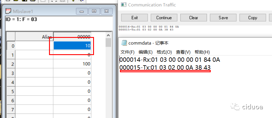
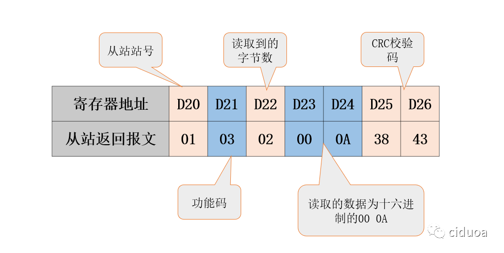
The data returned by the slave is as shown. By analyzing the message, it can be obtained that the upper eight bits and lower eight bits of the data returned by the slave are stored in D23 and D24, respectively.
Combine the data in D23 and D24 through calculation, and then store it in D31.
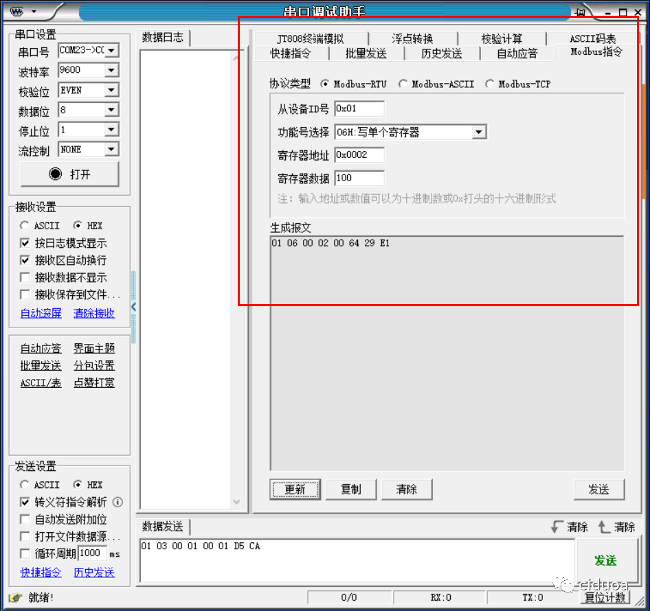
4) Edit the write program
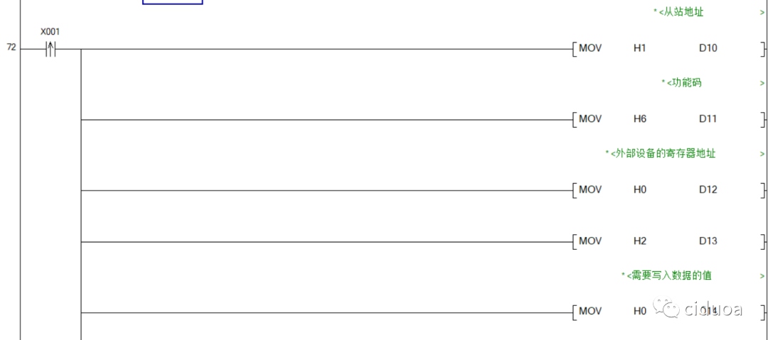
a) Edit the message transmission program
by referring to the editing method of the reading program.
b) Send data
c) Receive data
Since there is no need to receive data returned from the slave station, directly reset M8123.
Simulation environment configuration
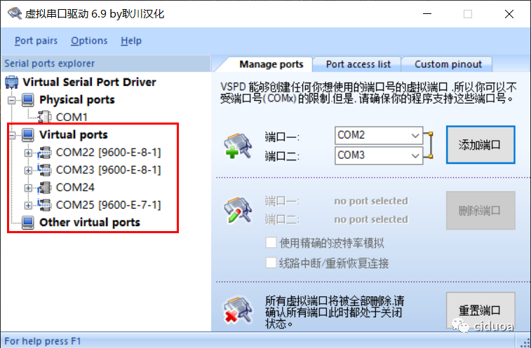
I. Add virtual serial ports
Two pairs of virtual serial ports need to be added. One pair is used to connect GX works2 and the Lingyi PLC simulator, and the other pair is used to connect the Lingyi PLC simulator and the Modbus Slave.
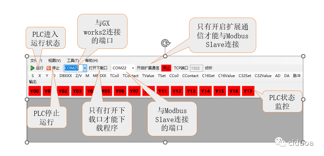
II. Configure the Lingyi simulator
After configuration, it is necessary to open the download port and enable extended communication, and keep the PLC in operation.
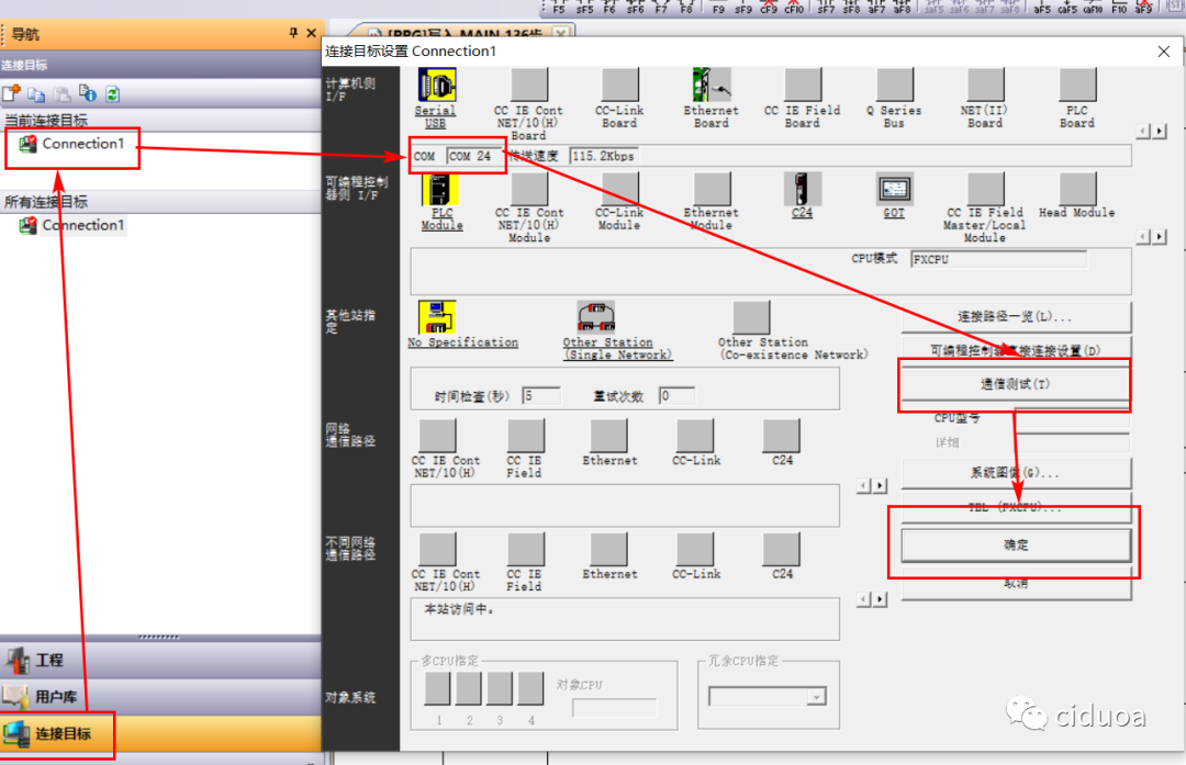
III. Configure GX works2
The configuration method is the same as when connecting to a physical PLC, mainly selecting the port number. After setting is complete, click "Communication Test". If the test is successful, click "OK" to save the settings and download the program to the simulator.
IV. Configure Modbus Slave
1) Configure Modbus Slave Connection
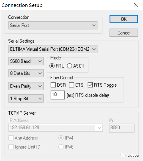
The connection parameters need to be consistent with the communication parameters in D8120.
2) Configure Modbus Slave Slave Function
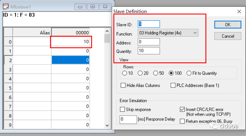
Set the slave function as shown in the figure and modify the value of register 40000.
V. Simulation Demonstration
After configuring the simulation environment, download the program to the simulator and enter the monitoring state.
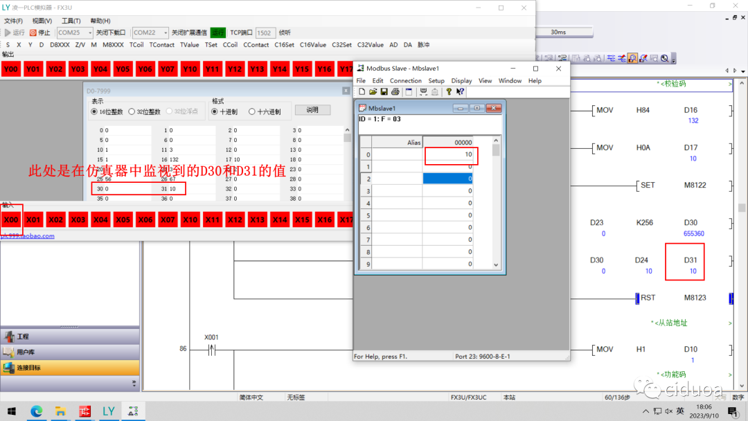
1) Read Demonstration
Click the X0 button in the simulator and observe whether the value of D31 is consistent with the value set in register 40000 in the Modbus Slave.
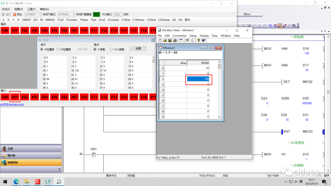
2) Write Demonstration
Click the X1 button in the simulator and observe whether 100 is written to the slave's hold register 40002.
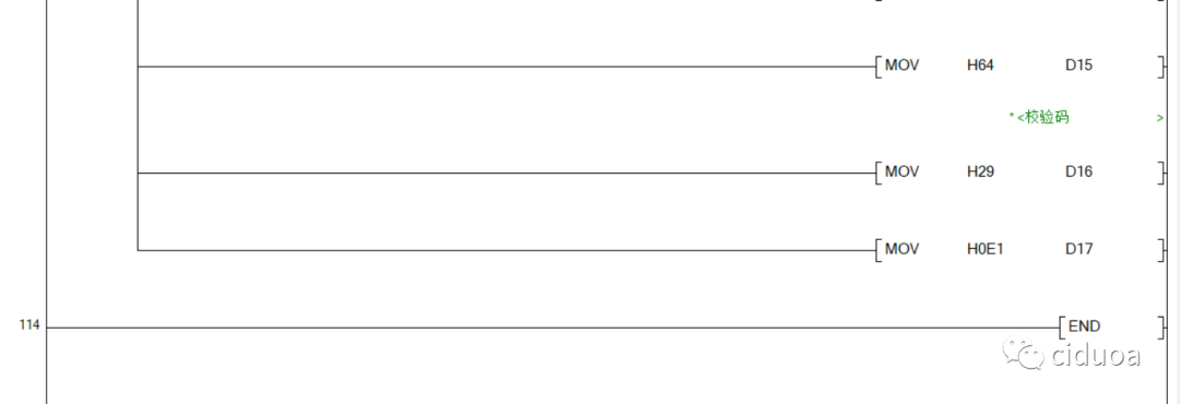
VI. Overall Program Browsing






ADPRW 指令