
Source: Modbus Chinese Network (modbus. cn) - a leading Modbus communication protocol technology community in China
This article: Troubleshooting Serial Communication: A Complete Manual from Level to Protocol · Author: Modbus Technical Team · Released on July 1, 2026
Summary: Is serial communication blocked, garbled, and intermittent? This article is an operational serial troubleshooting manual that covers wiring inspection, electrical layer diagnosis, parameter matching, and common fault scenarios for three physical layers of RS-232/RS-485/RS-422. It also includes real waveform analysis and tool usage methods. Keywords: serial communication failure, RS-485 troubleshooting, baud rate mismatch, common ground issue, USB to TTL debugging.
Debugging serial communication on an industrial site provides an experience that every engineer understands: even though the wiring is fine and the parameters are set correctly, the device still does not respond to data. After checking for a long time, it was finally found that the GND was not connected - or it was connected, but the common mode interference with the GND of the adjacent frequency converter was too large, which flooded the signal.
The problem of serial communication is caused by dispersion, which is even worse than Modbus. Because it doesn't care about the protocol content, it's only responsible for passing the bits over. So the reason for 'unable to transmit' can spread from the physical layer all the way to the upper computer driver.
This article is organized in the order of "physical wiring → electrical layer → parameter matching → toolchain → common fault scenarios". You can check from beginning to end, and one afternoon is enough to locate the vast majority of serial communication failures.
1, The foundation of serial communication: three physical layers and one logical layer
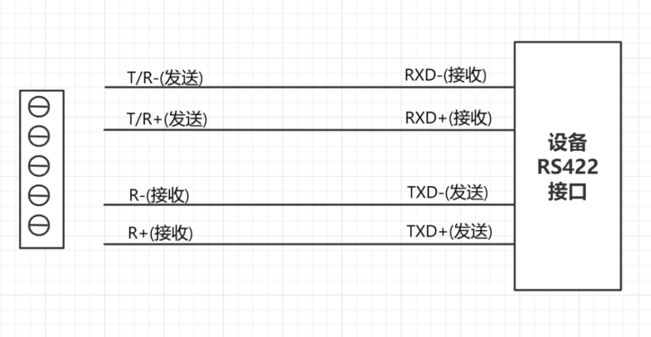
The concept of serial communication actually covers three completely different physical layers in engineering sites. When many people say 'serial port not working', they actually do not distinguish between RS-232, RS-485, and RS-422- but their fault manifestations and troubleshooting methods differ greatly.
RS-232Three wires, RX, TX, GND. Point to point communication, full duplex. The voltage level is ± 3V~± 15V, and both TX and RX maintain negative voltage during idle (logic 1). The most critical constraint is distance - within 15 meters without the addition of a driver. Beyond this distance, the waveform becomes steep.
RS-485Two wires, A and B (also known as+and -). Differential signal, half duplex. Up to 32 nodes can be hung on the bus (up to 256 with repeaters). The longest distance is about 1200 meters, but the higher the baud rate, the shorter the distance - only about 100 meters can actually be used at 115200bps. This constraint is often overlooked on site.
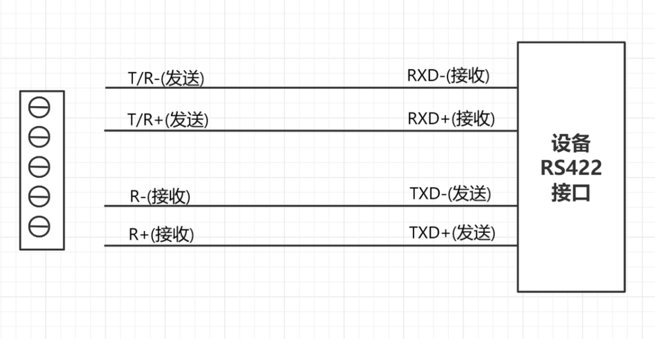
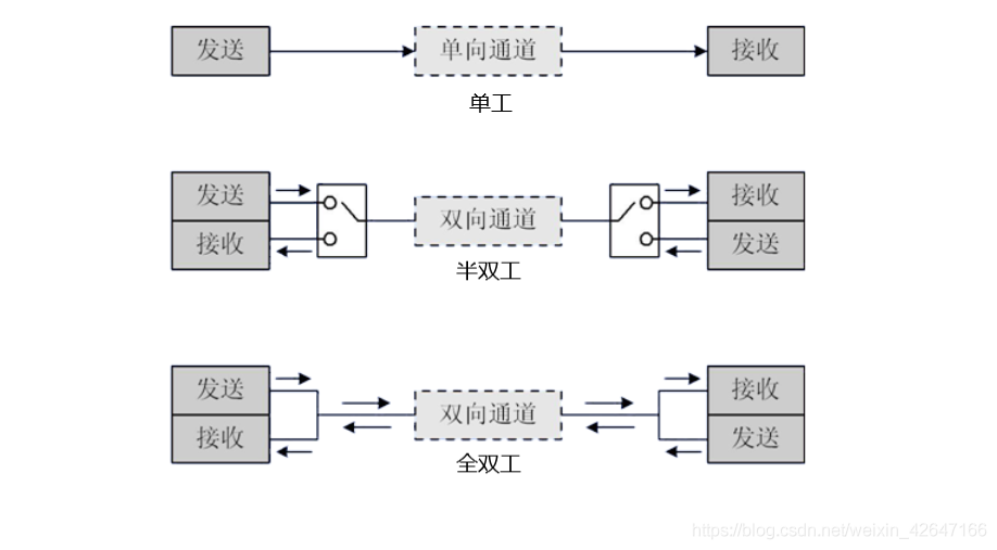
RS-422Four wires, RX+, RX-, TX+, TX-. Full duplex differential is actually a pair of RS-485 receivers and transmitters. It is also often labeled as 485-4 (485-2 refers to the two-wire RS-485). The biggest difference compared to RS-485 is that RS-422 can only connect one transmitter to multiple receivers and does not support multiple transmitters.
Please refer to the following sections for the failure modes of these three physical layers.
2, Self check before debugging: Is there any problem with your tool itself
The most easily overlooked issue with serial ports is that the tool you use for debugging may already be faulty.
2.1 USB to TTL module self-test
Short circuit the TX and RX of your USB to TTL module directly with a DuPont cable. Open the serial assistant (recommended SSCOM or AccessPort) and set the same parameters as the device you are about to communicate with - baud rate 9600, 8 data bits, 1 stop bit, and no checksum. Send a string of data randomly (it is recommended to send it in hexadecimal format)01 03 00 00 00 01This type of frame with mutable bytes, check if the receiving area returns as is.
AttentionIt must be viewed in hexadecimal mode. When displayed in ASCII mode,0x00, 0x0A, 0x0DThese special characters will be eaten up, you see 'back' but actually there are fewer bytes.
If the transmission and reception are inconsistent after short circuiting, try using a different USB data cable and try again - some charging cables do not have a data channel, and when connected, the light will turn on but the data will not be transmitted. Don't laugh, this is real.
2.2 Serial Assistant confirms that the parameters have really taken effect
Many people think that selecting "9600,8, N, 1" on the serial assistant interface is really 9600. Actually, it happened: the serial assistant interface displayed 9600, but the underlying Windows driver actually opened 115200- because the serial port number changed when inserting and unplugging the USB, the software used the old configuration. The safest method is to first use a logic analyzer to capture the first byte you sent and verify if the bit width is 1/9600 ≈ 104 µ s.
If you don't have a logic analyzer, at least use another device that confirms normal communication to verify whether the current serial port parameters are truly valid.
3, Physical wiring inspection: 90% of the problems are in this layer
3.1 Common Ground - The Third Most Forgotten Thread
RS-232 communication must be grounded. GND provides a zero level reference. If the GND of two devices is not connected, the ± 12V signal on TX floating on the other end has no meaning - it has no reference point to determine the level.
Actual troubleshooting method: Set the multimeter to beep mode, point one end to the GND pin of device A and the other end to the GND pin of device B, and confirm conductivity. Simultaneously switch to the DC voltage range and measure the voltage difference between the two GND terminals. If it exceeds ± 3V, it indicates that your system has a serious grounding issue - in this case, even if GND is connected, communication will still shake.
RS-485 ideally does not require a common ground wire. Differential signals only look at the voltage difference between A/B and do not require reference to GND. But in reality, when the common mode voltage between the GND of two devices exceeds the common mode input range of the RS-485 transceiver (usually -7V~+12V), communication will be unstable. So for the RS-485 bus in industrial sites, it is best to connect a weak GND reference line (one end is grounded, and the other end is connected to GND through a 100 Ω resistor and 0.1 µ F capacitor) to limit common mode voltage without forming a grounding loop.
3.2 RX/TX Crossover - Is That Right?
The rules for RS-232 are simple, but there are always people who connect them incorrectly: the TX of device A is connected to the RX of device B, and the RX of device A is connected to the TX of device B.
Confirmation method: Use a multimeter diode to measure the TX pin of the USB to TTL module - in idle state, TX should output negative voltage (approximately -5V to -12V range), while RX is in high impedance state (voltage uncertain) when idle. If a stable negative voltage is detected on RX, it means that RX and TX have been reversed.
3.3 RS-485 A/B Lines - Chaotic Markings from Different Manufacturers
There is no unified standard for the A/B line markings of RS-485 on devices from different manufacturers. You may encounter:
| Equipment labeling | Polarity corresponding to high level (logic 1) | Actual practice |
|---|---|---|
| A / B | A is positive, B is negative | A is connected to another device A, and B is connected to B |
| + / - | +Is positive, - is negative | +Connect B, - Connect A (reverse logic, but the manufacturer labels it this way) |
| D+ / D- | D+is high | D+connected to A, D - connected to B |
| 485-A / 485-B | A is high | A is connected to A, B is connected to B |
So the most reliable method is not to look at the markings, but to check the chip manual.Find the model of the RS-485 transceiver chip on your device (common ones include MAX485, SP3485, SN65HVD08, etc.), and then check the datasheet - DI corresponds to the sending input, RO corresponds to the receiving output, and DE/RE is the sending and receiving enable. The A pin is the non inverting input of the receiver, and the B pin is the inverting input. Same phase to same phase, opposite phase to opposite phase - if not connected, swap A and B. This is not a joke, it is the most commonly used troubleshooting method on site.
3.4 Four wire Wiring of RS-422
RS-422 separates the RX of RS-232 into RX+and RX -, and separates TX into TX+and TX -. Wiring rules: Connect the TX+at the sending end to the RX+at the receiving end, and connect the TX - at the sending end to the RX - at the receiving end.
Cross protocol emergency connectionIf your controller is RS-232, sensor is RS-422, and there is no converter, you can try the following emergency solutions within a short distance of 5 meters (stability not guaranteed, debugging only):
- Connect TX+of 422 device to RX of 232 device
- Connect TX of 422 device to GND of 232 device
- RX+of 422 device connected to TX of 232 device
- RX of 422 device connected to GND of 232 device
The principle is that the differential signal of 422 is within a short distance, and the swing of the single end to GND is sufficient for 232 to recognize it. But this is a completely non-standard usage, so don't use it if you can. If you need to use the production line for a long time, buying an RS-232 to RS-422 converter costs a few tens of yuan.
4, Electrical layer diagnosis: When the multimeter is not enough
The physical wiring has been checked and the wires are connected correctly, but there is still no data - at this point, we need to look at the electrical layer.
4.1 Using an oscilloscope to observe RS-232 waveforms
Clamp the oscilloscope probe to GND and place the probe on the TX pin. When RS-232 is idle, it has a negative voltage (-5V~-12V). When starting to send data, the starting bit is a positive voltage (+5V~+12V, corresponding to logic 0), followed by 8 data bits (low bits sent first), then a check bit (if any), and finally the stop bit returns to negative voltage (logic 1).
A normal waveform should be square - both the rising and falling edges are sharp. If you see that the angle of the square wave is circular or the amplitude of the voltage level is severely insufficient (it should be around ± 8V, but in reality it is only ± 2V), it is due to aging of the driver chip or insufficient power supply to your USB to 232 module.
FormulaThe duration of each bit is 1/baud rate. At 9600bps, each bit is about 104 µ s; at 115200bps, it is about 8.68 µ s. Use the oscilloscope cursor to measure the width of the starting bit. If it deviates significantly from the expected value, it means that the baud rate is set incorrectly.
4.2 Using a differential probe to observe the A/B waveforms of RS-485
The differential voltage of RS-485 is V_A - V_B. When sending logic 1, V_A>V_B (differential voltage ≥+1.5V); When sending logic 0, V_A<V_B (differential voltage ≤ -1.5V).
But the truly useful diagnosis lies inWhen the bus is idleWhen all transmitters on the RS-485 bus are turned off, the differential voltage between A/B should be maintained at a certain idle level (usually ≥+200mV to ensure that the receiver does not oscillate near 0V) by a bias resistor (Fail Safe Bias). If you use a multimeter to measure the voltage between A/B in DC mode and the reading is close to 0V when idle, then the receiver output is uncertain - communication is either intermittent or full of 0xFF.
The design value of bias resistor depends on the number of nodes and terminal resistance:
- The terminal resistance Rt is usually 120 Ω, with one at each end. After equivalent parallel connection, Rt_ eq=60 Ω
- We need a pull-up resistor (B to VCC) and a pull-down resistor (A to GND) to ensure that V_AB ≥ 200mV when idle
- Taking VCC=5V as an example, the required pull-up/pull-down resistance is approximately (VCC -0.2V) * Rtueq/(2 * 0.2V) ≈ 720 Ω. In reality, 680 Ω or 560 Ω is chosen.
There only needs to be one set of bias resistors on the bus (at one location), and not every node needs to be soldered.
4.3 Terminal Resistance - When and Where to Connect
The terminal resistor of 120 Ω must be connected to the busBoth ends of physicsUsed to eliminate signal reflections. Not every slave station is connected - if each of the five slave stations is soldered with 120 Ω, the equivalent parallel connection will only have 24 Ω, which may directly kill the RS-485 driver chip.
Usage scenario judgment:
- If the baud rate is below 19200 and the bus length is less than 50 meters, it can usually be used without terminal resistors
- If the baud rate is 115200 or the distance exceeds 200 meters, it must be connected
- If it is a star topology (the A/B lines of the device branch out from a center into multiple branches), it is difficult to determine the location of the terminal resistor - this topology itself is not suitable for RS-485, and it is recommended to add a 485 hub
5, Parameter matching: baud rate, data bits, stop bits, parity bits
The five parameters of serial communication (baud rate, data bits, stop bits, checksum, flow control) must be consistent at both ends. This is common sense - but it is also the link with the highest error rate.
5.1 Waveform characteristics when baud rate mismatch occurs
Both parties need to identify the starting bit during communication - the falling edge that jumps from idle (high level) to low level.If the baud rates are not consistent, the receiving end will sample at the wrong time and read garbled code.

Use a specific numerical value to illustrate: Device A has 9600bps, while Device B has 921600bps. B sends a byte to A (1 start bit+8 data bits+1 stop bit=10 bits), and the B side takes 10/921600 ≈ 10.8 µ s. The A side takes 10/9600 ≈ 1.04ms to receive a byte. A sees only 10.8 µ s of low-level pulses in the 1.04ms time window - this is ignored as noise, and A does not think that "this frame has started transmission" at all.

Conversely, sending at a low baud rate to a high baud rate: A (9600bps) takes 1.04ms to send a frame, while B (921600bps) only captures the starting edge of the first bit in a 10.8 µ s window, and all the sampling points in the last 9 bits are incorrect - the result is garbled code.
So the fault phenomenon of 'baud rate mismatch' is not 'no communication at all', but 'communication but all data is chaotic'.That's why many people believe that if the wiring is correct, there shouldn't be any problems, and ignore parameter escalation.
5.2 Stop Bit and Check Bit
The number of stop bits determines the minimum interval between frames. Most devices use one stop bit. But some old devices (especially industrial control devices in the 1980s) require two stop bits because processors at that time did not have enough time to prepare to receive the next frame within one stop bit time. If you use one stop bit to communicate with a device with two stop bits, sending a large amount of data will result in frame loss - it's not that intermediate data is lost, but that the receiving end is not ready for the next frame.
The check bits (None/Odd/Even) are also easily set incorrectly. What's even more frustrating is that some serial assistant software's parity settings don't take effect - even parity is selected on the interface, but it's not actually turned on at the bottom. That's why you can't just trust the software interface display, you need to use a logic analyzer to test the bit structure of a frame.
6, Actual fault scenarios and solutions
Scenario 1: The computer can communicate with the device by converting from USB to serial port, but changing the HMI screen won't work
This situation is very common, and the reasons can be attributed to:
- **The USB to serial port module of the computer may have its flow control pin pulled high. **Many USB to TTL modules come with built-in RTS/DTR signal automatic management. If the device relies on flow control signals such as RTS/DTR in addition to serial communication, and there is no problem connecting it to a computer, it will hang up when connected to a screen (only RX/TX/GND). Check the serial port pin definition in the device manual - if there are any pins that need to be short circuited, such as RTS/CTS/DTR/DSR, in addition to RX/TX/GND, you must handle them on the screen side.
- **The serial port parameters on the screen do not match the actual ones. **Some HMI configuration software have deep serial port settings (possibly in System Parameters - Communication - Port Configuration), which may not be on the main interface of the project.
- **The serial port assistant of the computer may be adaptive to the baud rate. **Some upper computer software will first use default parameters to send frames, and if the device does not respond, it will automatically switch to another baud rate to resend - the user feels like they are "automatically connected". But the screen will not do this kind of adaptation and must be manually paired with parameters.
Scenario 2: Occasionally read data and CRC errors on the RS-485 bus
Several possibilities:
- **The bias resistor is missing or improperly selected. **When the bus is idle, the voltage fluctuates around 0V, and the first byte generated by the oscillation of the receiver output is mistakenly identified as the start bit. Use a multimeter to measure the A/B voltage difference when the bus is idle. If it is less than 200mV, it indicates the need for bias.
- **One end of the bus is connected to a terminal resistor, but the other end is not connected. **The signal reflects back from the unconnected end and collides at a specific bit position. Especially prone to scenarios such as "baud rate 19200/bus>50 meters".
- **Star topology. **The branch length of RS-485 has strict requirements - the critical length of reflection ≈ t_rise * the speed of light in the cable divided by 2. If t_rise is about 10ns, the critical length is about 1 meter. Branches exceeding 1 meter will generate reflections. Change the star to daisy chain or add an RS-485 hub.
Scenario 3: Lowering the baud rate will enable it, but if it's too high, it won't work
The reason for this phenomenon is usuallyCable qualityordistanceExceed the standard. The distance and baud rate of RS-485 are inversely proportional - standard 9600bps can reach 1200 meters, 19200 can reach around 600 meters, and 115200 can only be within 100 meters.
But it's not just about distance. The following factors can also kill off high rates:
- Mismatch of cable characteristic impedance (RS-485 requires a cable with a characteristic impedance of 120 Ω, and using a wire with a 100 Ω impedance will cause reflection at high rates)
- The terminal resistor is not connected or the resistance value is incorrect
- The output capacitance of the driver chip at a certain node on the bus is too large, resulting in a large capacitive load on the bus
diagnostic methodCompare the A-B differential waveforms at 9600bps and 115200bps using an oscilloscope. If the edge of the square wave at 115200bps has obvious overshoot or appears stepped (not cleanly jumping from high to low), it is a signal integrity issue.
Scenario 4: USB to TTL module TX/RX short circuit self-test is normal, but there is no response when connected to the device
Check three:
- **GND. **You don't need GND for short circuiting self-test, but there must be GND for communication with the device.
- **The level standards of both parties. **The output of USB to TTL is TTL level (0V/3.3V or 0V/5V). If you are connected to an RS-232 interface device (± 12V), directly connecting the signal may cause peak shaving. Confirm whether the device is at TTL, RS-232, or RS-485 level.
- **Is the device in transparent transmission mode. **Some 4G DTUs or WiFi modules enter AT command mode by default after power on, and must first send '+++' to exit transparent transmission or send specific commands to enter data transparent transmission mode. If you send data directly without confirming this status, the module will naturally ignore you.
Scenario 5: Can RS-485 have two main stations
No. RS-485 is half duplex communication, and there can only be one transmitter on the bus at a time. If two main stations send data at the same time, there will be a current conflict - the instantaneous current at both ends of the protection resistors of the two driver chips is too high, and the lucky one triggers the short-circuit protection, while the unlucky one burns the chip.
If multiple master stations are indeed needed - switch to CAN bus or run Modbus TCP over Ethernet on it.
7, Troubleshooting toolchain
7.1 Multimeter
The first tool for serial port troubleshooting. What can be done: Confirm the continuity of the wiring (buzzing mode), confirm the potential difference between GND (DC voltage mode), confirm the idle level of the RS-485 bus (measure A-B voltage in DC mode).
7.2 Self testing of USB to serial port module
TX and RX short circuit self-test is a basic skill. But be careful to useHexadecimal mode——ASCII mode hides control characters.
7.3 Logic analyzer
Logic analyzer is the ultimate weapon for serial communication debugging. Nowadays, domestically produced logic analyzers such as Saleae's clone and Kingst LA1010 are already very cheap - models that can automatically parse UART/SPI/I2C protocols can be purchased for less than 200 yuan.
Usage: Connect CH0 of the logic analyzer to TX, CH1 to RX, and GND to device GND. Set the protocol parsing to UART, baud rate and other parameters correctly, and then directly check whether the data sent and received is consistent with expectations.
Key analysis techniquesIf the data parsed by the logic analyzer is a few more bytes than displayed by the serial assistant (such as 0x00 at the end), it means that your serial assistant is displaying invisible characters in ASCII mode. Cut into hexadecimal mode for confirmation.
7.4 Oscilloscope
When the logic analyzer can only tell you 'data is wrong' but doesn't know 'why it's wrong', the oscilloscope goes on stage. Observe the rise/fall time, overshoot, ringing, and amplitude attenuation of the signal - these are all electrical indicators that affect communication quality.
8, Checklist Quick Check Table
| Troubleshooting steps | Inspection content | Tool | By logo |
|---|---|---|---|
| 1 | Self testing of USB to serial port module | DuPont Cable+Serial Port Assistant | After TX/RX short circuiting, the hexadecimal loop is consistent |
| 2 | Common land | Multi meter beep mode | Both ends are GND conductive |
| 3 | GND potential difference | DC range of multimeter | The voltage difference between the two GND terminals is less than 2V |
| 4 | RX/TX wiring direction | DC range of multimeter | TX has negative voltage (RS-232), RX is in high impedance state |
| 5 | RS-485 A/B polarity | Chip manual comparison | Same phase terminal connected to same phase terminal |
| 6 | Bus idle level | DC range of multimeter | RS-485 A-B idle voltage ≥ 200mV |
| 7 | terminating resistor | Resistance range of multimeter | 120 Ω at both ends of the bus, not appearing in the middle node |
| 8 | Baud rate/data bits/stop bits/parity bits | Logic Analyzer | Actual measured bit width=1/baud rate, consistent frame structure |
| 9 | Waveform quality | Oscilloscope | The edge of the square wave is clean, the amplitude is sufficient, and there is no overshoot oscillation |
| 10 | Device Mode | Equipment Manual | Not in special modes such as transparent transmission/AT/sleep mode |
Search from top to bottom according to this table, don't jump until the last step. The most taboo thing about serial troubleshooting is "I think the wiring must be fine" and then jump directly to step five -99% of the time you are stuck in step one.
Let's talk if there are any issues. When it comes to serial ports, there are basically two conclusions in the end: either one wire is missing or one wire is missing.


Leave a Reply