
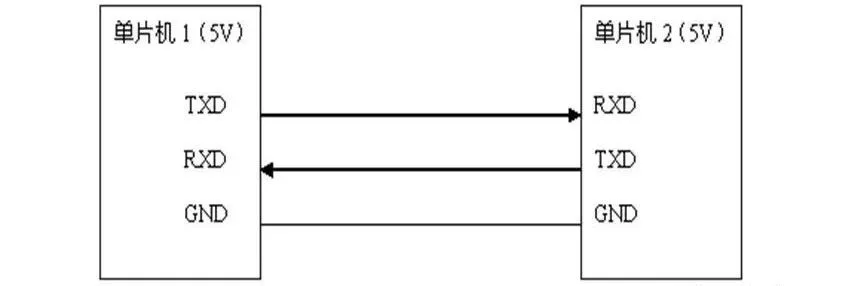
In embedded systems, on-board communication interfaces refer to the communication pathways or buses used to interconnect various integrated circuits with other peripheral devices.
UART, I2C, RS485, etc., are commonly used, and their understandings may be ambiguous. This article organizes them.
UART (Universal Asynchronous Receiver-Transmitter)
UART port refers to a physical interface form (hardware).
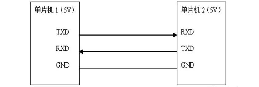
UART is an asynchronous, full-duplex serial bus. It is much more complex than synchronous serial ports. It has two wires: one TXD for transmission and one RXD for reception.
UART's serial data transmission does not require the use of clock signals for synchronous transmission, but relies on predefined configurations between the transmitting and receiving devices.
For both the transmitting and receiving devices, their serial communication configurations should be set to be exactly the same.

● Start bit: Indicates the start of data transmission, with a logic level of "0".
● Data bits: Possible values are 5, 6, 7, 8, 9, representing the transmission of these bits of data. Generally, the value is set to 8, as one ASCII character has 8 bits.
● Parity bit: Used by the receiver to verify the received data. It checks whether the number of "1" bits is even (even parity) or odd (odd parity), thereby verifying the correctness of data transmission. This bit is optional.
● Stop bit: Indicates the end of a frame of data. Its logic level is "1".
● Baud rate: The rate of serial communication, represented by the number of effective bits (bits) transmitted per unit time, with the unit being bits per second (bps).
If a general-purpose IO port is used to simulate a UART bus, one input port and one output port are required.
I2C bus
The I2C bus is a synchronous, half-duplex bidirectional two-wire serial bus. It consists of two buses: the serial clock line SCL and the serial data line SDA.
SCL line - responsible for generating synchronous clock pulses.
SDA line - responsible for transmitting serial data between devices.
This bus can connect multiple I2C devices to the system. Devices connected to the I2C bus can function as either a master or a slave device.
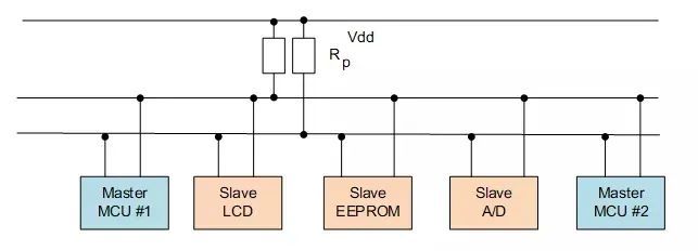
The master device controls the communication, initializes data transmission, sends data, and generates the required synchronous clock pulses. The slave device waits for commands from the master device and responds to the received commands.
Both the master and slave devices can function as sending or receiving devices. Regardless of whether the master device is acting as a sending or receiving device, the synchronous clock signal can only be generated by the master device.
If a general-purpose IO port is used to simulate the I2C bus and achieve bidirectional transmission, one input/output port (SDA) and one output port (SCL) are required.
SPI serial peripheral interface
The SPI bus is a synchronous, full-duplex bidirectional 4-wire serial interface bus. It is a system consisting of a single master device and multiple slave devices.
In the system, as long as only one master device is active at any given time, multiple SPI master devices can exist. It is commonly used for communication between AD converters, EEPROM, FLASH, real-time clocks, digital signal processors, and digital signal decoders.
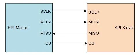
To achieve communication, SPI has four signal lines, which are:
● Master Out Slave In (MOSI): a signal line for transmitting data from the master device to the slave device, also known as Slave Input/Slave Data In (SI/SDI).
● Master In Slave Out (MISO): a signal line for transmitting data from the slave device to the master device, also known as Slave Output/Slave Data Out (SO/SDO).
● Serial Clock (SCLK): a signal line for transmitting clock signals.
● Slave Select (SS): a signal line for selecting the slave device, which is active low.
The timing mode of SPI is determined by the phase relationship between Clock Polarity (CPOL) and Clock Phase (CPHA).
CPOL indicates the initial state of the clock signal, where CPOL=0 indicates the initial state of the clock signal is low, and CPOL=1 indicates the initial state of the clock signal is high.
CPHA indicates which clock edge to sample data at, where CPHA=0 indicates to sample data at the first clock transition edge, and CPHA=1 indicates to sample data at the second clock transition edge.
There are four timing modes based on different combinations of CPOL and CPHA:
● CPOL=0, CPHA=0
● CPOL=0, CPHA=1
● CPOL=1, CPHA=0
●CPOL=1, CPHA=1
Comparison of UART, SPI, and I2C
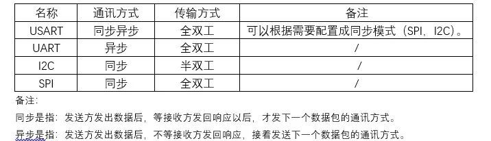
●I2C has fewer lines and is more powerful than UART and SPI, but it is also technically more complex. This is because I2C requires bidirectional IO support and uses pull-up resistors, which have weaker anti-interference capabilities. It is generally used for communication between chips on the same board and less for long-distance communication.
●SPI implementation is simpler, while UART requires a fixed baud rate, meaning the interval between two bits must be equal. SPI, however, does not matter because it is a clocked protocol.
●I2C is slightly slower than SPI and has a slightly more complex protocol, but it also requires fewer wires than the standard SPI.
●UART can transmit 5/6/7/8 bits per frame, while I2C must transmit 8 bits. Both I2C and SPI start transmitting from the highest bit.
●SPI uses a chip select signal to select the slave device, while I2C uses an address to select the slave device.
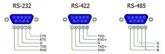
RS232 serial communication
There are two transmission lines and one ground line. The voltage levels are negative logic:
-3V to -15V for logic "1", and +3V to +15V for logic "0".
RS-232 serial communication has a transmission distance of about 15 meters. It can achieve bidirectional transmission, full-duplex communication, and a transmission rate of up to 20kbps.
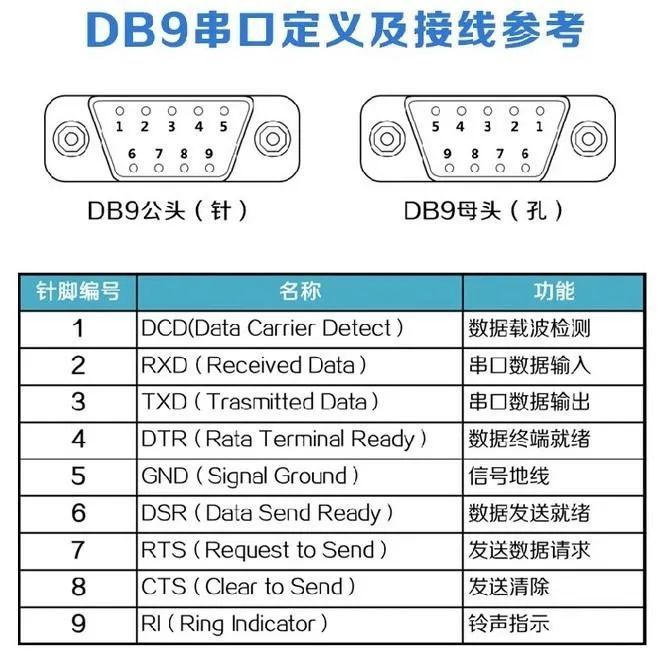
The following figure shows the definitions of DB9 male and female connectors. The most commonly used signals are RXD, TXD, and GND.
TTL and RS-232 conversion
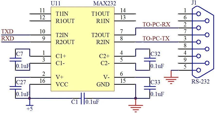
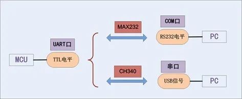
The interface of a microcontroller is generally TTL level. If it is connected to a peripheral device with 232 level, a TTL to RS232 conversion module is required. As shown below, the MAX232 chip can be used for conversion.
RS422 serial communication
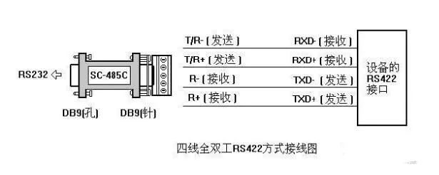
RS-422 has four signal lines: two for transmitting, two for receiving, and one for grounding, and it supports full-duplex communication.
It has one master device and the rest are slave devices. Slave devices cannot communicate with each other, so RS-422 supports point-to-multipoint bidirectional communication.
RS485 serial communication
RS-485 uses balanced transmission and differential reception, thus it has the ability to suppress common-mode interference.
It uses two-wire half-duplex transmission with a maximum speed of 10Mb/s. The logic level is determined by the voltage difference between the two wires, which improves anti-interference capability and allows for long transmission distances (from tens of meters to thousands of meters).
+2V to +6V represents logic "1", and -2V to -6V represents logic "0".
Converting TTL to RS-485 is common, such as with MAX485. The reference circuit is as follows
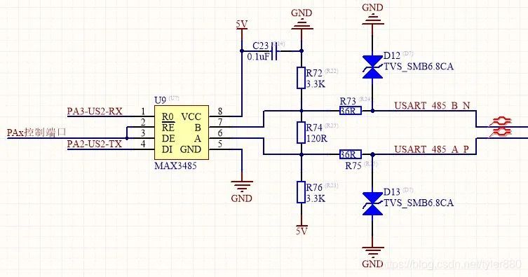
RE pin: receiver output enable (active low).
DE pin: transmitter output enable (active high). It can be directly controlled through the IO port of the MCU.
TTL
The serial port mentioned in embedded systems generally refers to the UART port. It has 4 pins (Vcc, GND, RX, TX) and uses TTL voltage levels.
The COM port in a PC, also known as the serial communication port, is referred to as the serial port. It has 9 pins and uses RS232 voltage levels.
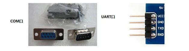
The serial port and COM port refer to physical interface types (hardware). TTL, RS-232, and RS-485 refer to voltage level standards (electrical signals).
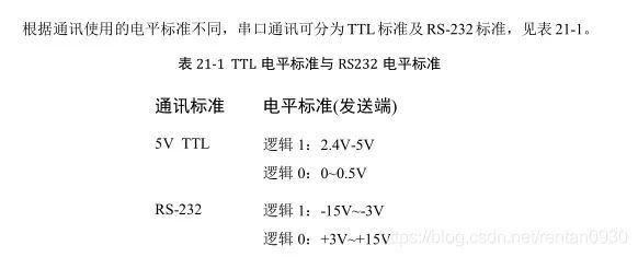
The schematic diagram of communication between a microcontroller and a PC is as follows:
CAN bus
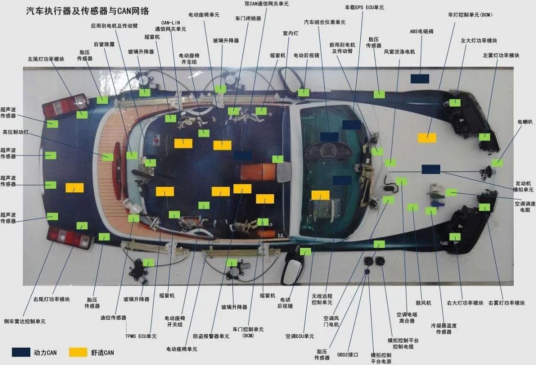
CAN is an abbreviation for Controller Area Network, which is a serial communication network capable of achieving distributed real-time control. The CAN bus has complex and intelligent functions and is mainly used for automotive communication.
The CAN bus network is mainly connected to CAN_H and CAN_L, and each node achieves serial differential transmission of signals through these two lines. To avoid signal reflection and interference, a 120 ohm terminating resistor is also required between CAN_H and CAN_L.
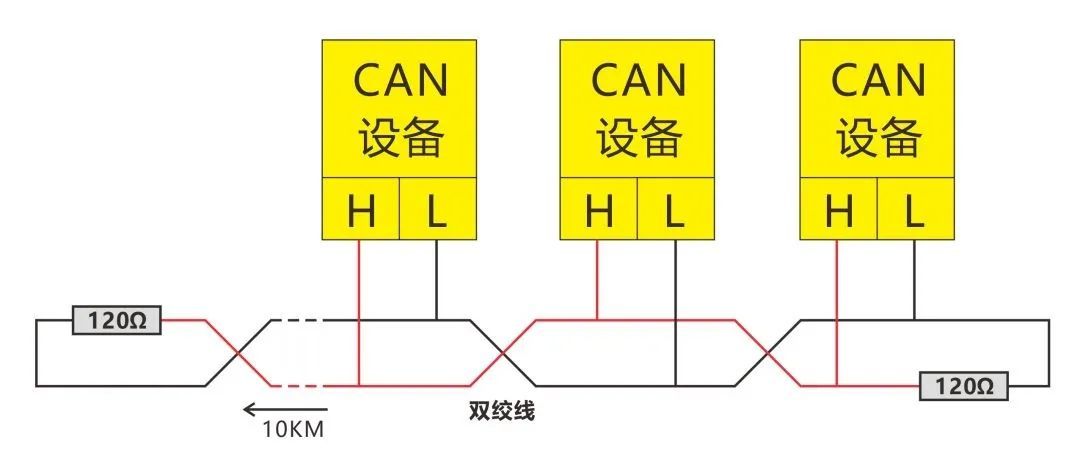
Each device can act as either a master or a slave. The communication distance of the CAN bus can reach up to 10 kilometers (at a rate of less than 5Kbps), and the speed can reach up to 1Mbps (when the communication distance is less than 40 meters).
CAN voltage level logic
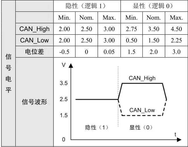
The CAN bus adopts the "wire-AND" rule for bus arbitration, where 1&0 equals 0. Therefore, 0 is called dominant and 1 is called recessive.
From the perspective of electrical potential, high potential is defined as 0 and low potential as 1. When signals are transmitted, they actually exhibit high potential, which appears as if 0 covers 1 from a phenomenological perspective. Therefore, 0 is called dominant and 1 is called recessive.
USB communication serial bus
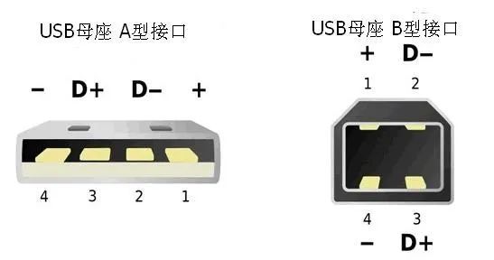
A USB interface has at least four wires, two of which are data lines, and all USB data transmission is completed through these two lines. Its communication is much more complex than serial communication.
The two data lines use differential transmission, which means that two data lines are required to transmit one bit, thus it is half-duplex communication, where only sending or receiving can occur at the same time.
According to USB specifications, if the voltage level remains unchanged, it represents logic 1; if the voltage level changes, it represents logic 0.
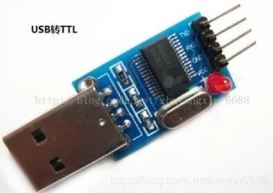
USB to TTL conversion
Generally, USB to serial port conversion uses the CH340G chip.
Serial port communication is simpler than USB because it does not require a protocol.
SD card
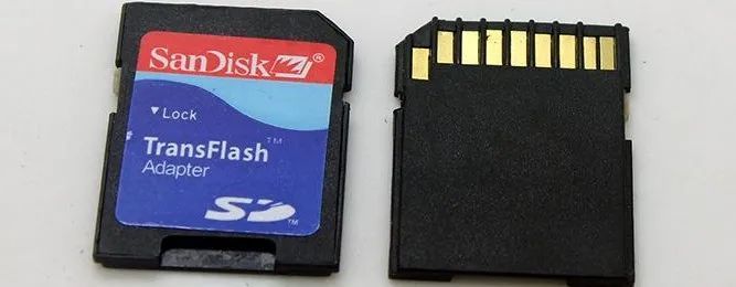
An SD card is a type of memory card that can be used as an internal storage card in mobile phones.
In embedded systems, there are two modes for communication between a microcontroller and an SD card:
● SPI bus communication mode
● SD bus communication mode
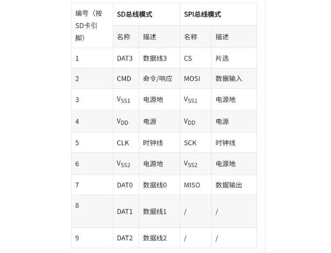
It is worth noting that the SD bus mode has four data lines; the SPI bus mode only has one data line (MOSI and MISO cannot read or write data simultaneously);
In embedded systems, when communicating between a microcontroller and an SD card, using the SD bus mode is several times faster than the SPI bus mode.
1-WIRE bus
1-Wire, introduced by the American company Dallas, is an asynchronous half-duplex serial transmission. It uses a single signal line for both clock and data transmission, and the data transmission is bidirectional.
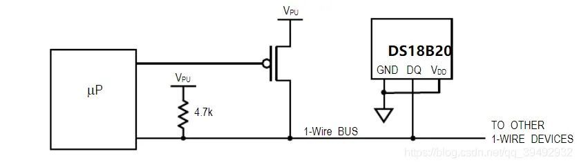
The data transmission rate of the 1-Wire bus is generally 16.3 Kbit/s, with a maximum of 142 Kbit/s, and usually the transmission rate is below 100 Kbit/s.
The 1-Wire port is an open-drain or tri-state port, so a pull-up resistor Rp is generally required, typically chosen to be 5K~10KΩ.
It is mainly used in: identification of print cartridges or medical consumables; identification and authentication of printed circuit boards, accessories, and peripherals.
Direct Memory Access (DMA)
DMA is a hardware module within the STM32, independent of the CPU, that performs data transmission between peripherals and memory, freeing up the CPU and greatly improving its efficiency.
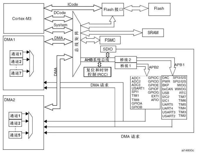
It can access peripherals and memory at high speed, without being controlled by the CPU, and it is bidirectional communication. Therefore, using DMA can greatly increase the data transmission speed, which is also a highlight of the ARM architecture - DMA bus control.
DMA corresponds to a highway, with dedicated and high-speed characteristics. If DMA is not used, the goal can still be achieved, but the time to achieve it is longer.
Ethernet
Ethernet is currently the most widely used local area network technology. As we all know, Ethernet interfaces can be divided into protocol layers and physical layers.
The protocol layer is implemented by a single module called MAC (Media Access Layer) controller.
The physical layer consists of two parts: PHY (Physical Layer) and the transmitter.
Currently, many motherboards' southbridge chips already include Ethernet MAC control functionality, but they do not provide a physical layer interface. Therefore, an external PHY chip is required to provide an Ethernet access channel.
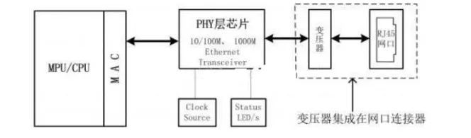
The function of a network transformer is:
● Coupling differential signals for stronger anti-interference capability
● The transformer isolates different voltage levels of different devices at the network cable end, isolating DC signals
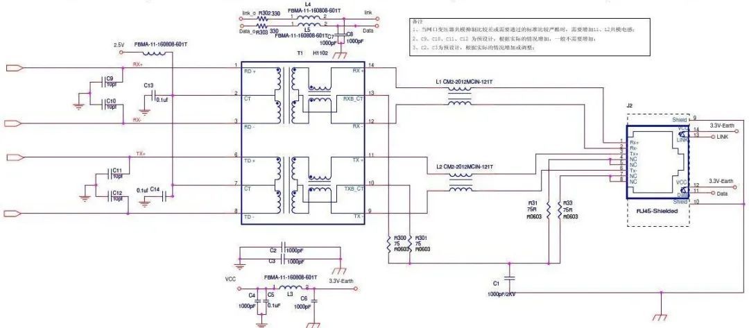
The reference circuit for the Ethernet interface is shown in the figure below.


Leave a Reply