
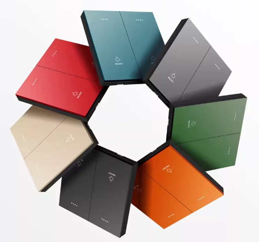
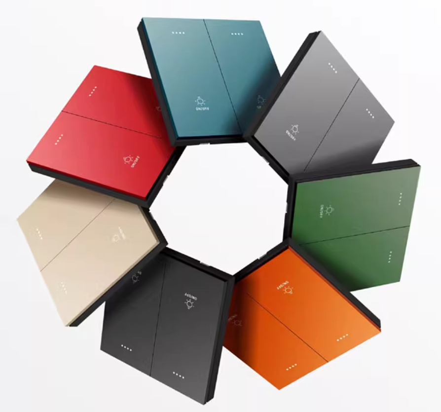
Product Model: Q06V4.3
Product Name: Q Series Intelligent Scene Panel Switch
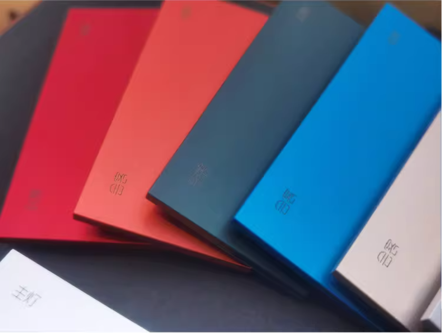
Appearance Material: Metal Aluminum Alloy (CNC Process, Anodized Sandblasting)
Color Selection: Vitality Orange/Moonlight Silver/Champagne Gold/Ivory White/Graphite Black/China Red/Emerald/Sky Blue/Elegant Grey/Gemstone Blue
Product Specification:
| Name | Remarks |
| Q06+3 (with 3 relays) RS485 Version | Simultaneously compatible with Modbus protocol, custom protocol |
| Q06+2 (with 2 relays) RS485 version | Simultaneously compatible with Modbus protocol, custom protocol |
| Q06+1 (with 1 relay) RS485 version | Simultaneously compatible with Modbus protocol, custom protocol |
| Q06+0 scene switch (without relay) RS485 version | Simultaneously compatible with Modbus protocol, custom protocol |
| Q4+2 (with 2 relays) RS485 version | Simultaneously compatible with Modbus protocol, custom protocol |
| Q4+1 (with 2 relays) RS485 version | BI_23] Q04+0 scene switch (without relay) RS485 version |
| Q04+0 scene switch (without relay) RS485 version | Simultaneously compatible with Modbus protocol and custom protocol |
| Q06+3 (with 3 relays) LoraMesh version | LoraMesh wireless communication, compatible with Modbus protocol and custom protocol |
| Q06+2 (with 2 relays)LoraMesh version | LoraMesh wireless communication, compatible with Modbus protocol and custom protocol |
| Q06+1 (with 1 relay)LoraMesh version | LoraMesh wireless communication, compatible with Modbus protocol and custom protocol |
| Q06+0 scene switch (without relay)LoraMesh version | LoraMesh wireless communication, compatible with Modbus protocol and custom protocol |
| Q4+2 (with 2 relays)LoraMesh version | LoraMesh wireless communication, compatible with Modbus protocol and custom protocol |
| Q4+1 (with 2 relays)LoraMesh version | LoraMesh wireless communication, compatible with Modbus protocol and custom protocol |
| Q04+0 scene switch (without relay)LoraMesh version | LoraMesh wireless communication, compatible with Modbus protocol and custom protocol |
| LoraMeshgateway | LoraMesh transmitter receiver |
Note:
1. Lora Mesh has a long communication distance and strong diffraction ability
2. Detach from point-to-point, self-organizing network, and self relay.
3. Fast networking speed, networking immediately upon power on.
1, Product Overview
This product is a multifunctional intelligent scene control panel, which integratesWired RS485 bus communication, ZgbMesh/LoraMesh wireless networking, Custom scene linkageIntegrated, suitable for household, commercial, and industrial scenarios. Supportbutton vibration feedback, multi protocol compatibility, weak/strong dual power supply mode, It has high stability, low power consumption, and strong anti-interference ability, meeting the intelligent control requirements in complex environments.
II. Technical Parameters
| Project | Parameters/Functions |
|---|---|
| Physical Specifications | Size 86 × 86 × 40mm, embedded depth 28mm, weight 100-160g (depending on the number of relays) |
| Power Supply Method | Weak Current DC12-24V (standard, reverse protection) Strong Current AC85-265V (optional, overload/short circuit/overcurrent protection) |
| Bus Communication | Standard RS485 (baud rate 9600 8 N 1, stable and reliable) Optional ZgbMesh 2nd Generation/LoraMesh Wireless Communication (decentralized networking) |
| Load Capacity | Resistive Load ≤ 1800W, Inductive Load ≤ 500W |
| Operating Temperature | -10 ℃~50 ℃ |
| Button Features | Metal Button (Supports Vibration Feedback, Can Be Closed) Support On/Off/Click/Flip/Double Click/Long Press/Delay On/Off Self Defined Function |
| Relay Type | 16A Self Holding Double Coil Relay (No Current Holding, Low Power Consumption) |
| Control Protocol | Input/Output Protocol Fully Customizable, Compatible with Modbus Protocol |
III. Core Function Highlights
1, Advanced metal matte texture, comfortable and delicate touch, crisp feedback when pressed.
2. The button supports vibration feedback for better tactile feedback and can be turned off.
3. Adopt high-power non adhesive double coil high-quality relay.
4. Self holding relays do not require current to maintain their state, resulting in lower power consumption and greater energy efficiency. 5. Weak current plug-in terminal design, quick and convenient installation.
5. Weak current plug-in terminal design, quick and convenient installation.
6. Outstanding reaction speed, anti-interference ability, and stability.
7. Remote control, on/off at any time (needs to be used with a smart host)
8. It can not only be a switch, but also a scene panel, with multiple intelligent accessories to achieve personalized scene control.
9. Fearless of network disconnection, able to control even in a network free state.
10. Supports running away from the host and sending custom scenario commands
11. Supports connecting to a third-party bus control system and achieving bidirectional communication.
12. The buttons inside this switch support jog, double-click, and long press to control any relay inside the switch
13, This switch button supports tapping, double clicking, and long pressing to be associated with other switch buttons.
14. Supports separate control of background lights.
15. Supports full customization of input control protocols and output control protocols.
16. Supports delayed closing and delayed opening.
17. Supports children's button locking function.
18. The button supports customized text marking laser engraving and cutting.
19. Supports ZgbMesh 2 wireless communication, decentralized design, and can still network communication in case of host failure.
20. Supports weak current 12-24V power supply, with reverse connection protection for weak current.
21. Supports strong current 85-265V AC power supply, with short circuit, overload, over temperature and over-current protection.
IV. Installation and Wiring Instructions
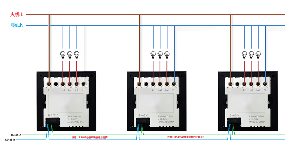
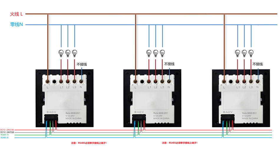
1. Wiring Terminal Instructions
- Weak Current Terminal: DC12-24V input (red positive/black negative).
- Strong current terminal: AC85-265V input (live wire L/neutral wire N).
- Load output: Connected to relay control circuit (L1/L2/L3...).
AC220V power supply wiring diagram:
DC12~24V power supply wiring diagram:
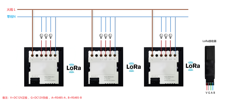
LoraMesh version wiring diagram:
Attention: About 20 meters indoors, can pass through 2-3 walls, and within 100 meters outdoors!
2. Installation steps
- After turning off the power, insert the panel into the standard 86 bottom box and fix it with screws.
- Connect weak or strong power sources as needed and connect load devices.
- Connect to the intelligent control system via RS485 or wireless protocol (gateway needs to be configured).
⚠️ Attention
- Strong current wiring should be operated by professional electricians to ensure power-off construction.
- Avoid direct contact between metal panels and strong electrical cables.
V. Communication Protocol and Debugging Tools
1. Private Protocol
Default Address: XX XX XX XX(Based on the actual switch label)
1. Bus Baud Rate and Address
Baud Rate:9600 (Power on feedback 5 byte address, 1 byte Modbus address, 2 byte Mesh networking address)
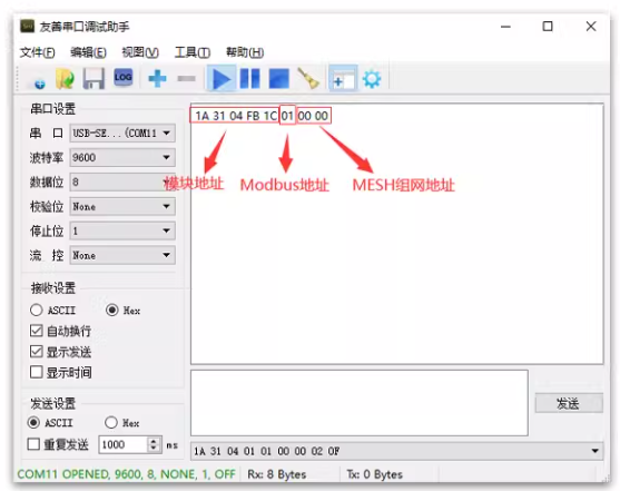
Change Address:Send XX XX XX XX (old address) F8 E7 D6 (fixed) yy yy yy yy yy yy (new address)
Example:1A 13 24 56 91 F8 E7 D6 1A 33 57 26 81
Change the old address 1A13 24 56 91 to the new address 1A 33 57 26 81
2. Group control address
Address wildcard:FF
Broadcast address:FF FF FF FF FF
FF can be at any position in the five byte address of XX XX XX XX XX XX.
Modify address branching to achieve group control and scenario control through the configuration of addresses and wildcard characters.
Example:
Sending XX XX XX FF can control a module with 254 addresses, including XX XX XX 00- XX XX XX XX XX FE.
Sending XX FF FF XX XX can control XX 00 XX XX - XX FE XX XX XX XX XX, with a total of 254 addresses*A module with 254 addresses
sends FF FF XX FF XX, which can control 00 00 XX 00 XX - FE FE XX FE XX a total of 254 * 254 *A module with 254 addresses
sends FF FF XX, which can control 00 00 00 XX - FE FE FE XX a total of 254 * 254 *254a module with 254 addresses
52] Channels: 00 01 02 03 04 05 (corresponding to keys 1-6) 08 09 0A (corresponding to the first to third columns of the backlight)
3. Single control instruction
XX XX XX XX XX (address) 00 (fixed) 00 (number of channels) 02 (function) 0F
Route: 00 01 02 03 04 05 (corresponding to keys 1-6) 08 09 0A (corresponding to the first to third columns of the backlight)
Function:02 Status Flip 01 On 00 Off 03 Jogging
Example:XX XX XX XX XX 00 00 02 0F 1st switch flip

4. Multiple overall operation instructions
Switch: XX XX XX XX XX (address) 01/02 (fully open/closed) 77 88 0F
Backlight: XX XX XX XX XX (address) 10/20 (fully open/closed) 77 88 0F
Overall: XX XX XX XX XX (address) 30/40 (fully open/closed) 77 88 0F (overall representing backlight and switch)
Example: XX XX XX XX XX 01 77 88 0F switch all open
5. Composite operation instruction (1 control instruction controls any function of the switch)
XX XX XX XX (Address) CA (Fixed) 00 (Number of Channels) 02 (Function) 01 (Number of Channels) 02 (Function) 0A (Number of Channels) 02 (Function) 0F
Number of channels:00 01 02 03 04 05 corresponds to buttons 1-6 08 09 0A corresponds to the first to third columns of the backlight
Function: 02 on/off 01 on 00 off 03 jog 04 maintain original state
Example: XX XX XX XX XX CA 00 01 00 02 03 0A 01 0F Press button 1 on, button 2 off, button 3 flip button 4 jog, backlight third column on
6, Status query instruction
sends XX XX XX XX (address) 86 86 86 0F
feedback XX XX XX XX (address) 00 00 00 00 01 01 (switch 1-6 status) 00 00 00 (fixed) 01 01 (backlight first to third column status) 00 00 00 00 00 00 (fixed) 0F
status: 00 off 01 on
Example:
sends: XX XX xX XX XX XX 86 0F
feedback: XXXXXXXXXX 00 00 00 01 01 00 00 01 01 00 01 00 00 00 00F
Switch 1-6 states are off, off, on, and on, while the first to third columns of the backlight are on and off.
7. Stair protocol instruction
XX XX XX XX XX XX (address) CB (function) 00 03 (time interval for sequentially opening) 00 04 (time interval for keeping all open)
00 05 (time interval for sequentially closing) 0F
Time interval for sequentially opening, range 00 00 00 FF FF, time unit 0.1 second
The time to maintain all open states, ranging from 00 00 to FF FF, with a time unit of 0.1 seconds.
The time interval for sequentially closing, ranging from 00 to FF FF, with a time unit of 0.1 seconds.
Function:The CB switch and backlight are turned on in the forward direction in sequence; The CC switch and backlight are turned on in reverse order; The CD switches are sequentially turned on in the forward direction; The CE switch is turned on in reverse order; The CF backlight is turned on in a forward direction in sequence; C0 backlight turns on in reverse order
Example:XX XX XX XX XX CB 00 03 00 04 00 05 0F Switch and backlight turn on in forward order, with a time interval of 0.3 seconds between turns on; Keep all open for 0.4 seconds; The time interval for sequentially closing is 0.5 seconds
8. Custom staircase protocol
XX XX XX XX XX XX (address) D3 (fixed) 00 01 (delay time interval) 01 (01 on/00 off/02 flip) 01 (01 forward/
11 reverse) 01 (01 switch/11 backlight/02 overall) 0F
Delay time interval, range 0000-FFFF, time unit is 0.1 seconds
Example:XX XX XX XX D3 00 05 01 01 11 0F Backlight is sequentially turned on in the forward direction, with a delay time interval of 0.5 seconds when turned on
9. Correspondence between configuration buttons and outputs
Single switch single output:XX XX XX XX XX (address) BB 00 (fixed) 00 (number of channels) F1 (F1 long press/F2 single click/F3 double click) CA (fixed) 02 (number of output channels) 02 (output status 00 off/01 on/02 on/03 jog) 0F
Example:XX XX XX XX BB 00 03 F1 CA 04 0F
(key 4 long press to switch on/off output switch 5)
Single switch multi output:XX XX XX XX (address) BB 00 (fixed) 00 (number of channels) F1 (F1 long press/F2 single click/F3 double click) CA (fixed) 00 (number of output channels 1) 02 (switch) 01 (number of output channels 2) 01 (only on) 02 (number of output channels 3) 03 (jog) 0F
Example:XX XX XX XX XX BB 00 00 F1 CA 00 02 01 02 02 02 0F
(Button 1 is associated and matched with output switches 1, 2, and 3)
Delete configuration:XX XX XX XX XX (Address) BB 00 (Fixed) 00 (Number of Channels) F1/F2/F3 EE 0F
Example: XX XX XX XX BB 00 02 F1 EE 0F
(Delete the configuration of button 3 F1)
Route: 00 01 02 03 04 05 corresponds to keys 1-6 08 09 0A corresponds to the first to third columns of the backlight
Number of output channels:00 01 02 03 04 05 corresponds to outputs 1-6
10. Press the button to send custom bus data commands
to configure:XX XX XX XX (Address) B8 00 (Fixed) 00 (Number of Channels) E1 (E1 Relay Connected/E2 Relay Disconnected/E3 Single Click/E4 Double Click/E5 Long Press) 01 (Storage) YY YY YY YY YY YY YY YY YY YY YY YY YY (Custom Bus Data hex) 0F
This custom protocol can be used to control bus controlled devices. When the key input status is on/off, it sends custom bus data y γ YY YY YY YY YY YY YY YY YY YY YY YY. Custom data is less than 32 bytes
Number of routes:00 01 02 03 04 05 corresponds to keys 1-6
Storage:01-06 represents the 1st to 6th storage, supporting the storage of a total of 6 instructions
Example 1:XX XX XX XX XX BB 00 02 E3 0155 12 35 03 01 FC 4A0F storage 1: When key 3 is clicked
Send curtain bus data 55 12 35 03 01 FC 4A, open the curtains
Example 2:XX XX XX XX XX BB 00 02 E4 0255 12 35 03 01 FC 4A0F storage 2: When double clicking button 3,
Send curtain bus data 55 12 35 0301FC4A, open the curtains
Configure bus data transmission interval time:XX XX XX XX XX (Address) BB D1 (Fixed) 00 08 (Interval) 0F
Set the bus data transmission interval time based on the performance of the controlled product, ranging from 00 to FF FF, with a unit of 50 milliseconds and an interval time of 8 * 50=400 milliseconds
Example:The interval between sending each bus data on XX XX XX XX BB D1 00 02 0F is 100 milliseconds
Delete configuration:XX XX XX XX XX (Address) BB 00 (Fixed) 00 (Number of Channels) E1/E2/E3/E4/E5 EE 0F
Number of routes:00 01 02 03 04 05 corresponds to keys 1-6
Example:XX XX XX XX BB 00 03 E1 EE 0F Delete button 4 configuration
11. Lock button command
Lock button, fully open switch: XX XX XX XX XX (address) EC 00 0F FF 0F
Lock button, fully closed switch: XX XX XX XX XX (address) EC 00 00 00 0F
12. Unlock button command
Unlock button, fully open switch: XX XX XX XX XX (address) EC 01 0F FF 0F
Unlock button, fully closed switch: XX XX XX XX XX (address) EC 01 00 00 0F
13. Delay switch configuration instruction
XX XX XX XX XX (address) 9F (fixed) 01 (number of routes) 01 (time, corresponding to 1-255 seconds for 01-FF) 0F
Number of routes:00 01 02 03 04 05 corresponds to keys 1-6 08 09 0A corresponds to the first to third columns of the backlight
Example:
①XX XX XX XX XX 9F 01 06 0F
②XX XX XX XX XX BB 00 01 F2 CA 01 03 0F
Switch 2 will turn off after a delay of 6 seconds.
14. Jogging Mode Switching Protocol
XX XX XX XX XX (Address) 9D 00 00 0F Open and then delay close mode
XX XX XX XX XX (Address) 9D 00 01 0F Close and Delay Open Mode
15. Power on initial state configuration instruction
XX XX XX XX (Address) EA (Fixed) 00 (1st Road) 01 (On) 01 (2nd Road) 00 (Off) 02 (3rd Road) 01 (On) .... 0A (third column of backlight) 01 (on) 0F
Every 2 bytes form 1 group, set the initial state of the switch/backlight, 01 on/00 off
Number of routes:00 01 02 03 04 05 corresponds to keys 1-6
08 09 0A corresponds to the first to third columns of backlight
The default initial state for power on is off
Example:When XX XX XX EA 00 01 00 02 01 0A 01 0B 01 0F is initially powered on, the first circuit is turned on, the second circuit is turned off, the third circuit is turned on, and the third column of indicator lights is turned on.
16. Restore switch mode initial configuration
XX XX XX XX XX (Address) BB EE EE EE EE OF Delete all configuration data
Waiting for feedback (about 4-6 seconds): After BC BC
Send XX XX XX XX XX (address) BB D2 00 02 0F again
Example:Send XX XX XX XX BB EE EE EE EE 0F
Waiting for feedback (about 4-6 seconds): BCBC
Send XX XX XX XX BB D2 00 02 0F again to delete all data and restore the initial configuration
17. Vibration Open and Close Protocol
5-byte address+2A 2B 01 00 0F (the third to last digit represents vibration)
Activate vibration:5-byte address+2A 2B 01 00 0F
Turn off vibration:5-byte address+2A 2B 00 00 0F
18. Extreme Scenario Protocol (New)
① Protocol setting scenario:5-byte address+69 11 96 (fixed) 00 (scene location) 01 00 01 00 01 00 01 00 00 01 00 01 00 00 (values output from channels 1-16) 0F
② Trigger scenario:5-byte address+69 12 96 (fixed) 00 (scene location) 0F
③ Add the current output value to the one click scene:5-byte address+69 13 96 (fixed) 00 (scene location) 0F
④ Clear Scene:5-byte address+69 14 96 (fixed) 00 (scene location) 0F
Scene location: 00-FF supports 256 high-speed scenes
Note:
1. Instantly complete scene mode execution, with the same operational experience as KNX bus
2. Offline execution of scenarios, network disconnection, and host downtime do not affect usage.
3. The intelligent lighting module and intelligent dimming module are compatible with high-speed scenes.
4. Whole house intelligent lighting intelligent dimming, debugging optimization, and overall purchase provide pre configured or fast automated debugging documents, allowing ordinary people to debug smart home scenes.
5. Complete the synchronized upgrade of Q06V4.1, Q08V4.1, Q04V4.1, HKD60SV1.3, PD25V1.3, PD25BV1.3, and BP600AV1.3
In order to help everyone better debug the switch, our Geshe Debugging Assistant has provided quick debugging instructions for everyone. You only need to click with a fool to experience all the functions of the switch.
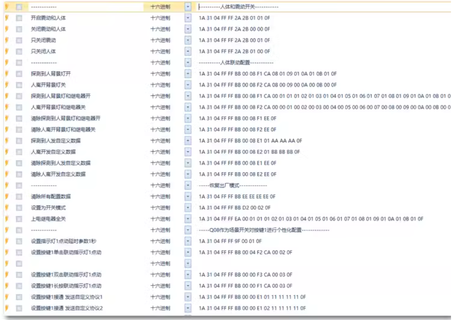
Gesi Debugging Elf Download:
Q06/Q08 series switch quick debugging instructions Gesi debugging wizard database download:
2. MODBUS communication protocol
Read register 03, write a single register 06, write multiple registers 10
| Serial number | Name | Read/Write | register address decimal | register address hexadecimal | Value | meaning |
| 1 | Address | Read/Write | 0001 | 00 01 | 00 02 (Change address to 2) | Address Range 01-FE |
| 2 | Switching baud rate | Read/Write | 0002 | 00 02 | 00 06 (modified to 9600 baud rate) | 00 00 to 115200 00 01 corresponds to 76800 00 02 corresponds to 57600 00 03 corresponds to 38400 00 04 corresponds to 19200 00 05 corresponds to 14400 00 06 corresponds to 9600 00 07 corresponds to 4800 00 08 corresponds to 2400 00 09 corresponds to 1200 |
| 3 | Switch 1 | Read/Write | 1001 | 03 E9 | 00 01 (on) | 00 00 off 00 01 Open 00 02 Flip 00 03 jog |
| 4 | Switch 2 | Read/Write | 1002 | 03 EA | 00 00 (off) | 00 00 off 00 01 Open 00 02 Flip 00 03 jog |
| 5 | Switch 3 | Read/Write | 1003 | 03 EB | 00 02 (Flip) | 00 00 off 00 01 Open 00 02 Flip 00 03 jog |
| 6 | Indicator light 1 | Read/Write | 1004 | 03 EC | 01 (on) | 00 00 off 00 01 Open 00 02 Flip 00 03 jog |
| 7 | Indicator light 2 | Read/Write | 1005 | 03 ED | 00 00 (off) | 00 00 off 00 01 Open 00 02 Flip 00 03 jog |
| 8 | Indicator light 3 | Read/Write | 1006 | 03 EE | 00 02 (Flip) | 00 00 off 00 01 Open 00 02 Flip 00 03 jog |
| 9 | Empty | Read/Write | 1007 | 03 EF | / | / |
| 10 | Empty | Read/Write | 1008 | 03 F0 | / | / |
| 11 | Background light 1 | Read/Write | 1009 | 03 F1 | 01 (on) | 00 00 off 00 01 Open 00 02 Flip 00 03 jog |
| 12 | Background light 2 | Read/Write | 1010 | 03 F2 | 00 00 (off) | 00 00 off 00 01 Open 00 02 Flip 00 03 jog |
| 13 | Background light 3 | Read/Write | 1011 | 03 F3 | 00 02 (Flip) | 00 00 00 Off 00 01 On 00 02 Flip 00 03 Jogging |
Protocol Example:
Read Single Register - Read Baud Rate
| Read Single | Address | Function Code | Register address | Read several registers | CRC check |
| Send | 01 | 03 | 00 02 | 00 01 | 25 CA |
Read multiple registers - Output 1, 2 status
| Read multiple | addresses | Function code | Start sender address | Read several registers | CRC check |
| Send | 01 | 03 | 03 E9 | 00 02 | 15 BB |
Write a single register - modify address to 02
| Write a single | address | Function code | Register address | Value | CRC check |
| Send | 01 | 06 | 00 01 | 00 02 | 59 CB |
Write multiple registers - Turn on 1-3 output, turn off 1-3 indicator light
| Write multiple | addresses | Function code | Start register address | Write several registers | Byte count | Data | CRC check |
| send | 01 | 10 | 03 E9 | 00 06 | 0C | 00 01 00 01 00 01 00 00 00 00 00 00 | 6C 55 |
CRC16 Verification Tool Download:
This tool is used to quickly calculate the CRC16 checksum value in MODBUS communication. Enter a hexadecimal data packet in the input box (every two characters represent one byte, and the number of characters must be even),Separate each byte with a spaceAfter clicking calculate, this calculator can calculate the hexadecimal checksum of the length of the input data packet.
In order to help everyone better debug the switch, we have provided quick debugging instructions using Modbus poll. You only need to click to experience all the Modbus functions of the switch.
6, Troubleshooting and Maintenance
| Problem | Solution |
|---|---|
| Button unresponsive | Check if the power supply is normal and restart the device. |
| Wireless connection failed | Confirm gateway is online, re pair device. |
| Relay does not operate | Check if the load exceeds the limit and if the wiring is secure. |
Maintenance Recommendations:
- Regularly clean the surface of the panel with a dry cloth to avoid liquid infiltration.
- Disconnect the power supply when not in use for a long time to avoid standby power consumption.
7, After sales service and support
- Warranty Period1.5 years (non human damage).
- Technical Support18801054468 (weekdays 9:00-18:00)
- Protocol OpenProvide SDK and API documentation, support third-party system development and integration.
Appendix: Examples of Application Scenarios
- Home Scenario
- One click "viewing mode": turn off the lights, lower the curtains, and turn on the projector.
- The entrance lights are turned off with a delay to avoid forgetting.
- Industrial Scene
- button controls the start and stop of the fan, with custom timing to reduce current surge.
- Business scenario
- Grouping and group control of mall lighting, remote management of energy-saving strategies.
Product Purchase:https://item.taobao.com/item.htm?ft=t&id=671086569988


Leave a Reply