
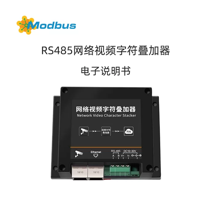
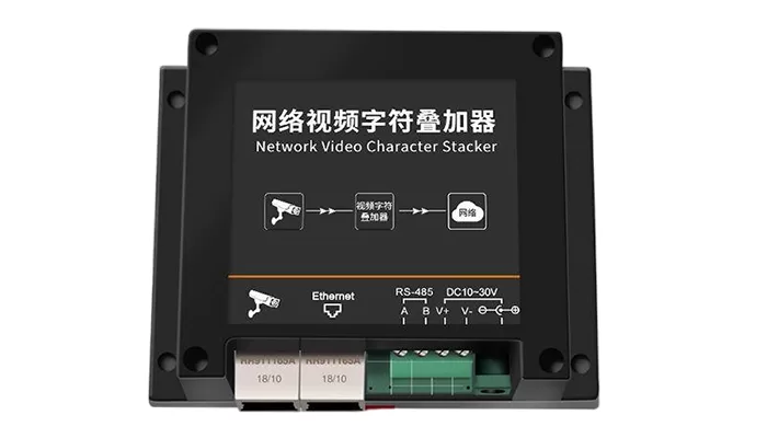
Product Overview
The network video character adder is a device developed by our company specifically for the market standard ModBus RTU communication mode 485 equipment, suitable for high-definition network cameras. Users can connect this product to a 485 device according to their actual needs, and after a simple configuration of the adder, the corresponding character information will be overlaid and displayed on the high-definition network camera video screen. The device adopts the standard ModBus RTU communication mode, matching all standard ModBus RTU devices on the market, and can be used for sensor overlay character information, computer room monitoring, intelligent agriculture, meteorological monitoring and other places.
The character superimposer can support the overlay of multiple cameras simultaneously. Each character adder can support up to 4 cameras and 16 standard ModBus RTU communication mode 485 devices simultaneously. The configuration software is simple and convenient, supports multiple data type settings, and register addresses can be offset for reading. The underlying protocol docking of the camera does not affect the original video signal, and the position of the overlaid information can be adjusted.
The device has a compact and beautiful appearance, occupies a small space, and has a simple and convenient installation method.
Features
■ The product adopts standard ModBus RTU communication, matching all standard ModBus RTU communication devices
■ The product can simultaneously process character information from multiple cameras, supporting up to 4 cameras overlapping
■ The product can connect to multiple 485 devices, up to 16 485 devices
■ Independent software configuration, powerful functions, simple interface, easy operation
■ Camera underlying protocol docking, does not affect the original video signal
■ Character display position is adjustable on the full display screen
■ Supports any Chinese, English, punctuation display (display quantity depends on the camera)
■ Camera displays real-time monitoring of on-site data changes
■ Supports DC10~30V wide voltage input
Main technical specifications
| Power supply | 10~30V DC |
| Power consumption | 1.5W (DC12V) |
| Input signal | 485 (ModBus RTU) |
| Output signal | RJ45 network port |
| Temperature and humidity resistance of transmitter components | -20 ℃~+70 ℃, 0% RH~95% RH non condensing |
| Data update time | 3s |
| Power supply range | DC10~30V |
| Baud rate | 2400~ 115200bps |
| Applicable cameras | All models of network cameras including Hikvision, Uniview, Dahua, Zhongwei Century, Tongwei, Huawei, Xinruishi, Tiandi Weiye, Xiongmai, etc. (other cameras need to be customized) |
Equipment installation instructions
Equipment List
One network video character superimposer
■ Certificate of conformity, warranty card, etc
One Ethernet cable
Installation method
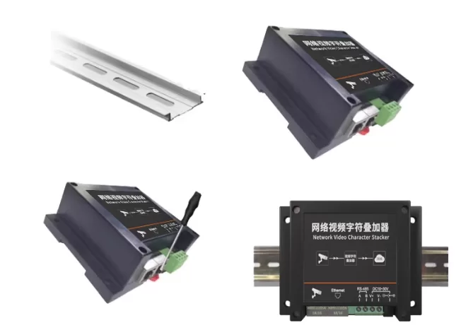
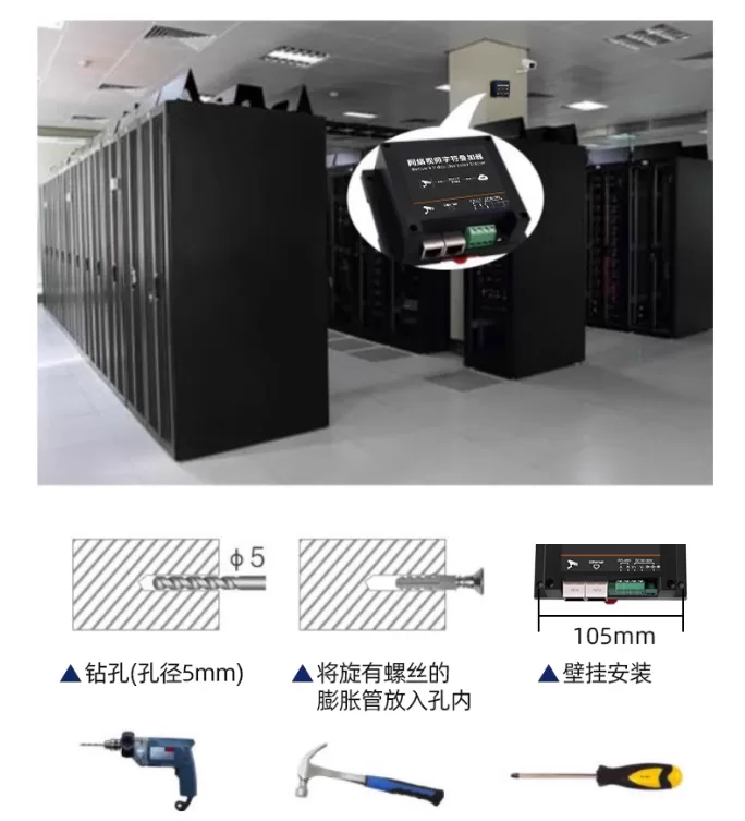
1. The equipment can be installed using standard 35 guide rails
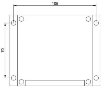
2. The device can also be wall mounted for installation
Wiring example
1. Connect the camera, character superimposer, and computer during configuration.
2. When using, place the character adder and camera in the same local area network.
Install and use configuration software
Network parameter reading and setting
Connect the computer and character adder to the same local area network.
After installing the configuration software, double-click to open the configuration software, click search, and the software will search for all character adder devices within the same local area network. Double click on the devices found. The device network information is displayed in the right-hand column. The method of obtaining IP can be modified according to user needs in the right-hand column. Attention: When changing to a solid-state IP, please set the IP to the same network segment as the computer or camera, and the IP address must not conflict.

Parameter acquisition and setting
1. Select the camera, and the number represents the camera parameters that need to be configured. Up to four cameras can be configured.
2. Fill in the required camera IP address in the camera address field, and fill in the camera port according to the actual situation. Hikvision defaults to 80, Uniview defaults to 1026, Zhongwei Century defaults to 34567, Dahua defaults to 80, both default to 80, Huawei defaults to 80, Xinrui Vision defaults to 80, Tiandi Weiye defaults to 80, and Xiongmai Head defaults to 8899. Fill in the username and password for the camera (Huawei cameras require a northbound username and password for some models; Xinrui Vision cameras must have a password set). The number of rows to be stacked can be selected based on the actual condition of the camera. If the device camera is a single line stacked camera, the number of rows should be set to 1. Choose the appropriate brand for the camera. The source port defaults to 0 and does not need to be modified.
Note:
1) Dahua and Huawei's cameras can only be stacked on top of each other and need to be configured on camera one. When the Hikvision camera needs to stack eight lines, select "Hikvision (Long Byte)" and only one camera can be stacked.
2) When the Hikvision camera needs to stack eight lines, select "Hikvision (Long Byte)" and only one camera can be stacked.
3) Due to the limitations of the cameras themselves, the cameras of Xiongmai and Tiandi Weiye only support stacking one line, and Xiongmai cameras are stacked at the channel name position.
4) Huawei O camera only supports overlaying 5 lines. If the overlay content exceeds 5 lines, the camera will overwrite the 6th and subsequent lines to the first 5 lines. It is not recommended for customers to use it on their own. Below
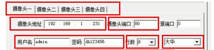
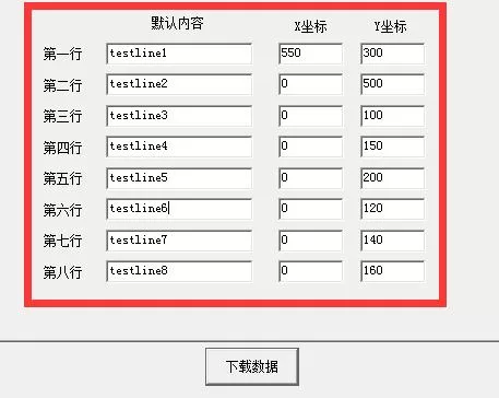
3.is an 8-line overlay of information (if it is a single channel camera, only the first line of information needs to be filled in). The default content filled in is the fixed display content of the camera. When receiving the content uploaded by the 485 device, this content will no longer be displayed. For example, the default content for area 1 of camera number 1 is filled in with "aaa". If the RS485 receiver of the character adder does not receive the content sent by the 485 device, the camera area 1 will continue to display "aaa". If the RS485 receiver of the character adder receives the content sent by the 485 device as "temperature: 18 ℃", the camera area 1 will display "temperature: 18 ℃" and "aaa" will no longer be displayed. (Note: Dahua's camera can only display numbers or letters in the first line, and Chinese characters are invalid. If you need to overlay fixed information or upload content through 485, you need to start from channel two.)
4.The display area position can be adjusted, and the value of the coordinate XY can be modified. After modification, click "Download". The "Information Prompt Area" in the bottom left corner will display "Download Successful" (note: this function applies to Hikvision cameras; the position of the Uniview camera needs to be set in the camera configuration; the display area of the first row of the Dahua camera is not adjustable, and the first row needs to be set in the camera configuration, while other rows can be adjusted; the position of the Zhongwei Century camera needs to be set in the camera configuration; for the same camera, the second row follows the first row, the fourth row follows the third row, and so on. If Huawei cameras need to display time, the default content of the first row should be filled in quotation marks.)$ {time@sys There is an English space after the colon 'YYYY-MM-DD}', and the rest of the information is overlaid starting from the second line. ) The default content supports up to 32 Chinese characters (some cameras do not support it).
1.Click on "485 Parameters" and then click on "Read". The page displays the 485 parameters uploaded by the device. Users can fill in and read the parameters of the 485 device according to their needs on this interface. After the user completes the modification, click on "Download". The information prompt area shows that the download is successful and the modification is complete.
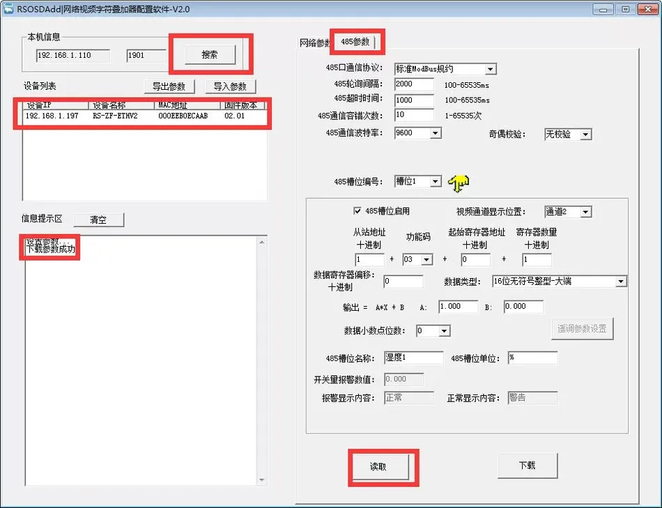
2.485 Communication Parameter Settings
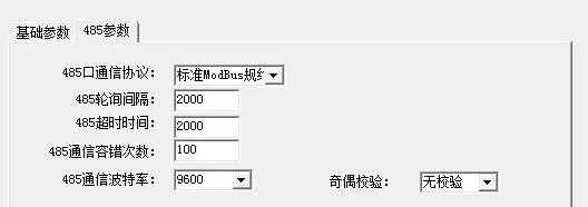
485 Port Communication Protocol: The character adder has two communication protocols to choose from. If the user uses the product to customize dust equipment for Renke, they can choose the internal protocol, while other products can choose the standard ModBus protocol.
485 Polling Interval:Device Polling Interval. Setting range: 100~65535 ms
485 Timeout time:Device timeout time setting. When the time exceeds the limit, it will automatically query the next device. Setting range: 100~65535 ms
485 Communication fault tolerance:After exceeding the communication limit, the character adder determines that the 485 device is offline. Setting range: 1~65535
485 Communication baud rate:485 device communication rate setting. 2400~115200 selectableParity check:Select parity check mode.
3.Device parameter upload setting
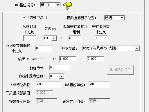
485 Slot number:is the slot number of the register that needs to be read by the 485 device.
485 Slot Enable:Each slot needs to be checked before it can be enabled. If it is not checked, the parameters set for the slot will not be enabled.Video Channel Display Position:The camera can display up to 4 channels, and in this position, select which channel to display the device's uploaded information on. Each channel can display up to 44 bytes (note: when a channel displays multiple slot information, each slot is separated by one byte. When the last slot information exceeds 64 bytes, the last slot information will no longer be displayed)
Slave address:Fill in the device address. Scope: 1-255.
Function code:Select the reading function code that the device can use.
Starting Register Address:Fill in the register address where the data needs to be uploaded.
Number of registers:Fill in the length of the upload data register.
Data Register Offset:When the device only allows reading fixed commands, the starting register read will be read from the register after the offset value.
Data Type:Select the type of device to upload data. The big end represents high positions in the front and low positions in the back, while the small end represents the opposite.
Output=A*X+B: Data processing before uploading to the camera. A is the coefficient and B is a constant.
Number of data bits:485 The number of data bits includes integers, decimals, and decimal points, with the decimal point counted as one digit. When updating data, there may be flickering when overlaying data, and the maximum number of bits to be overlaid can be set. When the data exceeds the set number of digits, the data update will still flash; When the data is lower than the number of digits of the device, a space is added at the front of the data to meet the set number of digits. This setting is only applicable to the new version of Hikvision cameras.
Data decimal places:Select the decimal place displayed for uploading data.
485 Slot Name:Fill in the slot name, and the name will be displayed on the camera according to the filled content, with a maximum of 10 Chinese characters and 20 English letters.
485 Slot Unit:Fill in the slot unit, and the unit will be displayed on the camera according to the filled in, with a maximum of 3 Chinese characters and 6 English letters.
Switching Alarm Value:When the data type is selected as switching value, the uploaded processed value is equal to the data filled in the current "Switching Alarm Value", and the camera displays the alarm content.
Alarm display content:Fill in the content displayed when the alarm is triggered in this column. Fill in a maximum of 4 Chinese characters and 8 English letters.
Normal display content:Fill in the content displayed during normal operation in this column. Fill in a maximum of 4 Chinese characters and 8 English letters.
Remote Adjustment Parameter Setting:When selecting remote adjustment as the data type, click on the remote adjustment parameter setting. When the uploaded processed value is the same as the current filled value, the camera will display according to the filled display content. When it is not equal to any filled value, the camera will display according to the display content of other values.

3.4 Detailed Explanation of Equipment Channels
The internal working diagram of the character adder consists of the following parts: data acquisition layer, channel layer, and communication upload layer. The data sent to the camera on the device is from channel 1 to channel 4; The data for channels 1 to 4 is obtained from the data acquisition layer based on the channel source, and the data acquisition layer obtains the raw values from the ModBus slot.

3.5.1Hikvision Camera Configuration
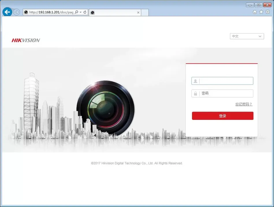
1. Log in to the camera address using IE browser, fill in the username and password.
2. Click on "Configuration"

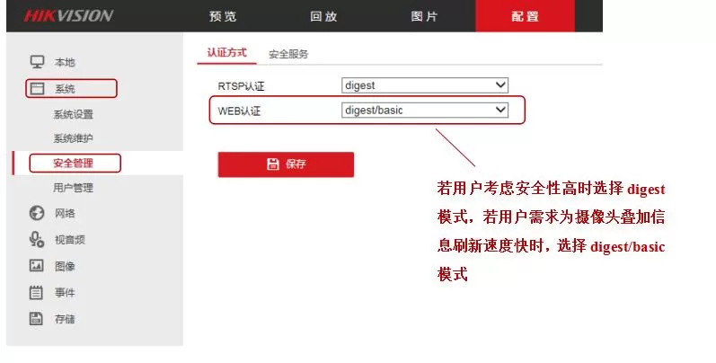
3. Click on "Configuration" to enter the camera configuration page. Click on Security Management in the system. Users choose the method of web authentication according to their needs. Suggest choosing the digest/basic mode.
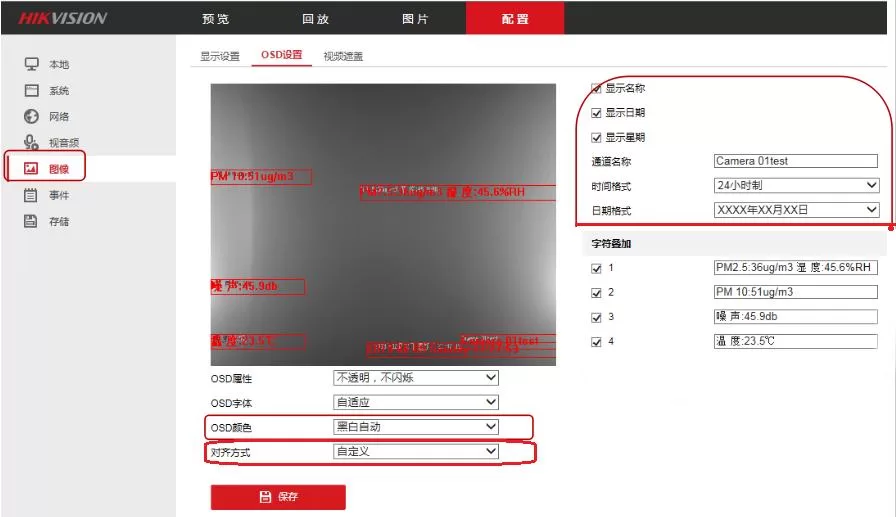
4. Click on the image → click on OSD settings. Users can check whether to display the name and date according to their needs, modify the OSD color to black and white automatically, and when the font matches the image color, it will automatically reverse for confirmation. The alignment method can be customized. After completing the changes, click 'Save'.
3.5.2 Huawei Camera Configuration
This explanation takes Huawei D3040-01-LI as an example.
1. Use IE browser or Google Chrome to log in to the camera address and fill in the username and password.
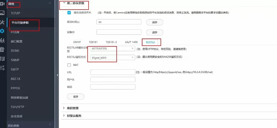
2. Log in to the camera web management interface, go to Advanced Configuration>Network>Platform Docking Parameters>Second Protocol Parameters>RESTful. The parameters are shown in the following figure and can be modified as follows: RESTful transmission protocol type: HTTP/HTTPS; RESTful authentication method: Digest_SD5
Camera version 10.0 and above interface is as follows:

3. Huawei camera northbound username and password default: ApiAdmin/HuaWei123. Fill in the camera username and password in the device configuration software according to this.

The northbound username for Huawei cameras is fixed as ApiAdmin, and the password can be changed as follows.
Camera version 900 camera northbound interface password is the password required for device configuration, which can be modified at the camera icon position:

4. Internal protocol
Communication basic parameters
| Encoding | 8-bit binary to hexadecimal conversion |
| Data bits | 8-bit |
| Parity bit | None |
| Stop bit | 1-bit |
| Error check | CRC (redundant cyclic code) |
| Baud rate | 2400~115200 can be set, factory default is 9600 bit/s |
5.Common problems and solutions
Camera does not display superimposed character information:
1. Check if the AB line of the 485 device is reversed
2. Check if the IP of the network video character adder, camera, and PC are in the same network segment
3. Check if the power supply of the video character adder is normal
4. Check if the power supply of the camera is normal
5. Check if the camera IP and target port settings in the configuration software are correct
6. Check if the baud rate setting in the configuration is correct
7. Check if the multi-channel camera is selected as a single channel camera
8. Check if the overlay number is enabled
9. Check if the 485 communication protocol is selected incorrectly
10. Corresponding slot number Is
not enabled? 11. Is the address and data type selected correctly?
12. Device damage
6.Precautions
1. Warning: Risk of personal injury. This equipment is strictly prohibited from being used as a safety device or emergency stop device, nor for any other purpose that may cause personal injury due to equipment failure. Usage restrictions: Only for authorized use as intended. Before installation, operation, or maintenance, it is necessary to consult the technical manual. Failure to follow the above guidelines may result in death or serious injury.
2. Containers containing liquids cannot be placed above the new network video character superimposer.
3. Please install the equipment in a well ventilated location.
4. The equipment should be installed within the allowable temperature and humidity range.
7.Warranty Statement
The warranty period is within 24 months from the date of purchase (subject to valid purchase certificate). During the warranty period, if the equipment itself has problems with its mechanical materials and processes, and malfunctions under normal use and maintenance, and it is verified to be true, our company will provide free repair and replacement of parts.
Beyond the warranty period, lifetime maintenance services will be provided. If one of the following conditions is met, it is not covered by the warranty:
If one of the following conditions is met, it is not covered by the warranty:
1. Equipment damage caused by incorrect installation, use, or operation of the product.
2. Any components inside the equipment have been disassembled, repaired, altered, modified, or replaced by non company technicians or by the user themselves.
3. Negligent use or damage caused by water or other substances entering the equipment.
4. Malfunctions or damages caused by natural disasters due to unexpected events.
5. Malfunctions or damages caused by exceeding the working parameter range listed in the product parameters


Leave a Reply