
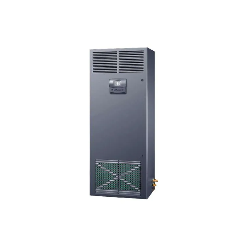
1. Overview
17.0~40.0℃
01H
This agreement applies to aircraft modelsMAV006S, MAV008S, MAV008, MAV008T, MAV013T, MAV018T.
2, Optional materials
| Specification and model | name | Brand |
| UT-204E | 485-232 converter | |
| Three core shielded wire | RS485 Connecting line | Customer provided |
3, Transmission mode
The air conditioning unitRS485The transmission mode is as follows::
| Baud rate | Data bits | Checksum | Stop position |
| 9600 | 8 | None | 2 |
4, Frame format
Air conditioning unit supportModbusThe agreementRTUFrame format. As follows::
| Address | Function codeFC | data Address | CRC |
| 1 byte | 1 byte | N bytes | 2 bytes |
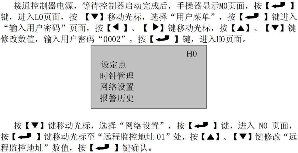
5, The communication address of the air conditioning unit (default remote monitoring address is
range from 1 to001)can be modified through manual operation255. remote monitoring address, function code.

6, supports the following function codesFC
function code:
| description | read coil status | read air conditioning operation status and alarm information and other discrete signals |
| 01 | each | represents, statusbit each byte represents1 status, 1=ON, 0=OFF, status8 less than 8 bits remaining additions, maximum number of reads at a time, connection0. continuation status200read class register. read input bit status0xxxx read air conditioning operation status and alarm information and other discrete signals. |
| 02 | each | represents, statusbit each byte represents1 status, 1=ON, 0=OFF, status8 less than 8 bits remaining additions, maximum number of reads at a time) The sentence is:, The remaining additions0. Can read at most once200Individual connection Continued state. Read1xxxx Class register. |
| 03 | Read and hold registers | Read the set values and operating parameters, Each data occupies 2 bytes, The first byte is the high byte, The second byte is the low byte, Read at most once 100A continuous register. Read4xxxx Register |
| 04 | Read input register | Read the set values and operating parameters, Each data occupies 2 bytes, The first byte is the high byte, The second byte is the low byte, Read at most once 100A continuous register. Read3xxxx Register |
| 05 | Write status | Write a status control bit, ON(0xFF00) , OFF(0x0000) . Write0xxxx Register |
| 06 | Write a single register | Write operational parameters, Each parameter occupies 2 bytes, The first byte is the high byte, The second byte is the low byte. Write4xxxx Register. |
7, data The length of the data domain varies depending on the command codes used in the request and response
Error verification.
8, Error verification is adopted
Modbus Bytes)16 bit(2 VerificationCRC (Cyclical Redundancy Check )Remote monitoring network connection.
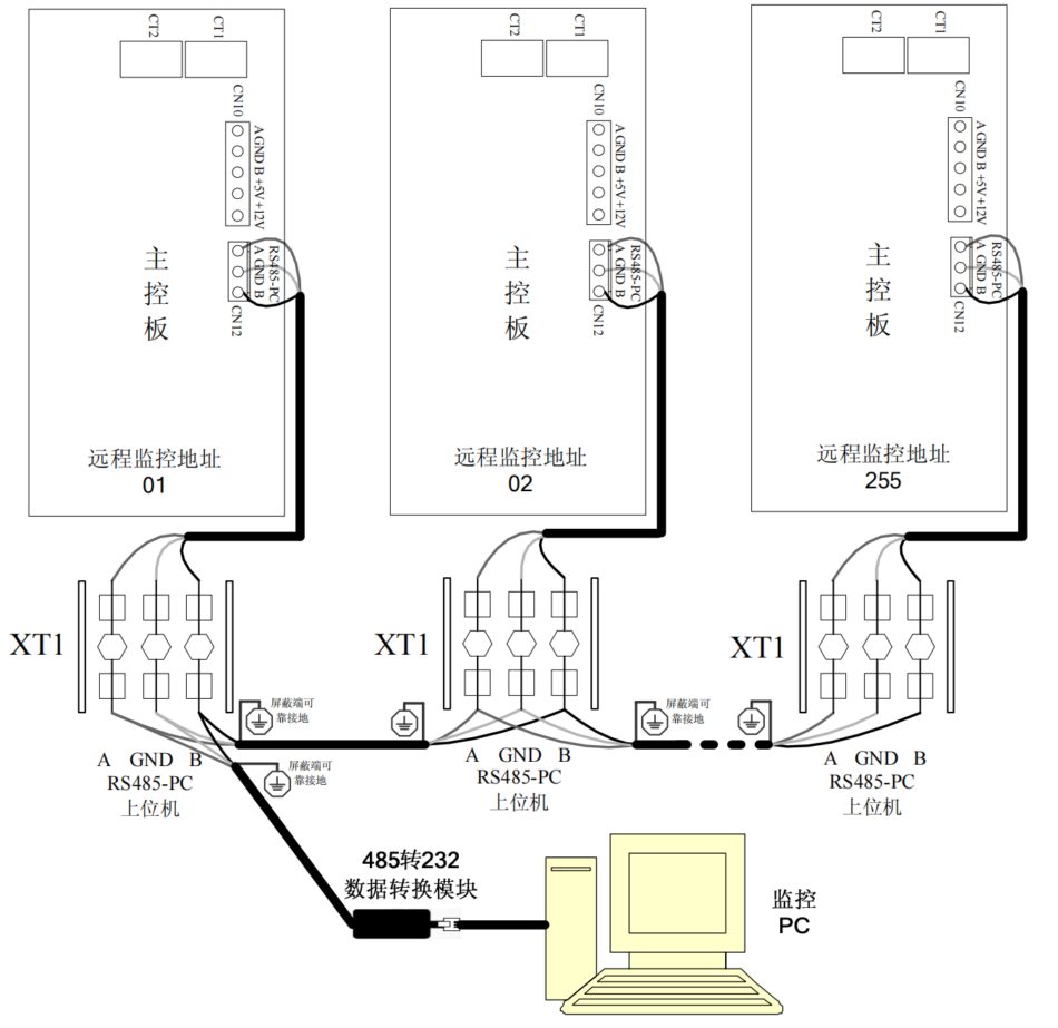
9, As shown in the following figure
The end has been connected to the three core shielded wireRS485-PCAt the terminal (please refer to the indoor unit wiring nameplate for detailsXT1press the button when using),wireA, GND, Bpolarity, correct connection is required (if the main control board cannot communicate normally during debugging, the wiring can be swapped and tried again, the total length of the wiring should not exceed meters note: to ensure the normal operation of the equipment, no data should be written to the reserved address, set parameters on the upper computerABif the cursor displayed on the manual operator is stuck in the page), RS485the manual operator page displays1200the information will not refresh.
when the cursor returns to the upper left corner of the page position):
1, To ensure the normal operation of the equipment, Cannot write any data to the reserved address.
2, Set parameters on the upper computer, If the cursor displayed on the handheld device stays on the page, The manual operator page displays
Information will not refresh, When the cursor returns to the top left corner of the page, The displayed information will only refresh.
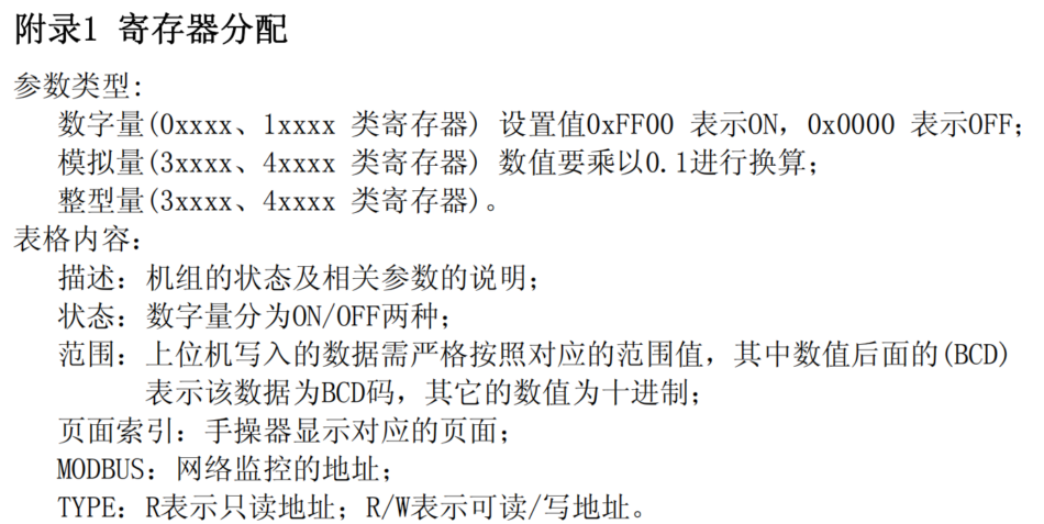
Table1 Numerical quantity
| Description | Status ON/OFF | Page index | MODBUS | TYPE |
| Remote power on/off function | Enable/disable | D8 | 1 | R/W |
| retain | - | - | 2- 16 | R |
| Allow host control function | Enable/disable | N5 | 17 | R/W |
| Setting time intervals for on/off | Enable/disable | Z1 | 18 | R/W |
| Set temperature time intervals | Enable/disable | Z1 | 19 | R/W |
| Setting points for humidity time periods | Enable/disable | Z1 | 20 | R/W |
| High temperature simultaneous opening function | Enable/disable | N7/U0 | 21 | R/W |
| Low temperature simultaneous opening function | Enable/disable | N8/U0 | 22 | R/W |
| Key on/off function | Enable/disable | D8 | 23 | R/W |
| retain | - | - | 24-36 | R |
| Forced cooling function | Enable/disable | D8 | 37 | R/W |
| Computer administrator reset alarm | Alarm/reset | - | 38 | R/W |
| Computer administrator power on/off group | Turn on/off | - | 39 | R/W |
| retain | - | - | 40 | R |
| Cooling mode | Enter/exit | M1 | 41 | R |
| Heating mode | Enter/exit | M1 | 42 | R |
| Humidification mode | Enter/exit | M1 | 43 | R |
| Dehumidification mode | Enter/exit | M1 | 44 | R |
| Air outlet restriction mode | Enter/exit | M2 | 45 | R |
| Dehumidification restriction mode | Enter/exit | M2 | 46 | R |
| Dehumidification temperature compensation mode | Enter/exit | M2 | 47 | R |
| Description | Status ON/OFF | Page index | MODBUS | TYPE |
| Internal fan | Turn on/off | S7 | 48 | R |
| compressor 1 | Turn on/off | S8 | 49 | R |
| compressor 2(reserve) | Turn on/off | S8 | 50 | R |
| Electric heating 1 | Turn on/off | S8 | 51 | R |
| Electric heating 2 | Turn on/off | S8 | 52 | R |
| Dehumidification | Turn on/off | S7 | 53 | R |
| Humidification | Turn on/off | S7 | 54 | R |
| Alarm output status | Turn on/off | S7 | 55 | R |
| Remote on/off (machine) | off/on | S4 | 56 | R |
| phase loss alarm | alarm/normal | - | 57 | R |
| low/high voltage alarm | alarm/normal | S6 | 58 | R |
| smoke alarm | alarm/normal | S5 | 59 | R |
| fire alarm | alarm/normal | S5 | 60 | R |
| water leakage alarm | normal/alarm | S5 | 61 | R |
| air flow alarm | alarm/normal | S3 | 62 | R |
| fan overload | alarm/normal | S3 | 63 | R |
| main controller EEPROM fault | alarm/normal | - | 64 | R |
| compressor 1 high pressure/overload | alarm/normal | S0 | 65 | R |
| compressor 1 high pressure/overload | alarm/normal | S1 | 66 | R |
| compressor 2 high pressure/overload (reserved) | alarm/normal | S0 | 67 | R |
| compressor 2 low pressure (reserved) | alarm/normal | S1 | 68 | R |
| heater 1 overload | alarm/normal | S3 | 69 | R |
| heater 2 overload | compressor | S3 | 70 | R |
| starting high pressure alarm 1 alarm/normal | alarm/normal | - | 71 | R |
| exhaust temperature protection 1 | alarm)/Normal | S1 | 72 | R |
| Exhaust temperature protection 2(Reserved) | Alarm/Normal | S1 | 73 | R |
| Humidifier alarm | Alarm/Normal | S4 | 74 | R |
| User defined alarm 1 | Alarm/Normal | S5 | 75 | R |
| External unit theft alarm | Alarm/Normal | S4 | 76 | R |
| Indoor high temperature alarm | Alarm/Normal | - | 77 | R |
| Indoor low temperature alarm | Alarm/Normal | - | 78 | R |
| High humidity alarm | Alarm/normal | - | 79 | R |
| Low humidity alarm | Alarm/normal | - | 80 | R |
| Air filter blockage alarm | Alarm/normal | S4 | 81 | R |
| The running time of the fan has exceeded the limit | Alarm/normal | - | 82 | R |
| retain | - | - | 83-84 | R |
| Humidifier running time timeout | Alarm/normal | - | 85 | R |
| Filter maintenance alarm | Alarm/normal | - | 86 | R |
| Indoor temperature probe malfunction | Alarm/normal | - | 87 | R |
| Indoor humidity probe malfunction | Alarm/normal | - | 88 | R |
| Malfunction of the outlet temperature probe | Alarm/normal | - | 89 | R |
| Description | Status ON/OFF | Page index | MODBUS | TYPE |
| Exhaust temperature probe 1 Fault | Alarm/normal | - | 90 | R |
| Exhaust temperature probe 2 Fault (reserved) | alarm/normal | - | 91 | R |
| evaporator tube temperature probe fault | alarm/normal | - | 92 | R |
| pressure probe 1 fault (reserved) | alarm/normal | - | 93 | R |
| pressure probe 2 fault (reserved) | alarm/normal | - | 94 | R |
| coil freezing alarm | alarm/normal | - | 95 | R |
| reserved | - | - | 96 | R |
| compressor 1 high current alarm | alarm/normal | - | 97 | R |
| reserved | - | - | 98 | R |
| exhaust pressure 1 high pressure alarm (reserved) | alarm/normal | - | 99 | R |
| reserved 2 exhaust pressure) | high pressure alarm (reserved | - | 100 | R |
| alarm/normal | - | - | 101- 105 | R |
| reserved 2 host/slave | communication fault | - | 106 | R |
| alarm/normal 3 host/slave | communication fault | - | 107 | R |
| alarm/normal 4 host/slave | communication fault | - | 108 | R |
| alarm/normal 5 Communication failure | Alarm/normal | - | 109 | R |
| Host/Slave 6 Communication failure | Alarm/normal | - | 110 | R |
| Host/Slave 7 Communication failure | Alarm/normal | - | 111 | R |
| Host/Slave 8 Communication failure | Alarm/normal | - | 112 | R |
| retain | - | - | 113 | |
| display EEPROM Fault | Alarm/normal | - | 114 | R |
Table2 Analog quantity
| Description | Range | Page index | MODBUS | TYPE |
| Temperature setting point | 17.0~40.0℃ | D1 | 1 | R/W |
| Time zone Actual temperature setting point | 17.0~40.0℃ | D0 | 2 | R |
| Humidity setting point | 30.0~70.0% | D1 | 3 | R/W |
| Time zone Actual humidity setting point | 30.0~70.0% | D0 | 4 | R |
| Temperature dead zone | 00.0~20.0℃ | D4 | 5 | R/W |
| Refrigeration deviation | 00.0~20.0℃ | D4 | 6 | R/W |
| Heating deviation | 00.0~20.0℃ | D4 | 7 | R/W |
| Humidification deviation | 00.0~90.0% | D5 | 8 | R/W |
| Dehumidification deviation | 00.0~90.0% | D5 | 9 | R/W |
| Minimum temperature setting point | 17.0~40.0℃ | D2 | 10 | R/W |
| Maximum temperature setting point | 17.0~40.0℃ | D2 | 11 | R/W |
| Minimum humidity setting point | 20.0~100.0% | D3 | 12 | R/W |
| Maximum humidity setting point | 20.0~100.0% | D3 | 13 | R/W |
| retain | -- | - | 14- 15 | R |
| High temperature same opening value | 00.0~40.0℃ | N7 | 16 | R/W |
| Low temperature same opening value | 00.0~40.0℃ | N8 | 17 | R/W |
| Indoor high temperature alarm value | 00.0~90.0℃ | D6 | 18 | R/W |
| Description | Range | Page index | MODBUS | TYPE |
| Indoor low temperature alarm value | 00.0~90.0℃ | D6 | 19 | R/W |
| High humidity alarm value | 00.0~100.0% | D7 | 20 | R/W |
| Low humidity alarm value | 00.0~100.0% | D7 | 21 | R/W |
| retain | -- | - | 22-24 | R |
| High temperature and switch back difference | 00.0~20.0℃ | N7 | 25 | R/W |
| Low temperature with same opening and closing difference | 00.0~20.0℃ | N8 | 26 | R/W |
| retain | -- | - | 27-33 | R |
| The 1 Time zone temperature setting point | 17.0~40.0℃ | Z5 | 34 | R/W |
| The 2 Time zone temperature setting point | 17.0~40.0℃ | Z5 | 35 | R/W |
| The 3 Time zone temperature setting point | 17.0~40.0℃ | Z6 | 36 | R/W |
| The 4 Time zone temperature setting point | 17.0~40.0℃ | Z6 | 37 | R/W |
| The 1 Time zone humidity setting point | 30.0~70.0% | Z7 | 38 | R/W |
| No. 2 Time zone humidity setting point | 30.0~70.0% | Z7 | 39 | R/W |
| The 3 Time zone humidity setting point | 30.0~70.0% | Z8 | 40 | R/W |
| The 4 Time zone humidity setting point | 30.0~70.0% | Z8 | 41 | R/W |
| retain | -- | - | 42-48 | R |
| Environmental temperature | C0/M0 | 49 | R | |
| ambient humidity | C0/M0 | 50 | R | |
| Air outlet temperature | C0 | 51 | R | |
| retain | -- | - | 52-54 | R |
| Humidifier control voltage value | 00.0~10.0V | Sa | 55 | R |
| retain | -- | - | 56 | R |
| Control voltage value of internal fan | 00.0~10.0V | Sa | 57 | R |
| External fan 1 Control voltage value (reserved) | 00.0~10.0V | Sb | 58 | R |
| condensing pressure 1 (reserved) | Sb | 59 | R | |
| external fan 2 control voltage value (reserved) | 00.0~10.0V | Sc | 60 | R |
| condensing pressure 2(reserved) | Sc | 61 | R | |
| reserved | -- | - | 62 | R |
table3 integer quantity
| description | range | page index | MODBUS | TYPE |
| fan running time | 0~65535hour | Y0 | 63 | R |
| compressor 1 running time | 0~65535hour | Y0 | 64 | R |
| compressor 2 running time) | 0~65535hour | Y0 | 65 | R |
| electric heating 1 running time | 0~65535hour | Y1 | 66 | R |
| electric heating 2 running time | 0~65535hour | Y1 | 67 | R |
| humidifier running time | 0~65535hour | Y1 | 68 | R |
| reserved | -- | - | 69-88 | R |
| rotation type(0 automatic/1 hour/2 time zone) | 00~02 | U0 | 89 | R |
| reserved | -- | - | 90-94 | R |
| equipment address (upper computer monitoring) | 001~255 | N0 | 95 | R/W |
| description | range | page index | MODBUS | TYPE |
| reserved | -- | - | 96-97 | R |
| time zone temperature setting hour 1 time zone temperature setting minute | 00~23 (BCD) | Z5 | 98 | R/W |
| time zone temperature setting hour 1 time zone temperature setting hour | 00~59 (BCD) | Z5 | 99 | R/W |
| time zone temperature setting minute 2 time zone temperature setting minute | 00~23 (BCD) | Z5 | 100 | R/W |
| time zone temperature setting hour 2 time zone temperature setting minute) | 00~59 (BCD) | Z5 | 101 | R/W |
| No. 3 Time Zone Temperature Setting Hours | 00~23 (BCD) | Z6 | 102 | R/W |
| No. 3 Time Zone Temperature Setting Minutes | 00~59 (BCD) | Z6 | 103 | R/W |
| The 4 Time zone temperature setting hours | 00~23 (BCD) | Z6 | 104 | R/W |
| The 4 Time zone temperature setting in minutes | 00~59 (BCD) | Z6 | 105 | R/W |
| The 1 Time zone humidity setting hours | 00~23 (BCD) | Z7 | 106 | R/W |
| The 1 Time zone humidity setting in minutes | 00~59 (BCD) | Z7 | 107 | R/W |
| The 2 Time zone humidity setting hours | 00~23 (BCD) | Z7 | 108 | R/W |
| The 2 Time zone humidity setting in minutes | 00~59 (BCD) | Z7 | 109 | R/W |
| The 3 Time zone humidity setting hours | 00~23 (BCD) | Z8 | 110 | R/W |
| The 3 Time zone humidity setting in minutes | 00~59 (BCD) | Z8 | 111 | R/W |
| The 4 Time zone humidity setting hours | 00~23 (BCD) | Z8 | 112 | R/W |
| The 4 Time zone humidity setting in minutes | 00~59 (BCD) | Z8 | 113 | R/W |
| Startup time zone F1- 1 Hour | 00~23 (BCD) | Z2 | 114 | R/W |
| Startup time zone F1- 1 minute | 00~59 (BCD) | Z2 | 115 | R/W |
| Shutdown time zone F1- 1 Hour | 00~23 (BCD) | Z2 | 116 | R/W |
| Shutdown time zone F1- 1 minute | 00~59 (BCD) | Z2 | 117 | R/W |
| Startup time zone F1-2 Hour | 00~23 (BCD) | Z2 | 118 | R/W |
| Startup time zone F1-2 minute | 00~59 (BCD) | Z2 | 119 | R/W |
| Shutdown time zone F1-2 Hour | 00~23 (BCD) | Z2 | 120 | R/W |
| Shutdown time zone F1-2 minute | 00~59 (BCD) | Z2 | 121 | R/W |
| Startup time zone F2 Hour | 00~23 (BCD) | Z2 | 122 | R/W |
| Startup time zone F2 minute | 00~59 (BCD) | Z2 | 123 | R/W |
| Shutdown time zone F2 Hour | 00~23 (BCD) | Z2 | 124 | R/W |
| Shutdown time zone F2 minute | 00~59 (BCD) | Z2 | 125 | R/W |
| On/off time zone Monday | 01~04 | Z4 | 126 | R/W |
| On/off time zone is Tuesday | 01~04 | Z4 | 127 | R/W |
| Power on/off time zone on Wednesday | 01~04 | Z4 | 128 | R/W |
| On/off time zone Thursday | 01~04 | Z4 | 129 | R/W |
| Power on/off time zone is Friday | 01~04 | Z4 | 130 | R/W |
| On/off time zone Saturday | 01~04 | Z4 | 131 | R/W |
| On/off time zone: Sunday | 01~04 | Z4 | 132 | R/W |
| retain | -- | - | 133- 168 | R |
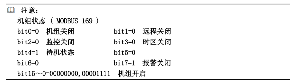
| Unit status | M0 | 169 | R/W | |
| retain | -- | - | 170 | R |
| minute | 00~59 (BCD) | M0/Z0 | 171 | R/W |
| Hour | 00~23 (BCD) | M0/Z0 | 172 | R/W |
| Description | Range | Page index | MODBUS | TYPE |
| Week | 01~07 (BCD) | Z0 | 173 | R |
| Day | 01~31 (BCD) | M0/Z0 | 174 | R/W |
| Month | 01~12 (BCD) | M0/Z0 | 175 | R/W |
| Year | 00~99 (BCD) | M0/Z0 | 176 | R/W |
Note Appendix:
Verification algorithm2 CRCAppendix
const unsigned8bit ModbusCRCHi[] =

{

0x00,0xc1,0x81,0x40,0x01,0xc0,0x80,0x41,0x01,0xc0,

0x80,0x41,0x00,0xc1,0x81,0x40,0x01,0xc0,0x80,0x41,

0x00,0xc1,0x81,0x40,0x00,0xc1,0x81,0x40,0x01,0xc0,

0x80,0x41,0x01,0xc0,0x80,0x41,0x00,0xc1,0x81,0x40,

0x00,0xc1,0x81,0x40,0x01,0xc0,0x80,0x41,0x00,0xc1,

0x81,0x40,0x01,0xc0,0x80,0x41,0x01,0xc0,0x80,0x41,

0x00,0xc1,0x81,0x40,0x01,0xc0,0x80,0x41,0x00,0xc1,

0x81,0x40,0x00,0xc1,0x81,0x40,0x01,0xc0,0x80,0x41,

0x00,0xc1,0x81,0x40,0x01,0xc0,0x80,0x41,0x01,0xc0,

0x80,0x41,0x00,0xc1,0x81,0x40,0x00,0xc1,0x81,0x40,

0x01,0xc0,0x80,0x41,0x01,0xc0,0x80,0x41,0x00,0xc1,

0x81,0x40,0x01,0xc0,0x80,0x41,0x00,0xc1,0x81,0x40,

0x00,0xc1,0x81,0x40,0x01,0xc0,0x80,0x41,0x01,0xc0,

0x80,0x41,0x00,0xc1,0x81,0x40,0x00,0xc1,0x81,0x40,

0x01,0xc0,0x80,0x41,0x00,0xc1,0x81,0x40,0x01,0xc0,

0x80,0x41,0x01,0xc0,0x80,0x41,0x00,0xc1,0x81,0x40,

0x00,0xc1,0x81,0x40,0x01,0xc0,0x80,0x41,0x01,0xc0,

0x80,0x41,0x00,0xc1,0x81,0x40,0x01,0xc0,0x80,0x41,

0x00,0xc1,0x81,0x40,0x00,0xc1,0x81,0x40,0x01,0xc0,

0x80,0x41,0x00,0xc1,0x81,0x40,0x01,0xc0,0x80,0x41,

0x01,0xc0,0x80,0x41,0x00,0xc1,0x81,0x40,0x01,0xc0,

0x80,0x41,0x00,0xc1,0x81,0x40,0x00,0xc1,0x81,0x40,

0x01,0xc0,0x80,0x41,0x01,0xc0,0x80,0x41,0x00,0xc1,

0x81,0x40,0x00,0xc1,0x81,0x40,0x01,0xc0,0x80,0x41,

0x00,0xc1,0x81,0x40,0x01,0xc0,0x80,0x41,0x01,0xc0,

0x80,0x41,0x00,0xc1,0x81,0x40

};

const unsigned8bit ModbusCRCLo[] =

{

0x00,0xc0,0xc1,0x01,0xc3,0x03,0x02,0xc2,0xc6,0x06,

0x07,0xc7,0x05,0xc5,0xc4,0x04,0xcc,0x0c,0x0d,0xcd,

0x0f,0xcf,0xce,0x0e,0x0a,0xca,0xcb,0x0b,0xc9,0x09,

0x08,0xc8,0xd8,0x18,0x19,0xd9,0x1b,0xdb,0xda,0x1a,

0x1e,0xde,0xdf,0x1f,0xdd,0x1d,0x1c,0xdc,0x14,0xd4,

0xd5,0x15,0xd7,0x17,0x16,0xd6,0xd2,0x12,0x13,0xd3,

0x11,0xd1,0xd0,0x10,0xf0,0x30,0x31,0xf1,0x33,0xf3,

0xf2,0x32,0x36,0xf6,0xf7,0x37,0xf5,0x35,0x34,0xf4,

0x3c,0xfc,0xfd,0x3d,0xff,0x3f,0x3e,0xfe,0xfa,0x3a,

0x3b,0xfb,0x39,0xf9,0xf8,0x38,0x28,0xe8,0xe9,0x29,

0xeb,0x2b,0x2a,0xea,0xee,0x2e,0x2f,0xef,0x2d,0xed,

0xec,0x2c,0xe4,0x24,0x25,0xe5,0x27,0xe7,0xe6,0x26,

0x22,0xe2,0xe3,0x23,0xe1,0x21,0x20,0xe0,0xa0,0x60,

0x61,0xa1,0x63,0xa3,0xa2,0x62,0x66,0xa6,0xa7,0x67,

0xa5,0x65,0x64,0xa4,0x6c,0xac,0xad,0x6d,0xaf,0x6f,

0x6e,0xae,0xaa,0x6a,0x6b,0xab,0x69,0xa9,0xa8,0x68,

0x78,0xb8,0xb9,0x79,0xbb,0x7b,0x7a,0xba,0xbe,0x7e,

0x7f,0xbf,0x7d,0xbd,0xbc,0x7c,0xb4,0x74,0x75,0xb5,

0x77,0xb7,0xb6,0x76,0x72,0xb2,0xb3,0x73,0xb1,0x71,

0x70,0xb0,0x50,0x90,0x91,0x51,0x93,0x53,0x52,0x92,

0x96,0x56,0x57,0x97,0x55,0x95,0x94,0x54,0x9c,0x5c,

0x5d,0x9d,0x5f,0x9f,0x9e,0x5e,0x5a,0x9a,0x9b,0x5b,

0x99,0x59,0x58,0x98,0x88,0x48,0x49,0x89,0x4b,0x8b,

0x8a,0x4a,0x4e,0x8e,0x8f,0x4f,0x8d,0x4d,0x4c,0x8c,

0x44,0x84,0x85,0x45,0x87,0x47,0x46,0x86,0x82,0x42,

0x43,0x83,0x41,0x81,0x80,0x40

};

unsigned16bit ModbusCRC16( unsigned8bit *puchMsg, unsigned16bit len) {

unsigned8bit hi = 0xff;

unsigned8bit lo = 0xff;

unsigned8bit i;

unsigned16bit crc;

while(len--)

{

i = hi ^ *puchMsg++;

hi = lo ^ ModbusCRCHi [ i ];

lo =ModbusCRCLo [ i ];

}

crc = hi;

crc <<= 8;

crc += lo;

return crc;

}
Frame examples3 MODBUS RTU Here are typical examples of air conditioning units
Frame interaction processQ/ROne communication is initiated by the main station, Main station sends, Send query request frame The air conditioning unit is based on the query frame from the main station, Send response frames with corresponding data, Function code. 1, Read the status of the coil01Request slave device
Read01Coil20-40Query request.
| 01Address of air conditioning unit | |
| Starting register high byte | 01H |
| FC | 01H |
| Starting register low byte | 00H |
| Read | 13H |
| High byte countbitRead | 00H |
| Low byte countbitHigh byte | 15H |
| CRCLow byte | 0CH |
| CRCRequest response | 00H |
| 01Address of air conditioning unit | |
| Response data byte count | 01H |
| FC | 01H |
| High byte | 03H |
| Byte 0 ( Coils 27-20 ) | FEH |
| Byte 1 ( Coils 35-28 ) | 4EH |
| Byte 2 ( Coils 43-36 ) | 0AH |
| CRCLow byte | E8H |
| CRCCoil | 19H |
The state of use 27-20 express FEH In the last data byte, The state of the coil is:, 40-36 Their states are: 0AH, Note Fill in all remaining positions OFF-ON-OFF-ON-OFF, Function code 3 Read input bit status 0.
2, Request to read the slave device02of The input bit status
Query request01Address of air conditioning unit117-138Starting register high byte.
| 02Starting register low byte | |
| Read | 01H |
| FC | 02H |
| High byte count | 00H |
| Read | 74H |
| Low byte countbitHigh byte | 00H |
| Low bytebitRequest response | 16H |
| CRCAddress of air conditioning unit | B9H |
| CRClow-order byte | DEH |
| 02Request response | |
| Address of air conditioning unit | 01H |
| FC | 02H |
| Response data byte count | 03H |
| Byte 0 ( Coils 124-117 ) | 20H |
| Byte 1 ( Coils 132-125 ) | 0BH |
| Byte 2 ( Coils 138-133 ) | 00H |
| CRCHigh byte | 7EH |
| CRCLow byte | B4H |
3, Function code03Read and hold registers
Request to read the slave device01of Register status10-11Query request.
| 03Address of air conditioning unit | |
| Starting register high byte | 01H |
| FC | 03H |
| Starting register low byte | 00H |
| Read register with high byte count | 09H |
| Read low byte register quantity | 00H |
| High byte | 02H |
| CRCLow byte | 14H |
| CRCRequest response | 09H |
| 03Address of air conditioning unit | |
| Response data byte count | 01H |
| FC | 03H |
| data High byte | 04H |
| data Low byte 0 data High byte( 108 ) | 00H |
| data High byte 0 High byte( 108 ) | ACH |
| Low byte 1 Function code( 109 ) | 01H |
| Read input register 1 Request to read the slave device( 109 ) | 90H |
| CRCIn the middle | 3BH |
| CRCRegister | EEH |
4, Query request04Address of air conditioning unit
Starting register high byte01Starting register low byte009Read register with high byte count.
| 04Read low byte register quantity | |
| High byte | 01H |
| FC | 04H |
| Low byte | 00H |
| Request response | 08H |
| Address of air conditioning unit | 00H |
| Response data byte count | 01H |
| CRCdata High byte | B0H |
| CRCdata Low byte | 08H |
| 04High byte | |
| Low byte | 01H |
| FC | 04H |
| Function code | 02H |
| Write status 0 Mandatory slave devices( 009 ) | 00H |
| In the middle 0 The position is( 009 ) | 33H |
| CRCStatus | F9H |
| CRCTable 1 Digital quantity address | 25H |
5, For05Computer Administrator Power On/Off Group
Mandatory slave device01in39Position isONStatus (Table 1 Digital quantity address39for“Computer Administrator Power On/Off Group”, This address operation can achieve remote monitoring of power on/off groups).
| 05Set request | |
| Address of air conditioning unit | 01H |
| FC | 05H |
| Register high byte | 00H |
| Register low byte | 26H |
| Set high byte value | FFH |
| Set low byte value | 00H |
| CRCHigh byte | 6DH |
| CRCLow byte | F1H |
| 05Request response | |
| Address of air conditioning unit | 01H |
| FC | 05H |
| Register high byte | 00H |
| Register low byte | 26H |
| Set high byte value | FFH |
| Set low byte value | 00H |
| CRCHigh byte | 6DH |
| CRCLow byte | F1H |
6, Function code06Write a single register
Request to transfer the slave device01In the middle001Register preset as00F2HValue (Table 2 Analog quantity address001Yes“Temperature Set point”, Operating on this address can change the temperature setting value).
| 06Set request | |
| Air conditioning unit address | 01H |
| FC | 06H |
| Register high byte | 00H |
| Register low byte | 00H |
| Set value high byte | 00H |
| Set value low byte | F2H |
| CRCHigh byte | 08H |
| CRCLow byte | 4FH |
| 06Request response | |
| Air conditioning unit address | 01H |
| FC | 06H |
| Register high byte | 00H |
| Register low byte | 00H |
| Set value high byte | 00H |
| Set value low byte | F2H |
| CRCHigh byte | 08H |
| CRCLow byte) | 4FH |


Leave a Reply