
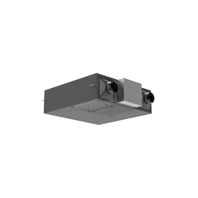
1. Applicable models of total heat exchangers
Household thin total heat exchanger
FY- 15ZDP1C, FY-25ZDP1C, FY-35ZDP1C, FY-50ZDP1C
FY- 15GZD1, FY-25GZD1, FY-35GZD1, FY-50GZD1
FY-RZ18DP1, FY-RZ28DP1 , FY-RZ38DP1
Commercial total heat exchanger
FY- 15ZY1C, FY-25ZY1C, FY-35ZY1C
FY-50ZY1C, FY-65ZY1C, FY-80ZY1C
FY- 1KZY1C , FY- 1HZY1C, FY-2KZY1C
Household thin total heat exchanger (suitable for cold regions)
FY- 15ZDP1CX, FY-25ZDP1CX, FY-35ZDP1CX
total heat exchanger (cabinet type fresh air fan)
FY-50ZR1C , FY-70ZR1C
| power supply | DC 5V |
| rated power | 0 .25W |
| weight | 0 .06kg |
| operating environment | temperature: - 10℃~40℃/relative humidity: 85%RHbelow |
| information transmission mode | start stop synchronization mode start bit:1bit, data bit:8bit, stop bit:1bit, parity check bit: none |
| check field | adoptedMODBUS-RTUmode16bitCRC(circuit lengthy check). |
| protocol basic form | Modbusframework structure |
| address bar | effective range of address1~63 |
| data area | Modbusbyte order used in data area, Big-Endian. (high-order byte→low order byte) |
| data transmission speed | 9600bps |
communication protocol usageModbus Protocol, use during serial transmissionRTUmode.
developed according to the following standards.
GB/T 19582 . 1-2008 industrial automation network specification based on protocol Part 1Modbusindustrial automation network specification based on protocol Part 2) Partial
GB/T 19582 .2-2008 Communication framework structure as followsModbusName
Initial end:
| ① | ② | ③ | ④ | ⑤ | ⑥ | |
| Machine address | Function code | Data | Verification code | Terminal | Byte count | Default interval |
| Default interval | Starting point | 1 | 1 | n | 2 | set up |
①The default range above (no communication time: machine address3 .65msspecified connection) .
②machine address of the module: setting method refers to the items set in the following address settingsRS485function code. (available function codes are as follows)
③function code: (content)
| Function code | Content | Function description |
| 0x03 | Read registers | Read the value of the register |
| 0x06 | Write to register | Write (single) set value |
| 0x10 | Write into complex registers | Write (complex) set values |
④data The composition of the data department may vary depending on the function code and register address: Refer to the communication framework setting case in the attachment. (Verification code)
⑤use: The patternModbus-RTUPosition16The calculated value of the lengthy inspection tourCRCRegarding.
Please refer to the standard for the calculation methodCRCTerminalGB/T 19582 .2-2008
⑥set up: The default range on the device (no communication time3 .65msmachine address setting).
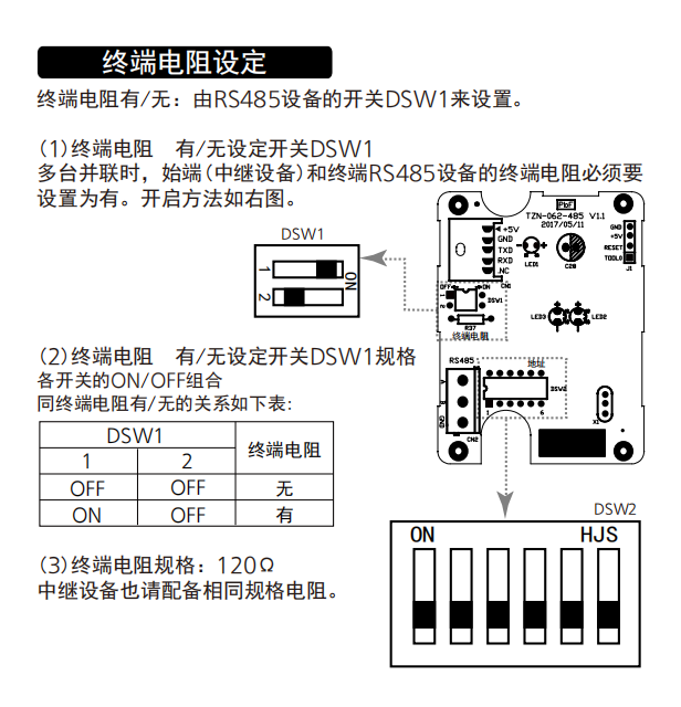
machine address setting based on
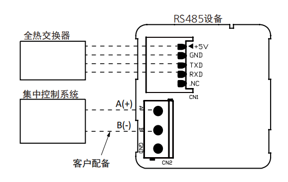
device'sRS485to setDSW2address setting switch.
(2)each switch'sDSW2
combination and machine address relationship are shown in the table belowON/OFFregister address list:

the register addresses used for module communication are shown in the table below (the range of continuously accessible complex register addresses is as followsRS485read)
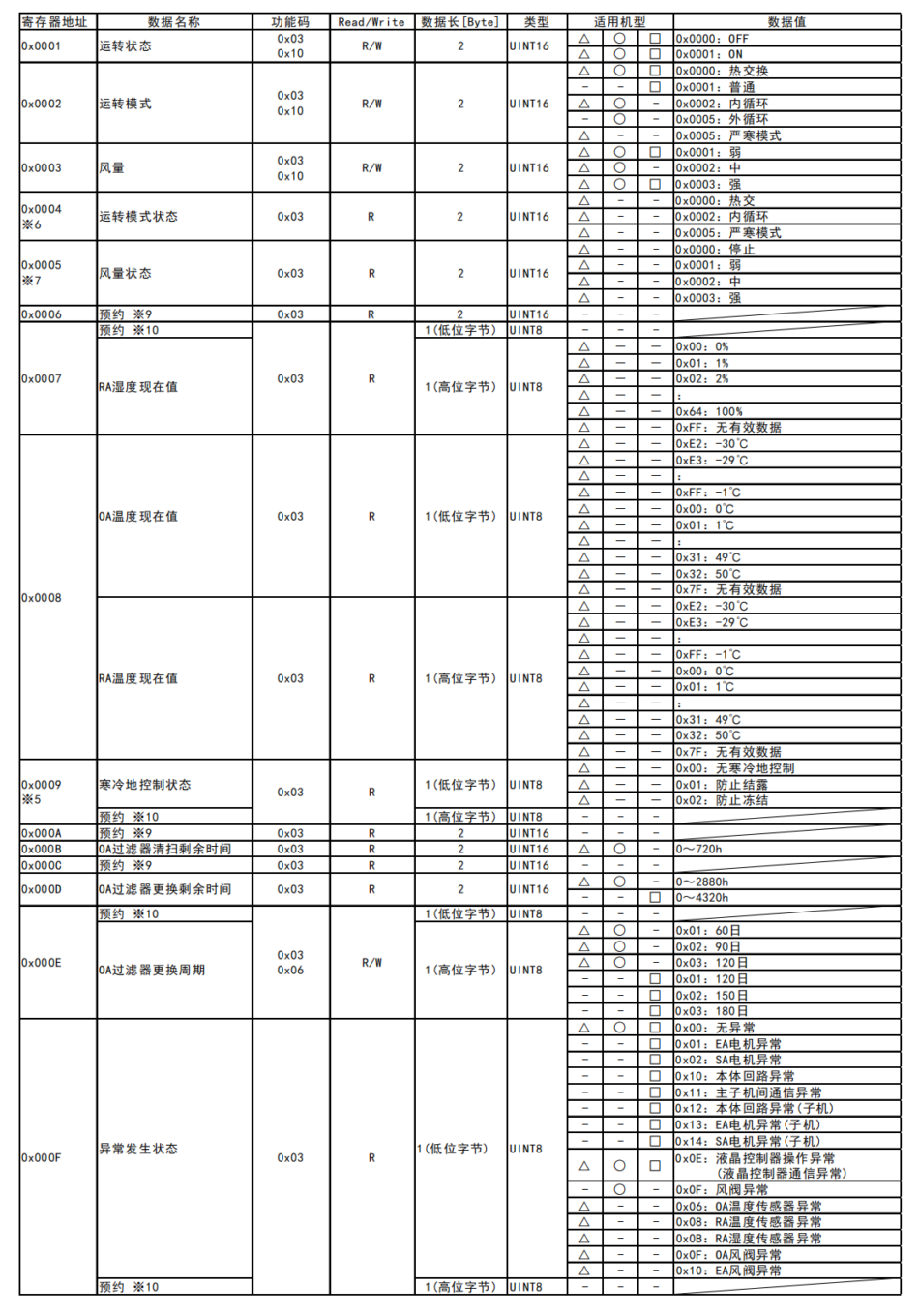
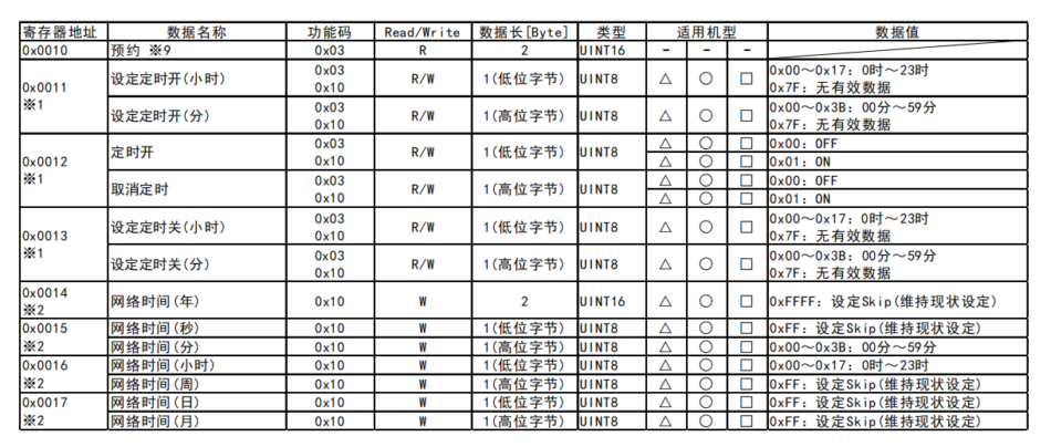
function code:
・write (when reading: 0x03) : 0x0001~0x0013
・please use function code (read together: 0x10) : 0x0001~0x0003, 0x0011~0x0013, 0x0014~0x0017
※1 write together, please use function code0x03write together complex register address (0x0011~0x0013) for example, "set timing on;
hour, minute0x10" set timing off (0x0011~0x0013) hour;
(minute) "when this is set, the machine address is 2when writing, please use function code50CodeON, write the address of the complex register together19Example:" Network time43hourONminute (The machine address is0x01) .
01 10 00 11 00 03 06 32 02 01 01 2B 13 C4 03
※2 When writing, Please use the function code0x10Address the complex register (0x0014~0x0017) Write it all together;
(Example) Network Time(17time40minute00When set in seconds (The machine address is0x01) .
01 10 00 14 00 04 08 FF FF 28 FF FF 11 FF FF B5 DC
※3 ModbusMaster node (Centralized control device) 150When there are no read or write requests within seconds, Detecting network anomalies.
※4 ○Suitable for household thin total heat exchangers; □Suitable for commercial total heat exchangers; △Suitable for household thin total heat exchangers (Cold ground models) .
※5 Whether the anti condensation protection or anti freezing protection for cold ground control has been activated.
※6 The operating mode of the anti condensation protection or anti freezing protection action controlled in cold regions.
(When the cold controlled protection does not operate, Operating mode0x0002The values are the same)
※7 The air volume during the cold control to prevent condensation protection or freezing protection action.
(When the cold controlled protection does not operate, Regarding air volume0x0003The values are the same)
※8 Please do not access undefined register addresses.
※9 It is the address of the 'reservation' register. Invalid read value.
※10 It is the field of "appointment" data. Read values, Invalid write value


Leave a Reply