
1. Product Introduction
1.1 Product Overview
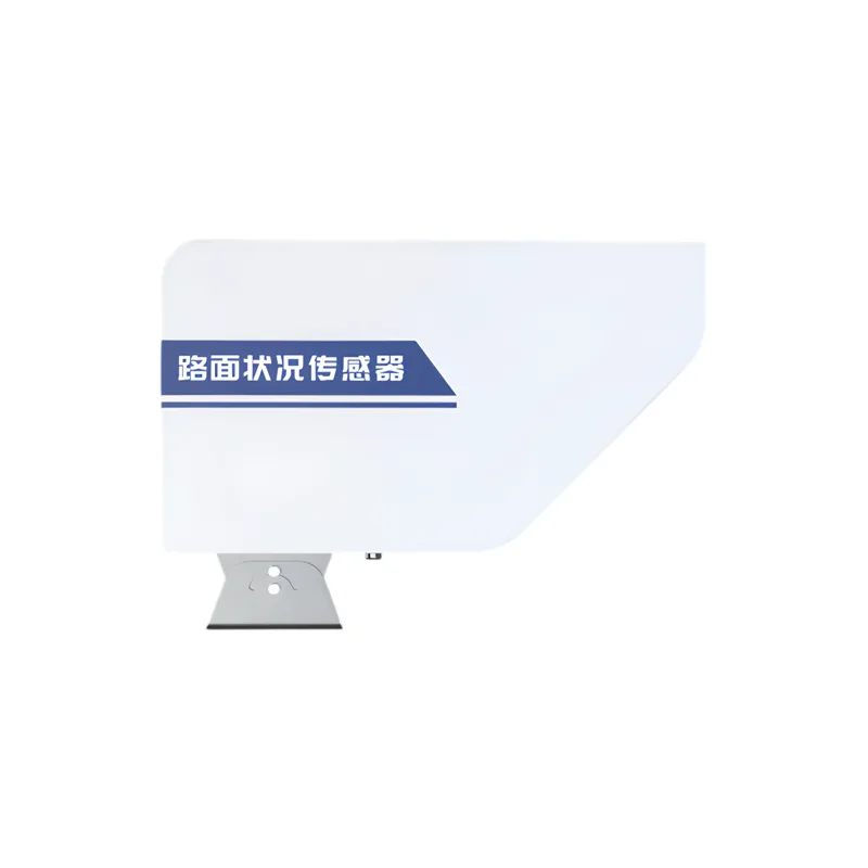
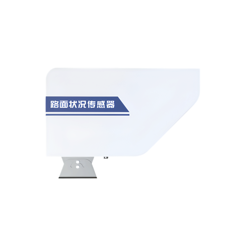
Road condition sensor, also known as road condition detector or remote sensing road sensor, is a key device that uses advanced remote sensing technology to monitor road conditions in real time. It adopts a non-contact detection mode, which emits light and receives spectral information reflected back from the road surface, achieving accurate measurement of road conditions such as ice, snow, water accumulation and their thickness.
The working principle of road condition sensors is mainly based on spectral analysis technology. The sensor has a built-in light source that emits monochromatic light of a single wavelength, which is focused by a lens and directed onto the road surface. Due to differences in road surface materials and conditions, the intensity and spectral characteristics of reflected light may also vary. The spectral receiving device inside the sensor can accurately measure the intensity and wavelength of reflected light, and analyze and interpret the spectral data through an internal processing unit, ultimately outputting the analysis results of road conditions such as dry, wet, icy, etc.
is widely used in various transportation scenarios, including highways, urban roads, airport runways, bridges and tunnels, etc.
Purchase Product:https://www.modbus.cn/product/31017.html
1.2 Functional Features
- Multi parameter Measurement: Sensors can measure various road parameters, including road temperature, status (dry, wet, wet, accumulated water, etc.), water film height, ice layer thickness, snow thickness, etc.
- Simple structure, good stability, high reliability, low energy consumption, easy use and maintenance.
- Laser light source, Add laser design and anti light source interference.
- Equipment surface undergoes anti-corrosion treatmentto resist rainwater corrosion. Real time monitoring of road conditions, providing timely feedback to take appropriate measures.
- Real time monitoring of road conditionsTimely feedback information to take corresponding measures.
- Non contact detection principleBy using remote sensing technology to obtain road information from a distance, there is no need to directly contact the road surface, thus avoiding damage to the road.
- DC power supply circuitIt has a dual design of anti reverse connection and self recovery insurance.
- The device comes with built-in lens heatingIt can effectively prevent frost formation on winter lenses.
1.3 Main technical indicators
| power supply | 11~28V DC |
| Measuring distance and measuring diameter | 2-10m, 25cm |
| Range of angle between sensor and vertical column | 0~60° |
| Road condition | Dry, damp, wet, waterlogged, frozen, snow (optional) |
| Thickness of accumulated water | 0.00~2.00mm |
| Ice thickness | 0.00~2.00mm (customizable) |
| Snow thickness (optional) | 50mm~2500mm |
| Road surface temperature | -30℃~60℃ |
| Wet and slippery degree ¹ | 0.00~1.00 (dangerous~dry) |
| update interval | 20s |
| Temperature resistance of transmitter components | -40~80℃ |
| Relative humidity at work | Not exceeding 95% (30 ℃) |
| power consumption | 1.5W (heating power 13W) |
| output method | 4G / RS485 |
¹ For reference only, the numerical values represent the friction capacity of the road surface and tires.
The performance data stated above was obtained under testing conditions using our company's testing system and software. In order to continuously improve our products, our company reserves the right to change design features and specifications without prior notice.
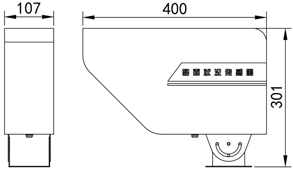
1.4 Equipment dimensions
Unit: mm
2. Product selection
Note: Please purchase the matching tray separately.
| RS - | Road condition sensor | ||
| LMK - | 4G Upload/RS485 | ||
| N01 | Type 1 |
3. Equipment Installation Instructions
3.1 Pre installation Inspection
■ One Road Condition Sensor
■ One Cross Arm
■ One Clamp
■ Installation Screws (M5 *55 Hexagonal Screws* 3, M5 Nut)*3, M8* 70 hex screws *3, M8 nuts* 3)
3.2 Installation instructions and precautions
(1) Remove the instrument from the packaging box, carefully count and check whether the equipment accessories are complete according to the packing list in the instruction manual.
(2) Carefully read the product manual and product certificate.
(3) Choose a suitable location to install the equipment. The equipment provides a crossbeam and installation clamps. First, install the equipment onto the crossbeam.
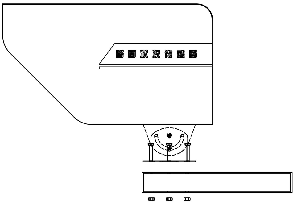
Then install the equipment onto a 75mm pole using clamps on the crossbeam.
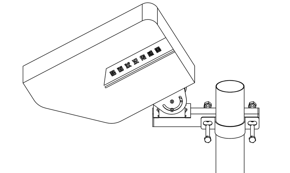
The measurement distance of each installation location is different, and the road condition sensor needs to be used accordingly. By adjusting the installation height or the angle between the device and the installation bracket, the measurement position can be adjusted. When adjusting the angle, the device's installation angle value can be viewed in the real-time data of the mobile configuration app, with a recommended range of 10-40 °.
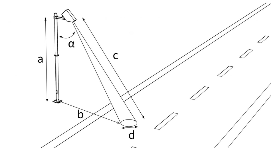
Note:: Based on the installation angle and height, calculate the measurement distance c and the approximate range d of the measurement position. Measure
and measure the distance b=installation height a * tan installation angle α. If the position is not ideal, adjust the sensor installation angle and height.
3.3 Equipment Wiring
Wide voltage power supply can input 10-30V.
| line color | Explanation |
|---|---|
| brown | Positive power supply |
| black | Negative power supply |
| yellow | 485-A |
| blue | 485-B |
4. Device Configuration Instructions
4.1 Device Configuration
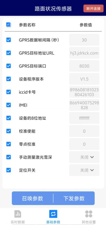
1) The device supports Bluetooth configuration and requires downloading the configuration software "Multi functional Parameter Configuration App" on the mobile phone, which can be downloaded by scanning the QR code. After the download is complete, turn on Bluetooth and open the APP software interface as shown below. Click on the device name LMK and the device address. For example, if the device address is 12345678, select LMZK12345678 (default password 12345678).

2) After the download is complete, turn on Bluetooth and open the APP software interface. Click on the device name LMK and the device address. For example, if the device address is 12345678, select LMZK12345678 (default password 12345678).
3) Users can view terminal addresses, target address port settings, target address settings, and other operations within the APP.
4.2 Equipment Calibration Instructions
4.2.1 Road Condition Calibration
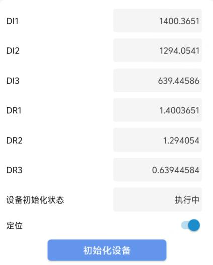
When the equipment is first installed or the installation position is changed, it needs to be recalibrated. During equipment calibration, the road surface should be kept dry and unobstructed. In the "Device Debugging" interface, click "Initialize Device", and the device will start automatic calibration. The device initialization status will display "Running", and a red dot will appear on the road surface facing the device lens. The diameter of the red dot within 25cm is the calibration area. The device calibration will last for about 5 minutes. When the red dot on the ground disappears, the device calibration is complete.
4.2.2 Snow Depth Calibration
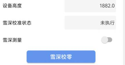
If snow depth elements are selected, snow depth calibration should be performed after the road surface calibration is completed. During equipment calibration, the road surface should be kept dry and unobstructed. In the "Device Debugging" interface, click "Snow Depth Zero Calibration", and the device will start automatic calibration. When calibrating, a red dot will appear on the road surface facing the device lens, which is the calibration point. The device calibration will last for about 10 seconds. When the red dot on the ground disappears, the device calibration is complete.
4.3 Device Dictionary and Real time Data Options Description
4.3.1 Device Dictionary
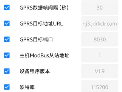
- GPRS data frame interval (seconds): The interval time during which the device actively uploads data, which is the update time of the data collector. If users have high requirements for data update time, this time can be set shorter; If users want to reduce network load, they can set this time to be long, ranging from 1 to 60000 seconds. Generally, users can set it to 30 seconds, meaning that the device sends data every 30 seconds. (Default: 30s)
- GPRS Target Address URL: Fill in the public IP address of the server where the temperature and humidity monitoring platform is located. If the platform has enabled domain name resolution services, you can fill in the corresponding server domain name.
- GPRS Target Port: The network listening port of the monitoring platform must be consistent with the platform port. (Default: 8030)
- Host ModBus Slave Address: 4G Select Equipment Please ignore this option, only 485 Select Equipment takes effect.
- Baud rate: Please ignore this option for 4G selection devices, only 485 selection devices will take effect.
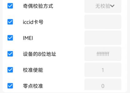
- Parity Check Method: Please ignore this option for 4G selection devices, only 485 selection devices will take effect.
- ICCID Number: The ICCID number of the SIM card inside the device.
- 8-bit address of the device: It is the unique address of the device, and the software monitoring platform distinguishes different devices based on this address. (Non modifiable)
- Calibration Enable: After installation is complete, write 1 in this field and the device will automatically start calibration (if the road surface is dry and unobstructed). After calibration, it takes about 5 minutes to change from 1 to 0.
- Zero point calibration: After installation, write 1 in this field, and the device will automatically calibrate the snow depth zero point (with dry and unobstructed road surface). After calibration is completed, it takes about 10 seconds to change from 1 to 0.
Note:: Some menus that are not specified have been set up at the factory, please do not modify them!
4.3.2 Real time data
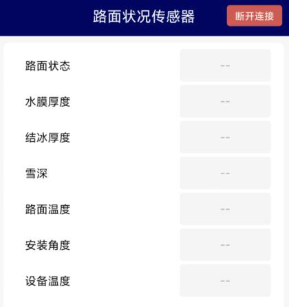
● Node 0-5:Node corresponding data is shown in the following table
| Node | Description | Data Type |
|---|---|---|
| 0 | Road Surface Status | 32-bit unsigned shaping 0: Error 1: Dry 2: Tide 3: Wet 4: Accumulated Water 7: Frozen |
| 1 | Accumulated Water Depth | Floating Point |
| 2 | Ice Thickness | Floating Point |
| 3 | Snow Depth (optional) | Floating Point |
| 4 | Road Temperature | Floating Point |
| 5 | Installation Angle | Floating Point |
5. PC Configuration Software Installation and Use
5.1 Software Selection
If you need to modify the device's address and baud rate, you need to use this configuration software for settings. Open the package, select "Debugging Software" ->"485 Parameter Configuration Software", find and open it.

Attention: When using this configuration software, a single device must be connected! Equipment wiring
5.2 Parameter settings
- Select the correct COM port (view COM port in "My Computer - Properties - Device Manager - Ports"), and the following figure lists several different 485 converter driver names.
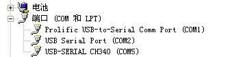
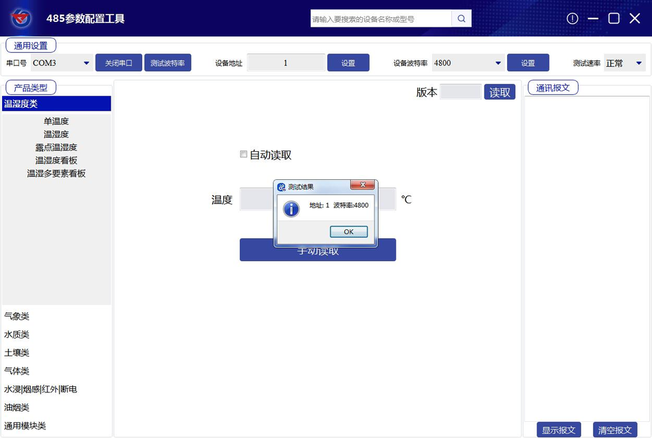
- Connect only one device and power it on. Click on the software's test baud rate, and the software will test the current device's baud rate and address. The default baud rate is 4800bit/s and the default address is 0x01.
- Modify the address and baud rate according to usage needs, and also query the current functional status of the device. If the test is unsuccessful, please recheck the equipment wiring and 485 driver installation.
- If the test is unsuccessful, please recheck the device wiring and 485 driver installation.
5.3 Equipment Calibration Instructions
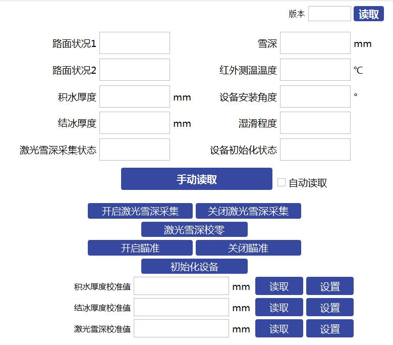
By selecting road condition equipment in meteorological classification, real-time data of the equipment can be viewed. At the same time, when the equipment is first installed or the installation position is changed, the transaction will recalibrate the equipment. During equipment calibration, the road surface must be kept dry and unobstructed. In the "Device Debugging" interface, click "Initialize Device", and the device will start automatic calibration. The device initialization status will be displayed as "In Progress", and a red dot will appear on the road surface facing the device lens. The diameter of the red dot within 25cm is the calibration area. The device calibration will last for about 5 minutes. When the red dot on the ground disappears, the device calibration is completed. If the snow depth element is selected, the snow depth calibration should be carried out after the road condition calibration is completed. During equipment calibration, the road surface should be kept dry and unobstructed. In the "Device Debugging" interface, click on "Snow Depth Zero Calibration", and the device will start automatic calibration. During calibration, a red dot will appear on the road surface facing the device lens, which is the calibration point. The device calibration will last for about 10 seconds. When the red dot on the ground disappears, the device calibration is complete.
If the snow depth element is selected, the snow depth calibration should be carried out after the road condition calibration is completed. During equipment calibration, the road surface should be kept dry and unobstructed. In the "Device Debugging" interface, click on "Snow Depth Zero Calibration", and the device will start automatic calibration. During calibration, a red dot will appear on the road surface facing the device lens, which is the calibration point. The device calibration will last for about 10 seconds. When the red dot on the ground disappears, the device calibration is complete.
6. Communication Protocol
6.1 Basic Communication Parameters
| Project | Parameters |
|---|---|
| Encoding | 8-bit binary |
| Data bits | 8-bit |
| Parity check bits | None |
| Stop bits | 1-bit |
| Error check | CRC (redundant cyclic code) |
| Baud rate | 1200bit/s, 2400bit/s, 4800bit/s, 9600bit/s, 19200bit/s, 38400bit/s, 57600bit/s, 115200bit/s can be set, factory default is 4800bit/s |
6.2 Data Frame Format Definition
Adopting ModBus RTU communication protocol, the format is as follows:
- Initial structure ≥ 4 bytes time
- Address code=1 byte
- Function code=1 byte
- Data area=N bytes
- Error check=16 bit CRC code
- End structure ≥ 4 bytes time
Address code: The address of the transmitter is unique in the communication network (default 0x01 at the factory).
Function Code: The instructions issued by the host indicate the function. This transmitter uses function codes 0x03 (read register data), 0x06 (write to a single register), and 0x10 (write to multiple registers).
Data Area: The data area contains specific communication data, please note that the high byte of the 16 bit data comes first!
CRC code: A two byte checksum.
Host query frame structure:
| Address code | Function code | Register start address | Register length | Check code low | Check code high |
|---|---|---|---|---|---|
| 1 byte | 1 byte | 2 bytes | 2 bytes | 1 byte | 1 byte |
Slave response frame structure:
| Address code | Function code | Return valid byte count | Data area 1 | Second data area | Nth data area | Check code |
|---|---|---|---|---|---|---|
| 1 byte | 1 byte | 1 byte | 2-byte | 2-byte | 2-byte | 2-byte |
6.3 Register Address
| Register Address (hexadecimal) | PLC or Configuration Address (decimal) | Content | Operation |
|---|---|---|---|
| 0000 H | 40001 | Road Status 0: Error 1: Dry 2: Tide 3: Wet 4: Accumulated water 7: Ice formation | 03 |
| 0001 H | 40001 | Road condition 0: Error 1: Dry 2: Tide 3: Wet 4: Accumulated water 7: Ice formation | 03 |
| 0002 H | 40003 | Thickness of accumulated water, floating point type, high position | 03 |
| 0003 H | 40003 | Thickness of accumulated water, floating point type, low position | 03 |
| 0004 H | 40005 | Ice thickness floating point high position | 03 |
| 0005 H | 40006 | Ice thickness floating point type low position | 03 |
| 0006 H | 40007 | Snow depth floating point high position | 03 |
| 0007 H | 40008 | Floating point low-level snow depth | 03 |
| 0008 H | 40009 | Floating point high position for road surface temperature | 03 |
| 0009 H | 40010 | Road surface temperature floating point low position | 03 |
| 000A H | 40011 | Equipment installation angle floating point high bit | 03 |
| 000B H | 40012 | Equipment installation angle floating point type low bit | 03 |
| 000C H | 40013 | Wet and slippery degree floating point high position | 03 |
| 000D H | 40014 | Wet and slippery degree, floating point type, low bit | 03 |
| 0013 H | 40020 | Positioning enablement 0: Turn off the laser beam 1: Turn on the laser beam | 03/06/10 |
| 0015 H | 40022 | Road calibration enable Write 1 for automatic calibration | 03/06/10 |
| 0056 H | 40087 | Calibration value of accumulated water thickness 16 bit unsigned, enlarged by 100 times | 03/06/10 |
| 0057 H | 40088 | Ice thickness calibration value 16 bit unsigned, enlarged by 100 times | 03/06/10 |
| 0058 H | 40089 | Ice thickness calibration value 16 bit unsigned, enlarged by 100 times | 03/06/10 |
| 0061 H | 40098 | Laser snow depth calibration Write 1 Automatic Zero Calibration | 03/06/10 |
| 07D0 H | 42001 | Device Address 1~254 | 03/06/10 |
| 07D1 H | 42002 | Baud Rate 0 represents 2400 1 represents 4800 2 represents 9600 3 represents 19200 4 represents 38400 5 represents 57600 6 represents 115200 7 represents 1200 | 03/06/10 |
6.4 Communication Protocol Examples and Explanations
Read the road status of device address 0x01
- Inquiry frame (hexadecimal):
- Address code, function code, starting address, data length, check code, low bit, check code, high bit
- 0x01 0x03 0x00 0x00 0x00 0x01 0x84 0x0A
- Response frame (hexadecimal): (e.g. reading road surface status as dry)
- Address code function code returns the number of valid bytes, road status verification code, low bit verification code, high bit verification code
- 0x01 0x03 0x02 0x01 0x79 0x84
Visibility calculation: 0001 H (hexadecimal)=1=>Road condition=Dry
Read device address 0x01's accumulated water thickness
- Inquiry frame (hexadecimal):
- Address code Function code Starting address Data length Verification code Low bit Check code High bit
- 0x01 0x03 0x01 0x02 0x95 0xCB
- Response frame (hexadecimal): (e.g. read accumulated water thickness of 0.5mm)
- Address code Function code Return valid byte count High bit accumulated water thickness Low bit Check code Low bit Check code High bit Check code
- 0x01 0x03 0x04 0x3F 0x00 0x00 0x00 0xF6 0x27
Calculation of accumulated water thickness: 3F00 0000 H (hexadecimal)=0.5=>Accumulated water thickness=0.5mm
Modify the current address
- Inquiry frame: (If the current address is 01, the address needs to be changed to 02)
- Address code, function code, starting address, modifying numerical value, verification code, low bit, verification code, high bit
- 0x01 0x06 0x07 0xD0 0x00 0x02 0x08 0x86
- Response frame:
- Address code, function code, starting address, modifying numerical value, verification code, low bit, verification code, high bit
- 0x01 0x06 0x07 0xD0 0x00 0x02 0x08 0x86
Modify the current baud rate
- Inquiry frame: (If the current baud rate is 4800, change it to 9600)
- Address code, function code, starting address, modifying numerical value, verification code, low bit, verification code, high bit
- 0x01 0x06 0x07 0xD1 0x00 0x02 0x59 0x46
- Response frame:
- Address code Function code Start address Modify numerical value Check code Low bit Check code High bit
- 0x01 0x06 0x07 0xD1 0x02 0x59 0x46
Query address
- Inquiry frame:
- Address code, function code, starting address, data length, check code, low bit, check code, high bit
- 0xFF 0x03 0x07 0xD0 0x00 0x01 0x91 0x59
- Response frame
- Address code function code returns the number of valid bytes. Address checksum low bit checksum high bit
- 0xFF 0x03 0x02 0x00 0x01 0x50 0x50
The address code read is the real address of the device: 01
7. Common problems and solutions
The device cannot connect to the PLC or computer
Possible reasons:
- The computer has multiple COM ports, and the selected port is incorrect.
- The device address is incorrect, or there are devices with duplicate addresses (all are set to 1 by factory default).
- Baud rate, verification method, data bits, stop bit errors.
- The polling interval and waiting time of the host are too short and need to be set to 200ms or more.
- The 485 bus is disconnected or the A and B lines are reversed. If there are too many devices or the wiring is too long, power should be supplied nearby, a 485 amplifier should be added, and a 120 Ω terminal resistance should be increased.
- If there are too many devices or the wiring is too long, power should be supplied nearby, a 485 amplifier should be added, and a 120 Ω terminal resistor should be added.
- USB to 485 driver not installed or damaged.
- Equipment damage.


Leave a Reply