
Protocol Overview
1.1 MODBUSminite(BCD),sec(BCD), bkflag(byte),0, CRCGB/Z L, Represented by F (Float): FloatData=± 0. MH-MM-ML * 2PStandard .
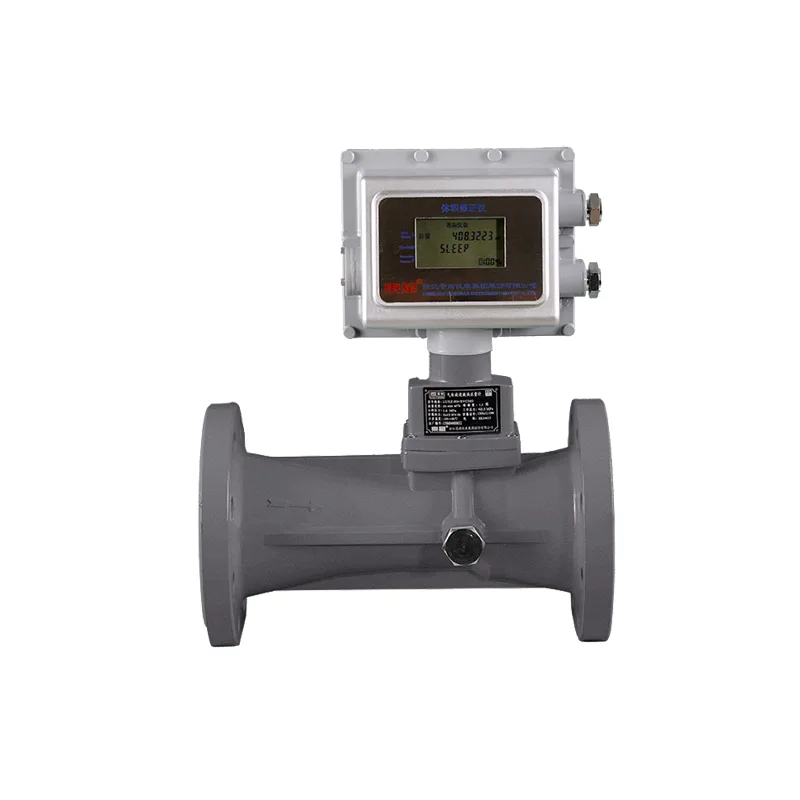
1.2This agreement applies to our factoryLWQZGas intelligent turbine flowmeter, LLQZIntelligent Roots flowmeter, LUXZIntelligent spiral vortex flow
Calculation, EVCVolume correction devices and other products.
1.3Main characteristics
Device attributes: The flow meter isMODBUSSlave stations on the communication bus
Communication mode: RTU
Communication media: RS485
mailing address: 1-247
Baud rate: 1200 , 2400 , 4800 , 9600 , 19200 bps
Data bits: 8Position
Checksum: No verification(2A stop position), Occasional verification(1A stop position), Odd verification(1A stop position)
1.4 specific characteristics
This agreement is developed for flow meters, Support multi byte binary numbers, ASCIIcharacter string, BCDData communication of code and other types of variables; Communication selectionMODBUSof Function code03H , 07HAnd add user-defined options, Function code66HSupported by.
Function codeMODBUSFunction code
The data frame format is as follows:, Function code:
2.1 Read the starting address at03: Rise upstart_addrIndividual character dataNSee table. Sent by the main station1.
Response from the station: addr, 03, start_addr_hi ,start_addr_low, N_hi,N_low, CRC
Abnormal response: addr, 03, num, data(0),… .,data(num- 1), CRC
Table: addr, 83H, error_code, CRC
Register address1
| Variable name | Number of registers | TypeN | Company | Accumulated operating conditions |
| 0000H | Accumulated quantity of standard conditions | 4 | BIN | |
| 0004H | Operating flow rate | 4 | BIN | Nm3 |
| 0008H | Standard flow rate | 2 | BIN | m3/h |
| 000AH | Temperature | 2 | BIN | Nm3/h |
| 000CH | Pressure | 2 | BIN | ℃ |
| 000EH | Among them | 2 | BIN | kPa |
starting address:
starting address: Fromstart_addr_hi , start_addr_low
2Composed of bytes, The high byte of the starting address in sequence, Low byte; The starting address must be the value in column 1 of Table 1, Otherwise, the flow meter will reply with an incorrect address(error_code =2); FromN_hi , N_low 2Composed of bytes, Read N words(1Data consisting of 2 bytes per character;
num : Indicate the number of data points, data(i) , i=0,…,num, num=2N.
error_codePlease refer to the table for the code4.
Example1 (Factory default: CodFor01 , CdrFor23 , bpsFor9600)
Sent by the main station: 17 03 00 04 00 04 073E
Address Function code Number of starting address registers CRCVerification code
Response from the station: 17 03 08 00000039412524E1 9D25
Number of bytes in the address function code Accumulated quantity of standard conditions Verification code
The variable data is a standard cumulative flow represented by an 8-byte binary number, High position first, The first 6 bytes are integer parts, The last two
One is the decimal part, Unpackaged data3752229. 144Nm3/h.
Please provide instructions for unpacking the attached data:
1) Integer part hexadecimal number00 00 00 39 41 25Equivalent to decimal system3752229.
2) Decimal hexadecimal numbers(24 E1) 16 = (9441)10 / 65536= 0. 14405(Decimal decimals).
3) The result is:3752229.14, Company: Nm3/h
Example2Read register data (in this example, read the data displayed by the current integrator)
send from the master station: 17 03 00 00 00 10 46F0
address function code number of starting address registers CRCchecksum
slave station response: 17 03 20 00 00 00 37 12 05 A0 43 00 00 00 37 12 05 A0 43
address function code number of received bytes operating condition cumulative quantity standard condition cumulative quantity
00 01 CB 6B 00 01 CB 89 00 00 14 00 00 00 65 53 BA 18
operating condition flow rate standard condition flow rate temperature pressure checksum
remark: when the data frame sent by the master station is incorrect, the slave station does not responderror_codecode, at this time, refuse the master to continue sending commands.
2.2 Function code07, Reading flow meters1Byte by byte status data. See table2.
Sent by the main station: addr, 07, CRC
Response from the station: addr, 07,status, CRC
Table2
| BIT7 | BIT6 | BIT5 | BIT4 | BIT3 | BIT2 | BIT1 | BIT0 | |
| 1 | There is a hardware malfunction | Low working condition flow alarm | High working condition flow alarm | Battery undervoltage 1 alarm | Battery undervoltage 2 alarm | Instantaneous flow rate Low | Pressing the button Operation | There is an external power source |
| 0 | No hardware malfunction | The operating flow rate is greater than the alarm low limit | The operating flow rate is less than the alarm high limit | The battery voltage is greater than the alarm limit1 | The battery voltage is greater than the alarm limit2 | Instantaneous flow rate Normal | No buttons | No external power supply |
2.3Function code66H, User defined function codes, Used to read historical data inside the flowmeter. See table3.
Table3
| Register address | Variable name | Number of registersN | Type | explain |
| 0063H | Record the starting time | 1 | BCD | Note:1 |
| 0064H | Current time | 3 | BCD | Note:2 |
| 0067H | Instrument production information | 18 | ASCII | Note:3 |
| 0079H | Real time recording | 17 | BCD/BIN | Note:4 |
| 008AH | Monthly records | 5 | BCD/BIN | Note:5 |
| 008FH | Start stop record | 8 | BCD/BIN | Note:6 |
| 0097H | Anti cutting record | 4 | BCD/BIN | Note:7 |
2.3.1Read the latest Mth real-time record(1Record entries)
Sent by the main station: addr, 66H, 00, 64H, 02H,M_hi, M_low, CRC
Response from the station: addr,66H ,22H,psum(BIN),sum(BIN),q0(BIN),t(BIN),p(BIN),year(BCD),month(BCD), day(BCD),hour(BCD),minite(BCD),sec(BCD), CRC
2.3.2Read the records from the past M months(1Record entries)
Sent by the main station: addr, 66H, 00, 65H, 02H, M_hi,M_low, CRC
Response from the station: addr,66H, 0AH, sum(BIN), year(BCD), month(BCD), CRC
2.3.3Read the latest Mth start/stop record(EVCNo start stop record, 1Record entries)
Sent by the main station: addr, 66H, 00, 66H, 02H,M_hi, M_low, CRC
Response from the station: addr,66H,10H,sum(BIN),year(BCD),month(BCD),day(BCD),hour(BCD),
minite(BCD),sec(BCD), ssflag(byte),0, CRC
2.3.4Read the record of the latest M-th sensor being cut or connected(1Record entries, Only applicable to intelligent integrators equipped with mechanical counters) Sent by the main station: addr, 66H, 00, 67H, 02H,M_hi, M_low, CRC
Response from the station: addr,66H,08H ,year(BCD),month(BCD),day(BCD),hour(BCD),
minite(BCD),sec(BCD), bkflag(byte),0, CRC
remarks:
MAs a character, Represented by 2 bytes, M_hiFor high byte, M_lowFor low bytes, When reading the latest record, M=1,
WhenM=0When it is greater than the number of records stored inside the flowmeter, The flow meter returns a sequence with a value of 0.
psum(BIN),sum(BIN): Accumulated quantity represented by 8-bit binary numbers, High position first, The first 6 bytes are integers, The last two
Byte is a decimal, Company: m3.
q0(BIN): Instantaneous flow rate under standard conditions represented by 4-byte 8-bit binary numbers, High position first, The first three bytes are integers, The last byte
For decimals; Company: Nm3/h.
t(BIN): Temperature represented by 4-byte 8-bit binary number, High position first, The first three bytes are integers, The last byte is a decimal; Single
Position: ℃.
p(BIN): Pressure represented by 4-byte 8-bit binary numbers, High position first, The first three bytes are integers, The last byte is a decimal; Single
Position: KPa.
year,month,day,hour,minite,sec
For single byteBCDCode, Representing the year (starting from year2000not displayed, 20month), day, hour, minute, second, marked as start/stop.
ssflagwhen, hourssflag=55Hmarked as start record, when; hourssflag=0EEHmarked as stop record, marked as normal/cut off.
bkflagwhen), Whenbkflag=55HTime, This record indicates that the sensor connection has been restored to normal; Whenbkflag=
0EEHTime, This record indicates that the sensor connection was cut off.
Note:1: Record the starting time: Used to specify the starting time for real-time recording, 2Bytes, Hour minute; The default second time is0;
Note:2: Current time: Year Month Day Hour Minute Second, 6Bytes, BCDCode, Among them, the year is 1 byte (starting from year2000not displayed, 20note): instrument production information3: byte: 36code, ASCIIincluding manufacturer code; word10product model, byte12product serial number 8 bytes, software version 3 bytes,
production date 3 bytes (year, month, day, note);
real-time record4: one real-time data record total
: byte34including cumulative quantity of working conditions 8 bytes, bit binary number(8unit, standard condition accumulation: m3 ), quantity 8 bytes bit binary number(8unit, instantaneous flow rate 4 bytes: m3 ), bit binary number(8unit, temperature: m3/h), byte4 bit binary system number(8unit, pressure 4 bytes: ℃), bit binary number(8unit, time 6 bytes: kPa), code( BCDyear, month, and year). Day, hour, minute, and second, note)
monthly record5: one month record in total;
bytes10cumulative amount of standard conditions 8 bytes, binary digits(8Binary digit, Company: m3 ), Time 2 bytes(BCDCode, Year
Month)
Note:6: Start stop record: A total of one start stop record15Bytes, Accumulated standard quantity of 8 bytes(8Binary digit, Company: m3 ), Six words of time Festival(BCDCode, Year Month Day Hour Minute Second), Start stop mark 1 byte(55HIndicating that traffic has grown from scratch, EEHIndicate the flow from presence to absence) , 0(Reserved bytes);
Note:7: Anti cutting record: One anti shear record consists of 8 bytes in total, Time 6 bytes(BCDCode, Year Month Day Hour Minute Second), Anti shear marking1 Bytes(55HIndicates that the sensor harness is connected, Under normal circumstances; EEHIndicates that the sensor harness has been cut off, For abnormal situations; record The time is the time when it is connected or disconnected), 0(Reserved bytes).
2.4 Several situations where the flowmeter does not respond after receiving a communication frame:
2.4.1When the communication address byte of the received data frame is different from the local address;
2.4.2The communication address byte for receiving a data frame (equal to0)when it is a broadcast address;
2.4.3when it receives a data frameCRCwhen there is a verification error;
2.5.4when the command code for receiving a data frame is incorrect.
2.5 when an exception is detected
when the slave receives a data frame sent to the local machine, CRCwhen the verification is correct, when an exception is detected,
the slave response is: addr, function_code+128,error_code,CRC
note: function_code: is the function code in the host command frame (the second byte), function_code+128the highest position of the byte
represents the exception1, table;
value4
| fault meaning | variable address is invalid |
| 02 | value is invalid |
| 03 | data type |
there are three types of data in the table
code and: BIN , BCDCode andASCIICode:
3.1 , BIN : Binary numbers, High byte first, Low byte after; There are four situations respectively:
1Byte (without decimals, unsigned);
2byte (without decimals, unsigned);
4byte (last 1 byte represents decimals, the highest bit of the first byte represents the sign bit, 1represents negative numbers, 0represents positive numbers). 8byte (last 2 bytes represent decimals, unsigned bits; the last 2 bytes represent decimals
one word after the decimal place of the real-time recorded cumulative quantity and standard cumulative quantity00, default).
3.2 , BCDdecimal place is calculated as one byte: 1code, byte represents two digits9.
3.3 , ASCIIvalue range is 0- : code, 8character, bitASCIIone byte, code.
represents one English letter or number
special instructions, compatible with the original custom flowmeter communication protocol:
4.1, adds a special instruction format, data bit is 8. no parity checkCodcommunication mode10.
4.2, set to(ADDR)flowmeter address023, factory default value is17.
4.3 , 02i.e. hexadecimal
4.3.1 , command to read measurement parameters:
55H, 55H, ADDR, 02 , 00, ChkSum
4.3.2, upper computer sends to flowmeter:
55H, 55H, ADDR, 02, 18, DevStatus, DevErr, Qm, Qo, t, p, sum, ChkSum
flowmeter responds to data frame to upper computer:
55H , 55Hremarks, Guiding characters for data frames;
ADDR Indicates the beginning of a data frame, 1Provide the communication address for the flowmeter, Bytes1—247.
02 Value range, 1For communication command number, Bytes.
18Read measurement parameters, 1For data length, Bytes18HIt indicates that there is something behind it.
Qm(A byte of data) , Qo(Operating flow rate) , t(Standard flow rate) , p(Temperature) , sum(Pressure).
ChkSum Accumulated quantity, 1To verify the sum, Its value is fromAddressUp toChkSumThe lower 8 bits of the sum of all previous data;
DevStatus : For status code, 1Bytes, The meanings of each of them are shown in the table5:
Table5
| BIT7 | BIT6 | BIT5 | BIT4 | BIT3 | BIT2 | BIT1 | BIT0 | |
| 1 | Command not Response | Qocall the police | Sleep | There is an external power source | Compression factor Sub compensation | There are buttons | Battery undervoltage | Low traffic |
| 0 | Command response | Qo Do not report to the police | Not sleeping | No external power supply | Not compensated | No buttons | The battery is normal | Normal traffic |
DevErr: For fault codes , 1Bytes, The meanings of each of them are shown in the table6:
Table6
| BIT7 | BIT6 | BIT5 | BIT4 | BIT3 | BIT2 | BIT1 | BIT0 | |
| 1 | Frequency circuit malfunction | Abnormal temperature sensor | Abnormal pressure sensor | A/DAbnormal conversion circuit | RAMFault | EEPROMFault | Serial port signal communication Fault | Clock circuit malfunction |
| 0 | The frequency circuit is normal | The temperature sensor is normal | The pressure sensor is normal | A/DThe conversion circuit is normal | RAMNormal | EEPROMNormal | Serial port signal communication Normal | The clock circuit is normal |
Operating flow rate, Standard flow rate, Temperature, Pressure is represented by a 4-byte (single precision) floating-point number, In sequence:P , SMH , MM , M
L, UseF (Float)express: FloatData = ±0.MH-MM-ML*2P
The cumulative amount is represented by a floating point number of 6 bytes, In sequence:P , SMH , MM , ML , ML1 , ML2, UseF (Float)express:
FloatData = ±0.MH-MM-ML-ML1-ML2*2P
Among them: P : Rank code, 1Bytes, Represented in hexadecimal complement format.
SMH : The high byte of the last digit, 1Bytes, The highest bit (7th bit) is the sign bitS , S=1 Indicates that the data is negative, S=0 Then the data is positive; The remaining 7 bits are the upper 7 bits of the floating-point number tail, Position 0 to 6.
MM : The middle byte of the tail, 1Bytes, 7th to14Position.
ML : The low byte of the tail, 1Bytes, The15Arrived23Position.
ML1 : The low byte of the tail, 1Bytes, The24Arrived31Position.
ML2 : The low byte of the tail, 1Bytes, The32Arrived39Position.
Example3:
The data frame sent by the upper computer to the flowmeter:
55 55 17 02 00 19
55H 55H ADDR CMD Len1 ChkSum
The data frame that the flowmeter responds to the upper computer:
55 55 17 02 18 15 00 00 00 00 00 00 00 00 00 05 50 00 00 07 65 4C CC
55H 55H ADDR 02 18 DevStatus DevErr Qm Qo t p
16 72 82 4A 49 25 E1
sum ChkSum
Divide the tail into integer and decimal parts using the decimal value of the order code as the boundary, Perform binary to decimal conversion calculations again.
Please provide a description of the attached data package:
55 55 17 02 18 ---
15
00
00 00 00 00 00 00 00 00 05 50 00 00
07 65 4C CC
Status code
Fault code
Instantaneous flow rate under working conditions=0
Instantaneous flow rate under standard conditions=0
Temperature=0.10100 000000000000000000×2∧0101=20
Pressure=0.1100101 0100110011001100×2∧0111=101.29998779
16 72 82 4A 49 25 Accumulated quantity=0.1110010100000100100101 00100100100100101×2∧10110 =3752229. 1428604125
E1 -- checksum
4.3.3 Floating point analysis of custom flowmeter communication protocol
Below is a detailed explanation on how to parse 4-byte floating-point numbers and 6-byte floating-point numbers.
Temperature: 05 50 00 00 According to the definition of data types, P=(05)H=(0101) 2 = 5
SMH=(50)H=(01010000) 2 MM=00 ML=00
. BecauseSMHThe highest position is0, Therefore, the tail number is positive. And the order code P is converted to a decimal number5, Therefore, after converting the tail number to binary, The first 5 digits are integer parts, The rest is the decimal part.
FloatData = 0 10100 0000000000 00000000 Convert to decimal number
Positive Integer part Decimal part
FloatData = 1×24 + 1×22 = 20
Stress: 07 65 4C CC Among them P=(07)H =(0111) 2 =7 SMH=(65)H=(01100101) 2 MM=(4C)H=(01001100) 2 ML=(CC)H=(11001100) 2
BecauseSMHThe highest position in the middle is0, Therefore, the tail number is positive, And the order code P is converted to a decimal number7, Therefore, after converting the tail number to binary, 7 bits are integer parts, The rest is the decimal part.
FloatData = 0 1100101 01001100 11001100 Convert to decimal number
Positive Integer part Decimal part
FloatData= 1×26 + 1×25 + 1×22 + 1×20 + 1×2-2 + 1×2-5 + 1×2-6
+ 1×2-9 + 1×2- 10 + 1×2- 13 + 1×2- 14 = 101.29998779
Accumulated quantity: 16 72 82 4A 49 25Among them P=(16)H=(00010110) 2 = 22 SMH=(72)H=(01110010) 2 MM=(82)H=(10000010) 2 ML=(4A)H=(01001010) 2 ML1=(49)H=(01001001) 2 ML2=(25)H=(00100101) 2 , SMHThe highest position in the middle is0, Therefore, the last digit is positive, And the order code P is converted to a decimal number22, Therefore, when the tail number is binary, have Bit is the integer part22The rest is the decimal part , Convert to decimal number.
FloatData = 0 1110010 10000010 0100101 0 01001001 00100101 Positive
Integer part decimal part decimal part
FloatData =1×221 + 1×220 + 1×219 + 1×216 + 1×214 + 1×28 + 1×25 + 1×22 + 1×20+ 1×2-3 + 1×2-6 + 1×2-9 + 1×2- 12 +1×2- 15 + 1×2- 17 = 3752229.1428604125


Leave a Reply