
1.3 Button Controls and Text Controls
This section mainly introduces the common applications of button controls and text controls in the Modbus protocol. Simple controls can be bound to variables, which can be associated on the configuration page or bound to variables in [Tools - Protocols and Variables - Logic Processing]
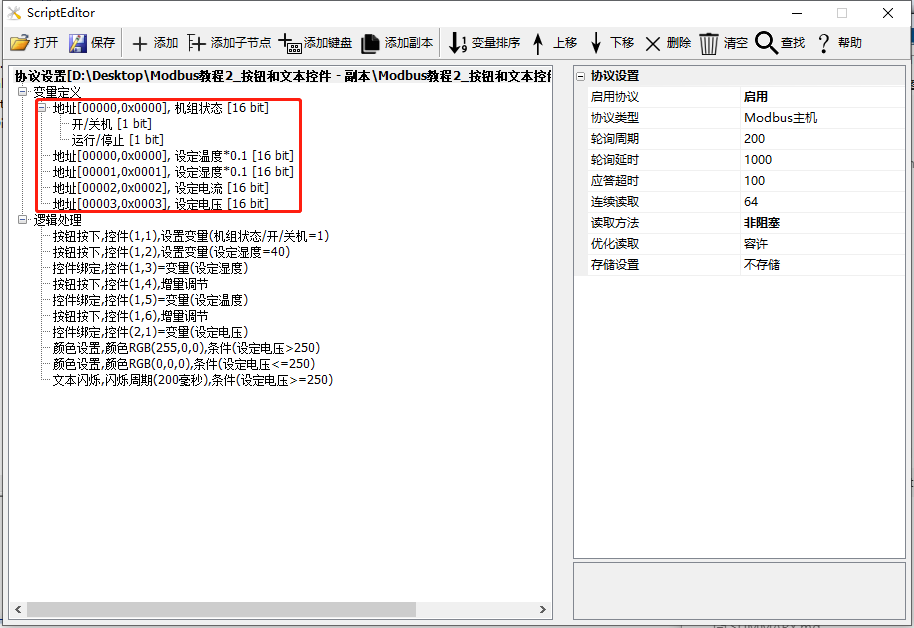
In this section, the screen acts as the master station, reading and writing slave device commands. If the screen acts as the slave station, the application of text and button controls is the same, and reference can be made. This section creates 2 coils and 4 save registers to illustrate the application of button controls and text controls, as shown below
Scope of Application: Full Series
Routine Download Link: "Modbus Tutorial 1_Getting Started V1.0" (click to jump)
For protocol activation and variable-related instructions, refer to the link: "Modbus Basic Parameter Description"
1.3.1 Button Controls
On the [Button Control] screen, when the button is pressed or released in the MODBUS protocol version, some preset logical operations can be executed
Screen/Logic Configuration
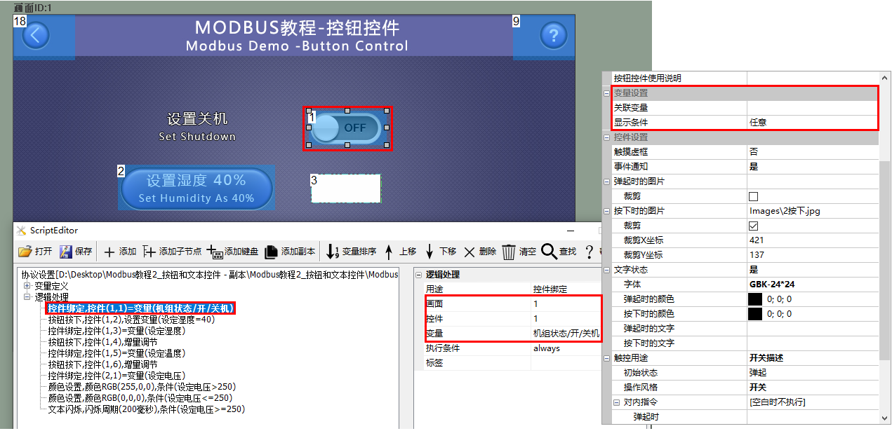
Set Shutdown
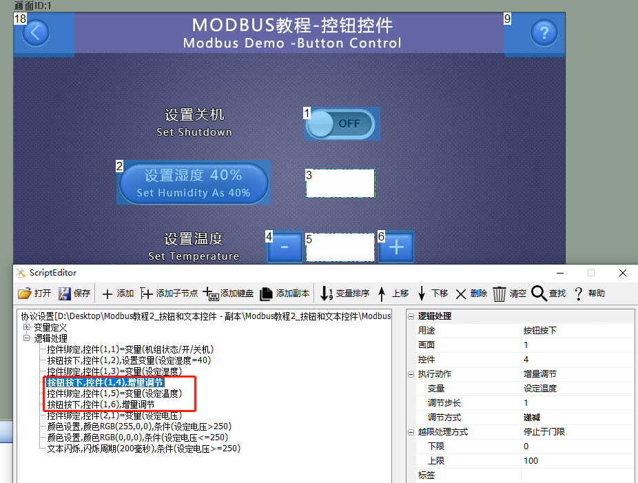
On the [Button Control] screen, for button control ID1, which is not directly associated with the control in the configuration interface, add the following logic processing
Add logic processing: For the purpose of [control binding], fill in the corresponding screen ID1 and button control ID1, with the variable being [unit status/on/off]
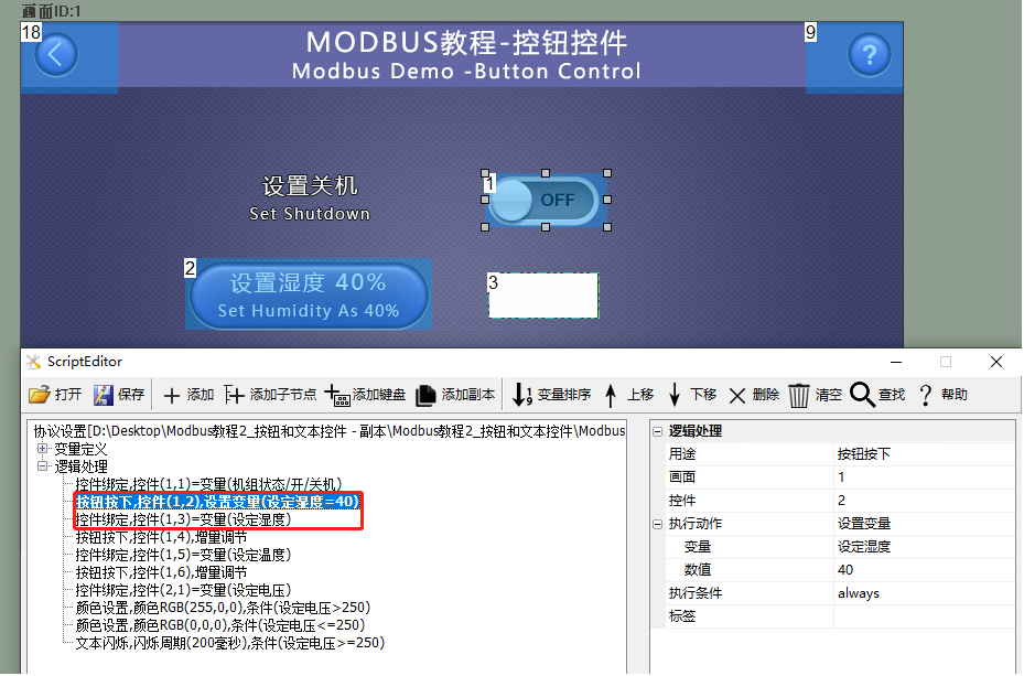
Set humidity to 40%
On the [Button Control] screen, button control ID2 and text control ID3, the configuration interface does not directly associate with the controls. Add the following logic processing
Article 1: Purpose: For [button press], fill in the corresponding screen ID1 and button control ID2. The execution action is [set variable], and set [set humidity] to 40
Article 2: Purpose: For [control binding], fill in the corresponding screen ID1 and text control ID3. The variable is [set humidity], and the bound variable is also [set humidity]
as shown below:
Set Temperature
On the [Button Control] screen, for button controls ID4 and ID6, and text control ID5, the configuration interface does not directly associate with the controls. Add the following logic processing
Article 1: Purpose: For [button press], fill in the corresponding screen ID1 and button control ID4. The execution action is [incremental adjustment], the variable being adjusted is [set temperature], the adjustment step size is [1] (step size can only be an integer), and the adjustment method is [decremental]
Article 2: Purpose: For [control binding], fill in the corresponding screen ID1 and text control ID5, with the bound variable being [set temperature]
Article 3: Purpose: For [button press], fill in the corresponding screen ID1 and button control ID6. The execution action is [incremental adjustment], the variable being adjusted is [set temperature], the adjustment step size is [1] (step size can only be an integer), and the adjustment method is [incremental]
as shown below:
Run Preview
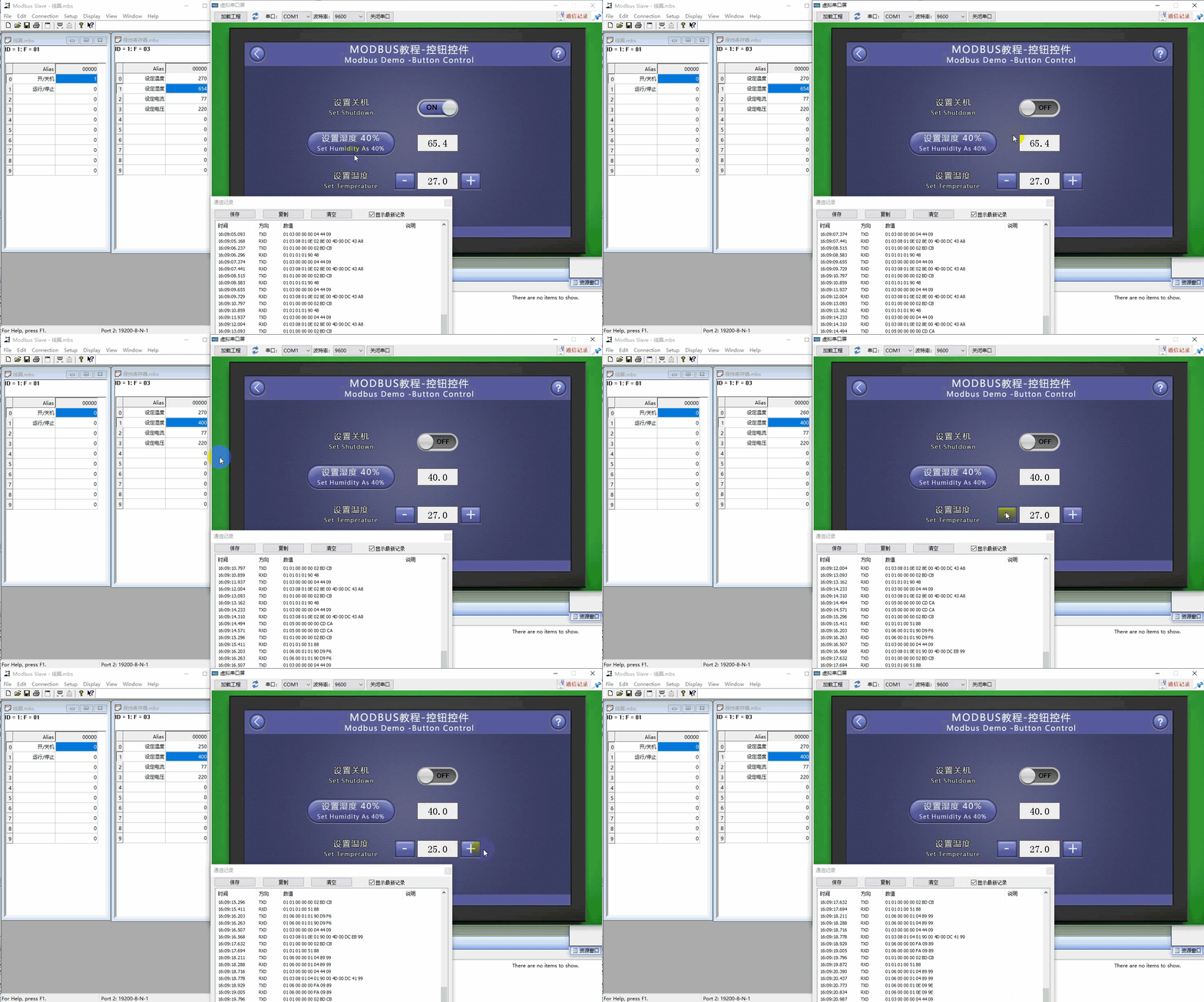
Based on the screen configuration and logic processing, combined with the modbus slave debugging tool, when the button control (control ID: 1) is pressed, the state of the slave device is set to off. Similarly, when the button is pressed, it can also be used to save the variable settings of the register, perform incremental adjustments, and other functions. The operation results are shown as follows
1.3.2 Text Control
In the "Text Control" interface, the text control is primarily used to display the bound variable values. For variables of read-write types such as coils and hold registers, the "Input Method" can be set to pop up a system keyboard for input, allowing modification of the bound variable values through the popped-up keyboard. Additionally, it is possible to bind logic processing for modifying display colors and blinking
Screen/Logic Configuration
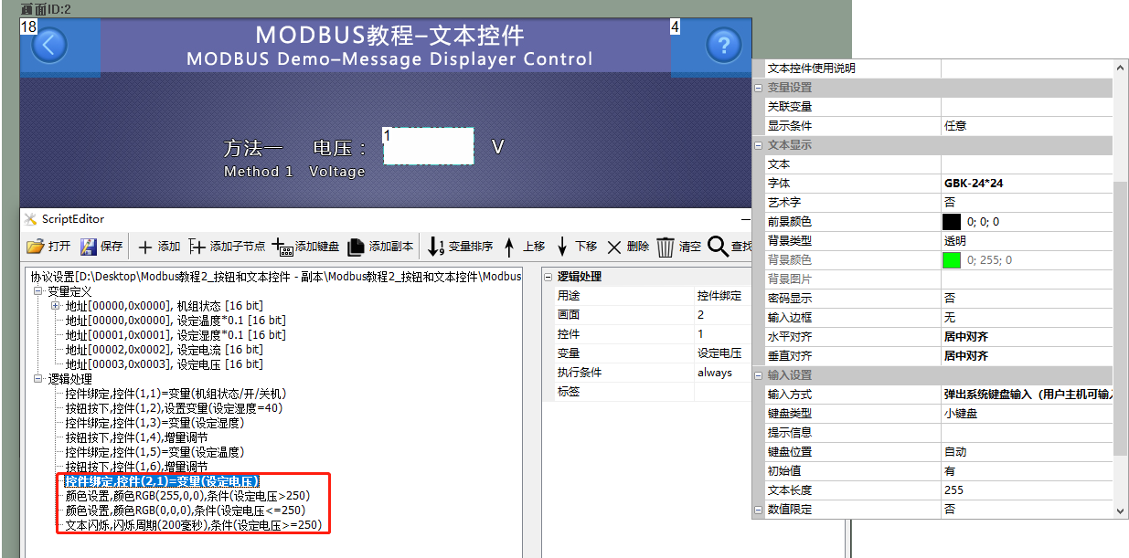
Add a text control (control ID: 1) to the screen to display the voltage value; the input method is a pop-up keyboard. Add the following logic processing:
Item 1: Purpose is "Control Binding", binding variable "Voltage"
Item 2: Purpose is "Set Color", set the color to red (RGB (255, 0, 0)), with the execution condition being that the value of "Set Voltage" is greater than "250"
Item 3: Purpose is "Set Color", set the color to black (RGB (0, 0, 0)), with the execution condition being that the value of "Set Voltage" is less than or equal to "250"
Item 4: Purpose is "Text Blinking", with the execution condition being that the value of "Set Voltage" is greater than "250"
Run Preview
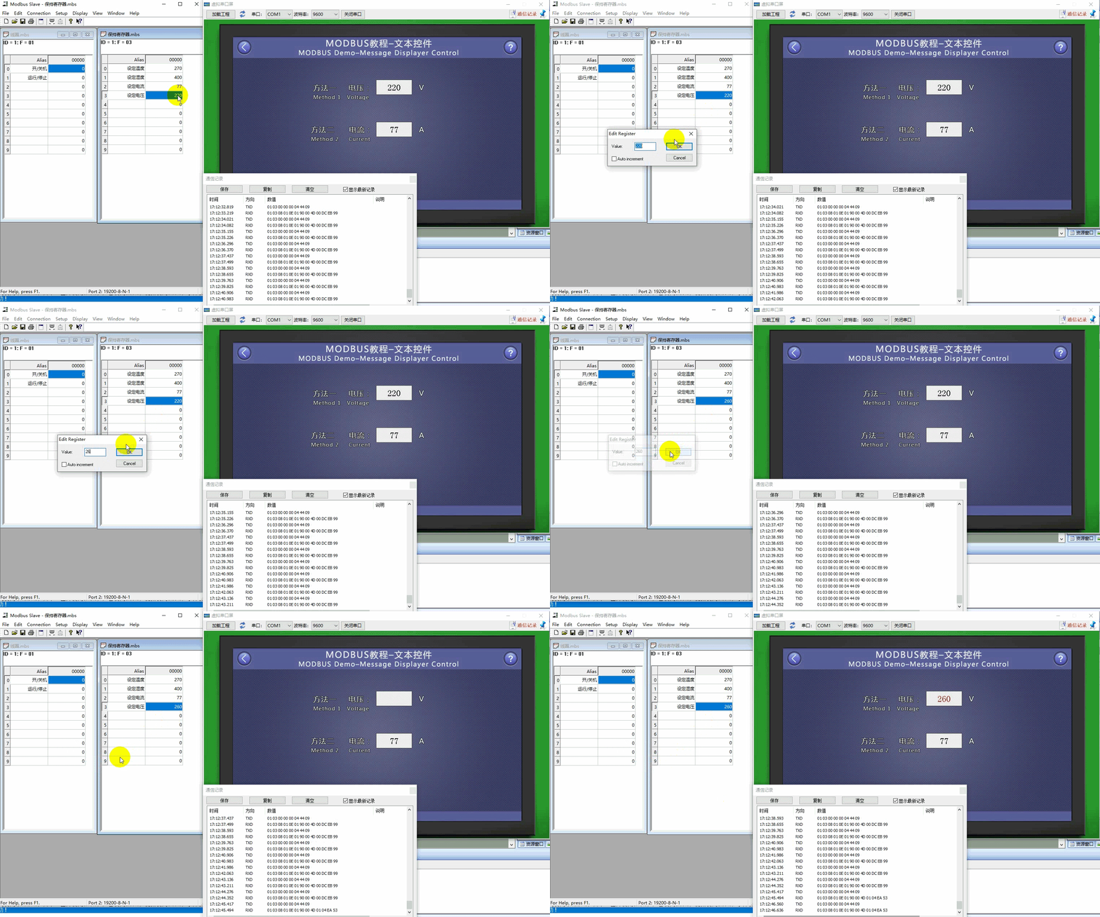
Display the current and voltage values in real time. When the "Voltage" value is greater than 250, the text displays in red and blinks; if the "Voltage" value is less than or equal to 250, the text displays in black and does not blink, as shown below:


Leave a Reply