
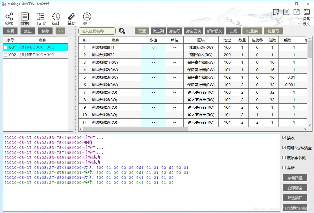
MTings is a new standardized professional MODBUS debugging tool that provides integrated master-slave operation and can be used for debugging and testing of MODBUS protocol interfaces, as well as Modbus device operation and maintenance. It mainly solves the following problems:
3.8 Writing Data (Host Device)
simulationModbusEquipment Software, SupportModbusPassive read and write function of slave machine.
Support multiple devices, Multi channel concurrent operation, No limit on the number of devices.
Support persistent data configuration, No menu design, User friendly operation.
SupportMODBUS-RTU, MODBUS-ASCII, MODBUS-TCP.
Support serial port, TCPclient, TCPServer (Can access multiple clients) , UDPunicast.
Support full link message monitoring, storage, Analyze.
Support rich link packet loss statistics methods.
Support data curve recording, Extreme and mean values of statistical data, And can export all data.
SupportMODBUSImport and export of data configuration templates.
Support multiple simulation methods for variable data.
Support secondary processing of data, The interface presents the original real data.
Support good non-standard protocol adaptation.
excellent performance, Support access > 500Device Node, super20Kdata point.
Permanent free, portable, Chinese.
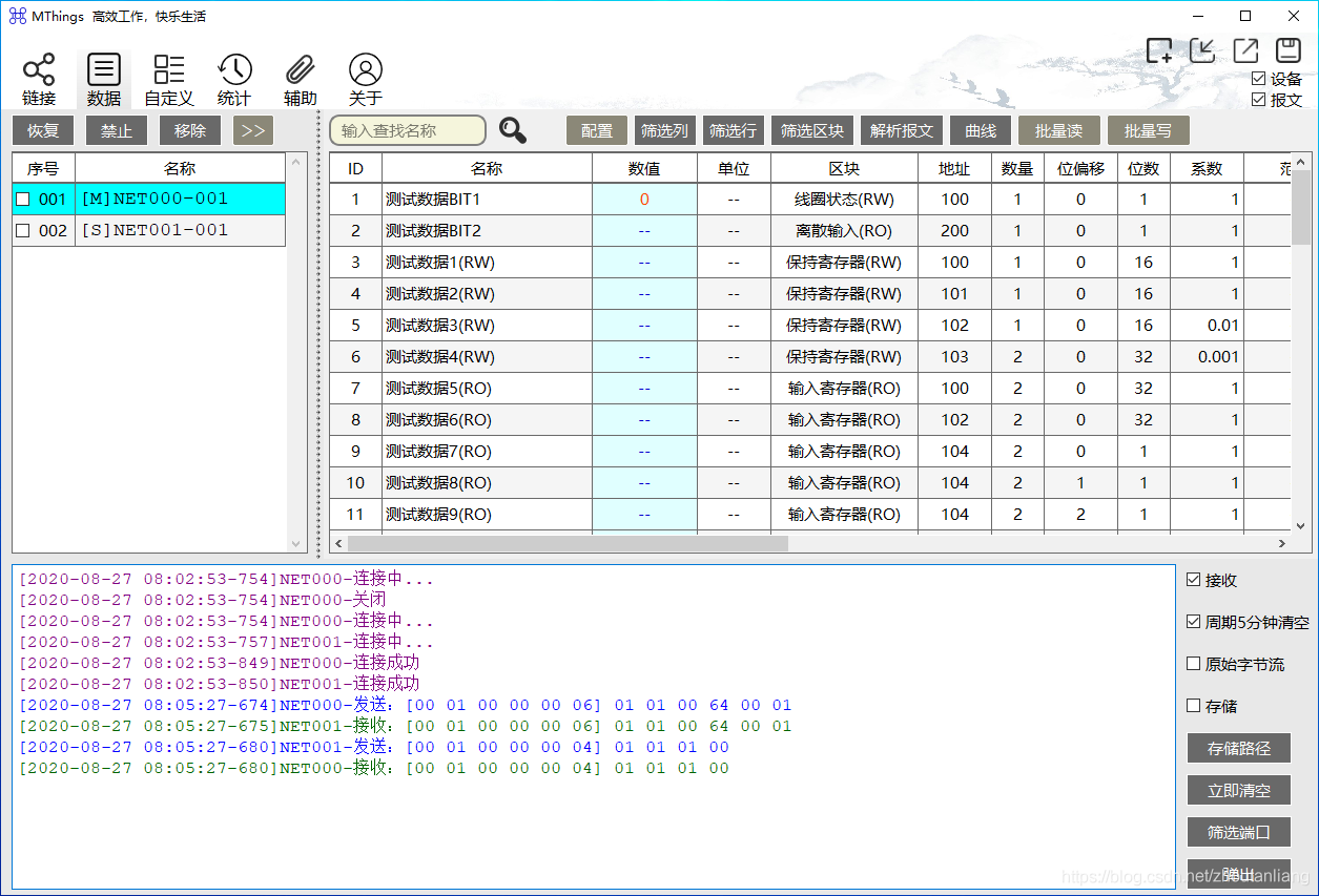
2.data
MODBUSThe protocol is a relatively simple bus protocol, The interaction process and message agreement areModbus Application Protocol V1_1b3Clear answers can be obtained in the middle. Here, I would like to explain my personal understanding of data blocks and data definitions that often cause ambiguity.
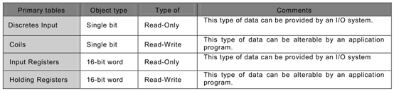
2.1 data block
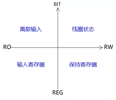
Four types of data blocks are defined in the protocol, Based on data types, it can be divided into two categories: BITdataAndregister data, Combining read-write attributes, The relationship between data blocks is shown in the following figure:
2.2 data
Data is a detailed definition of specific information within a data block, The data definitions in different data blocks are independent of each other. A data definition can contain multiple consecutive dataBIT/REGdata point.
The attributes that describe data mainly include:
@Subordinate data block
@data name
@data address
@data volume
@data type (Protocol Type)
@Data coefficient (Floating point data involved in shaping transmission)
@endianness (Register data involves)
@Word order (Register data volume≥2Wordinvolve)
@Within the same data block, The data addresses and data volumes defined by different data cannot overlap;
@The data of any data block is readable and writable on the slave side;
@The data in different data blocks can point to the same data object on the slave side, It has two different data block addresses, The difference lies in opening up different read and write permissions through this difference;
@REGThe minimum amount of data is1, The maximum value shall not exceed the upper limit (input register: 125, holding register123) ;
@BITThe fixed amount of data is1, Representative occupation1Bit, Simultaneously, the data coefficient attribute is invalid;
2.3The relationship between data blocks and data
@Within the same data block, The data addresses and data volumes defined by different data cannot overlap;
@The data of any data block is readable and writable on the slave side;
@The data in different data blocks can point to the same data object on the slave side, It has two different data block addresses, The difference lies in opening up different read and write permissions through this difference;
@REGThe minimum amount of data is1, The maximum value shall not exceed the upper limit (input register: 125, holding register123) ;
@BITThe fixed amount of data is1, Representative occupation1Bit, Simultaneously, the data coefficient attribute is invalid;
2.4transmissionTypes and presentation types
The protocol data definition method is mainly based on transmission design, It andUIThere is inevitably a problem of mutual conversion between data, Including types, Length, Functional Differences.
MThingsProvide user-friendly data visualization methods, Support displaying message data in actual business format.
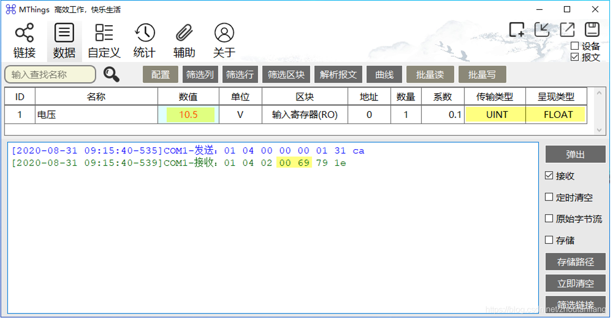
The transmission type isMODBUSTypes defined in the data protocol, Usually, plastic surgery is the most common method, But often it is not in the actual format of the data, The user needs to recalculate in order to confirm the correctness of the data. Insufficient intuitive debugging data undoubtedly seriously affects debugging efficiency and accuracy.
MThingsSupport users to specify the transmission and presentation types for each data item, During the debugging process, Software automatically converts according to configuration, The data presented on the interface will be the true content of the data.
for example, Report voltage data from the slave machine10.5V, During the register transfer process, the data is0X0069, MThingsAfter receiving the data, Multiply the shaping data by a coefficient0.1, The interface presents the restored data10.5V.
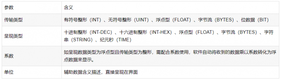
When entering data configuration, MThingsThe provided parameters include transmission type, Presentation type, coefficient, Four configurations of the unit, Their meanings are respectively:
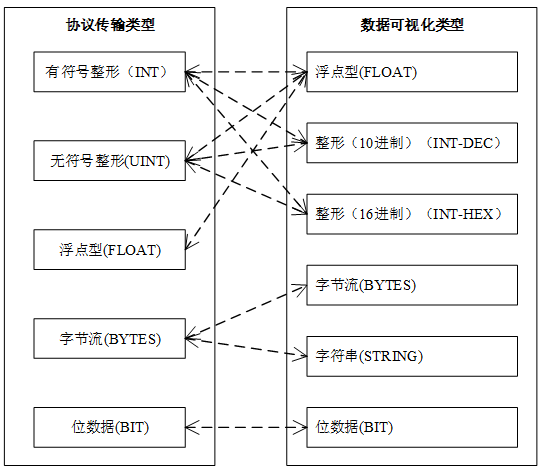
MThingsSupports multiple protocol transmission types andUIdata type, The corresponding relationship is as follows:
3 Feature Introduction
3.1 Interface partitioning
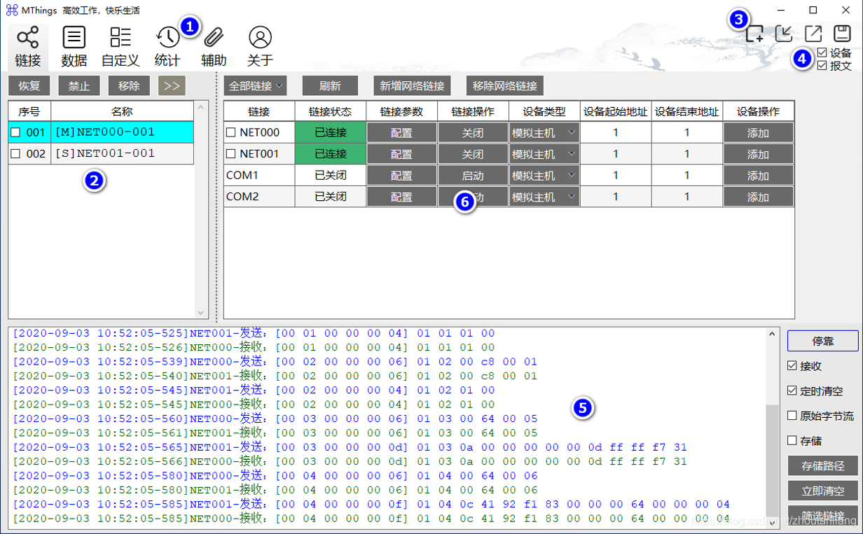
- 1.Main Menu: Used for switching“Main function page”.
- 2.Device List: Assistant“Main Menu”, Users click on the device name, Can switch the currently activated device, Specify a new one“Main function page”Associated device.
- 3.configuration file: Used for creating new, Import, Save As, Save configuration file.
- 4.View Switch: Used to control display or hide“Device List”And“Message Monitoring”window.
- 5.Message Monitoring: View and manage communication messages of various links.
- 6.Main function page: correspond to“Main Menu”, Provide the main function operation interface.
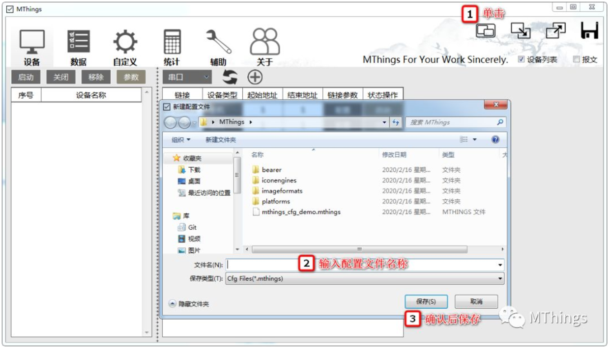
3.2 Create a new work configuration file
Note:If no other configuration files are loaded at the beginning stage, You can skip this step, Click save before exiting the program to create a configuration file.
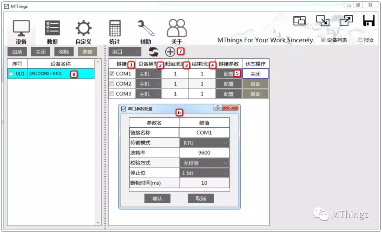
3.3 Create serial device

- 1.Check the serial port on which the new device is attached (Double click on the header to select all)
- 2.Select the type of device to be created
- 3.Enter the starting address of the device
- 4.Enter the end address of the input device
Note:starting address ≤ End Address, If the starting and ending addresses are the same, it means adding a device, Program based on specified start to end addresses, Automatically create a device for each address within the interval.
- 5.Click“Configuration”, Confirm or modify serial port parameters
- 6.View or modify serial port parameters
- 7.After clicking, the program starts adding devices
- 8.After the device is successfully added, You can view the device here.
Note:Default format for device name: [M/S]Port Name Address, Users can double-click the device name cell to modify it themselves, But it is necessary to ensure that the new name does not conflict with other device names, Otherwise, the name modification will fail.
Note:Within the same port/link, Not allowed to add devices of different types.
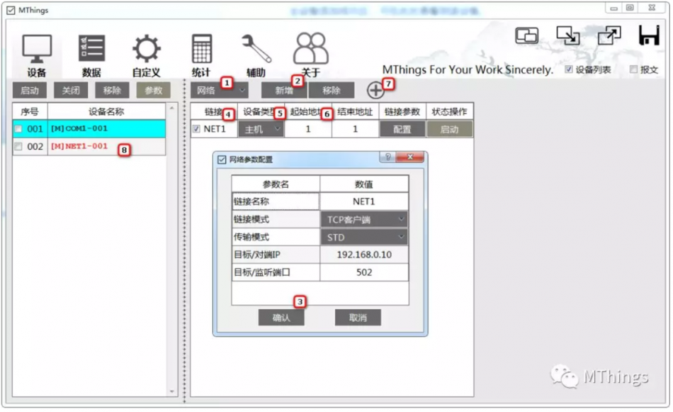
3.4 Create network devices
- 1.Switch port type to“Internet”
- 2.Click“Create”button, Add a new network configuration
- 3.After confirming or modifying the network configuration, click“Confirm”, Add a new link corresponding to the network port table
- 4.Check the network link on which the new device is attached
- 5.Select the type of device to be created
- 6.Enter the starting and ending addresses of the device
- 7.Click to start adding devices
- 8.After the device is successfully added, You can view the device here.
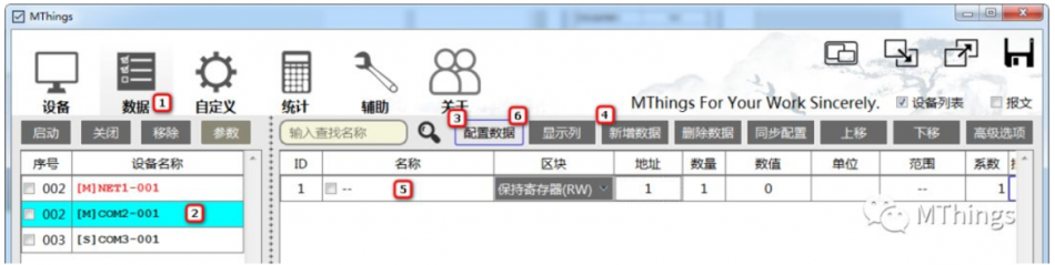
3.5 Edit device data configuration
- 1.Click on the main menu“data”, Switch to the device data operation interface
- 2.Click on the device that requires data configuration
- 3.Click“configuration data”The button causes the current device to enter data configuration mode
- 4.Click“Add data”Button to create a new data configuration item, Add a default configuration synchronously in the data table
- 5.Modify various parameters in the data configuration items
Note:During the modification process, the program will automatically associate parameter changes, Please carefully confirm whether all parameters are correct.
- 6.Click the button to exit the data configuration mode
Note:Before exiting the configuration mode, the program will verify whether the final configuration result is correct, If there is a conflict in the data address, Please modify according to the prompts, Otherwise, it is not possible to exit the configuration mode.
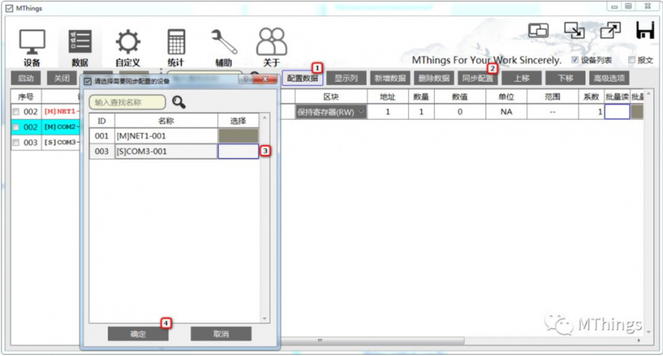
3.6 Synchronize data configuration to other devices
For the convenience of configuring data across multiple devices, The program supports configuration sharing between different devices.
- 1.On the source device (Data configuration sharing) Click the button to enter the data configuration mode
- 2.Click“Synchronization configuration”
- 3.Specify the target device for configuration synchronization
- 4.Click“Determine”Start configuring synchronization after pressing the button
3.7 Read data (host device)
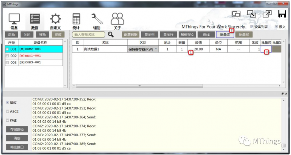
There are two ways to read data:
1.long press (>300ms) Numerical column cell, The program automatically initiates data once (current line) Read request
2.Click“Batch reading”, Initiate multiple data read requests at once (Batch read configuration items③Selected) , Users can also initiate a cyclic batch read according to the prompts.
3.8 Write data (host device)
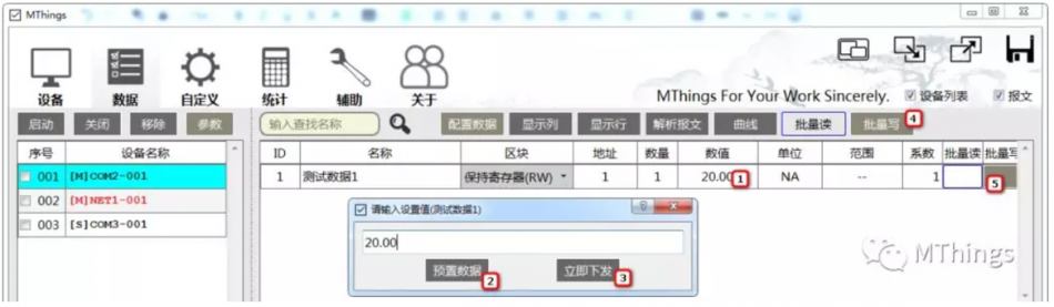
There are two ways to write data:
- 1.double-click“numerical value”Column data cell, Initiate a write request for a single data; A single data write request is divided into preset data
- 2.Or issue it immediately
- 3.Click to publish immediately, The program immediately initiates a data write request, And automatically follow a data read request once, If the data write request is successfully executed, The data in the cell is the issued write data. Pre set data operation is to pre-set target data in advance for batch write operations.
- 4.Click“Batch writing”, Initiate multiple data write requests at once (Batch write configuration items⑤Selected) , Users can also initiate cyclic batch writing based on prompts.
3.9 Configure simulated data (slave device)
The data from the slave device is mainly used for the host to read, It's for simulating data.
The method of modifying simulated data is very simple, double-click“numerical value”Column data cell, Just enter the corresponding numerical value.
If it is necessary to store the simulated data set in the configuration file, Need to click“configuration data”button, After entering the device data configuration mode, simply modify the data values.
3.10 Exit the program
Before the user closes the program, The program automatically checks whether the configuration has changed during use, And provide storage prompts, So please pay attention to the prompt message that pops up when the program exits, And provide the correct choice.
4 data configuration
Data configuration is carried outMODBUSThe essential steps for reading and writing operations, Fast, efficient, and accurate completion of data configuration is a prerequisite for debugging work.
4.1 Start data configuration
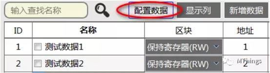
Enter the data interface of any device, click“configuration data”button, The current device has entered data configuration mode. After entering configuration mode, MThingsForce display of all configuration data, Including manually hidden configuration lines, And it is not allowed to hide any configuration information in the configuration state. After entering configuration mode, MThingsAutomatically shut down all current devices that are engaged in background communication, After configuration is completed, Manual recovery is required.
4.2 New Data Configuration
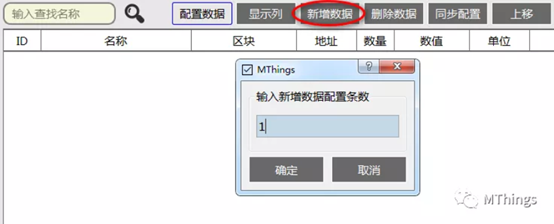
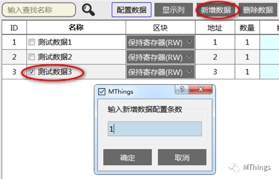
click“Add data”button, The dialog box that pops up later allows you to specify the number of new configurations to be added. Newly created configuration data is added to the end of the table by default, Users can access“Move up”Or“Move down”Button controls the up and down movement of one or more rows of configurations.
MThingsSupport creating new configurations using existing configurations as templates, click“Add data”Before the button, Select the data configuration row for reference. If no data configuration row is selected, MThingsDefault selection of the last line for new configuration template.
4.3 Modify data configuration
Modifying data is the most important step, MThingsProvide multiple automatic association actions and verification functions, Assist users in accurately completing data configuration.
Usually, according toMODBUSThe data definition of the protocol point table is entered with the data name separately, Data Block , data address, data volume, unit, scope, coefficient, display type, Transmission Type, endianness, Word order, Double click to edit regular cells.
among which, The data volume of register data is the number of registers, BITThe fixed amount of data is1.
The transmission type is protocol defined type, The original data type in the message.
Display type as expected data inMThingsThe target type parsed on the interface.
Data transmission type, The display type and other fields will vary according to the changes in other fields, Automatically match selectable items, Non matching types will be disabled.
Coefficient used for shaping data (Transmission Type) And floating point type (display type) mutual conversion, In other scenarios, Fixed as1. Example: The coefficient is set to0.1, The original transmission data is123, The interface displays the data as12.3.
4.4 Association rules for data configuration items
1) BITTyped Data, The fixed amount of data is1, The transmission type is fixed asBIT, The data coefficient is fixed at1, endianness, Word order prohibited as invalid;
2) Register type data, Transmission type prohibitedBIT;
3) The input register data amount does not exceed125;
4) Keep the amount of register data not exceeding123;
5) When the transmission type is floating point type, The coefficient is fixed at1;
6) When the data volume is 1, Transmission type prohibits floating point type;
7) The amount of data is not1At 2 and 4 o'clock,Transmission type prohibits all shaping;
8) When the transmission type is integer or floating-point, Byte order and word order can be configured, Otherwise disabled;
9) The amount of data is2At 4 o'clock,Word order can be configured, Otherwise disabled;
10)The current display type is string(STRING)Or code stream (BYTES)At that time,This data does not support curve drawing;
4.5 Exit configuration mode
click“data configuration”button, MThingsCheck if all data configurations are legal, If the inspection passes, The current device returns to operational mode, Otherwise, it will prompt an abnormal configuration, And provide the reason for the abnormality.
4.6 How to be more efficient
Use the configuration synchronization function, After editing the configuration of a device, Synchronize the current configuration with other devices that have the same point table; Borrowing existing data configuration templates to add new data configurations;
Precautions:
1, Monitor resolution for running computer: 800*600Or higher, Recommend using resolution19201080. SupportWin7Version and above, compatible32/64Position.



谢谢分享
谢谢
Good
666
good
xiazai ba
谢谢
Download
学习学习
学习学习
666
6666
试试看好用不
6666
666
6666
试试
软件介绍的很详细,功能完整。
666
666
试试
hhdfdffjkioom;[[
666
看下好不好用
666
666
666
666
谢谢分享 很好用
不错!
非常好,正常调试这块,有个工具太方便了
good
666