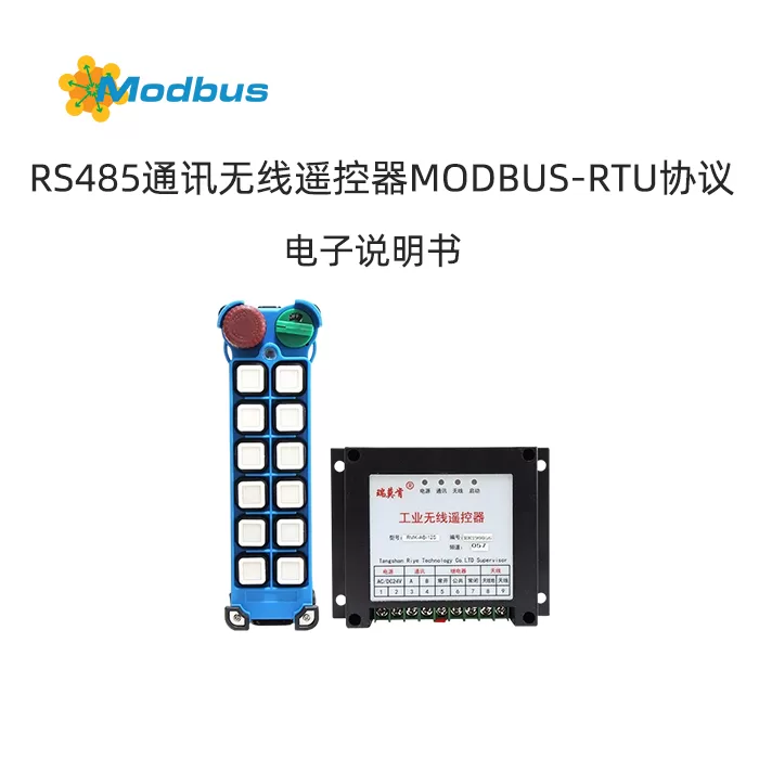
485 Industrial Wireless Remote Control System
Professional Wireless Control Solution, Supporting ModBus Communication and Customized Functions
I. System Composition
| Components | Type and Function Description |
|---|---|
| Transmitter | Handheld (Multi key) or Backpack (with joystick speed adjustment) |
| Receiver | Model:485 Communication Type - Output Method: Relay Output (Total Stop Signal)+ModBus RTU RS485 - Installation Method: Cabinet Rail Installation - Dimensions: 115mm × 90mm × 40mm - Power Supply: AC/DC 24V (without distinguishing positive and negative poles) |
| Antenna | External Extension Antenna to Enhance Signal Stability |
| Configuration Storage | DedicatedE-Card(storing serial numbers, channels, button functions, etc.) |
II. Core Functions
- Communication Protocol
- SupportModBus-RTU RS485Communication, compatible with PLC/upper computer.
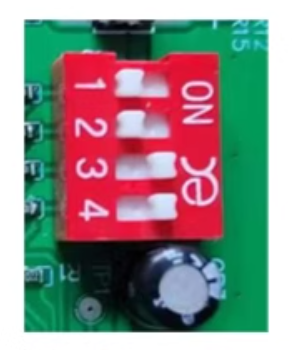
- Baud rate9600/38400/57600/115200bps (set by dip switch).
- slave address1~4 (set by dip switch).
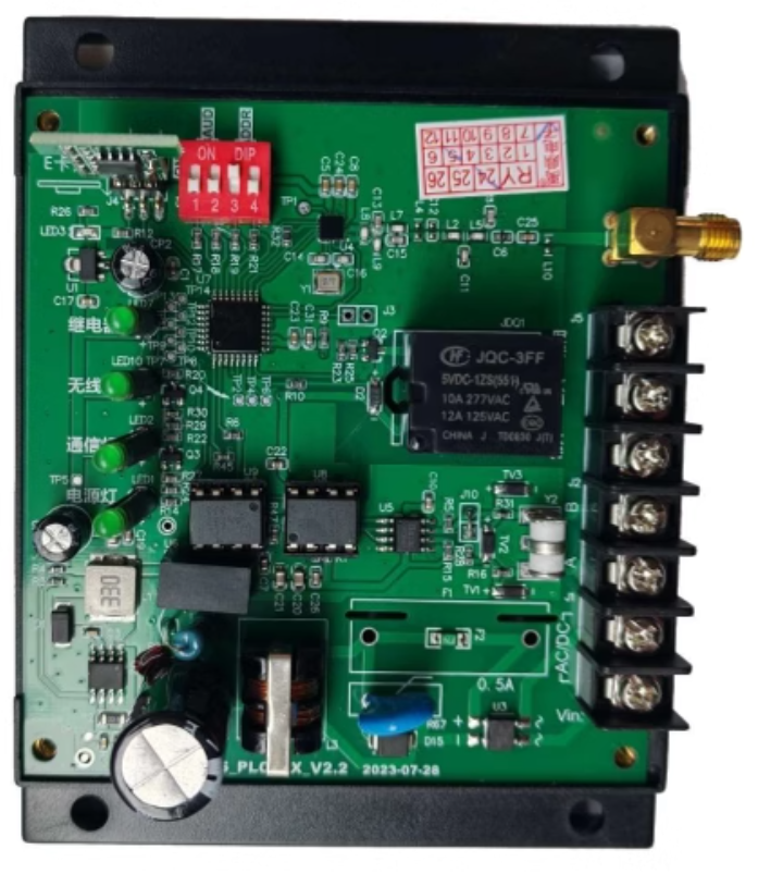
- Dial switch setting(Red 4-position switch inside the receiver) Switch position function setting instructions1+2Baud rate ON+ON: 9600 → ON+OFF: 57600
OFF+ON:38400 → OFF+OFF:1152003+4Communication address ON+ON: 1 → ON+OFF: 2
OFF+ON:3 → OFF+OFF:4
- Key function configuration
- Maximum support24 buttonsThe functions are stored on the E-card, such as start stop, speed regulation, and custom logic.
- supportsenergy-saving settings, startup mode, shutdown time and other parameter configurations.
- Customization Extension
Can provide special function customization:
✅ Chain Logic ✅ Analog control ✅ Feedback display
✅ CAN communication ✅ TCP communication ✅ RS485 Integration
III. ModBus Register Mapping Table
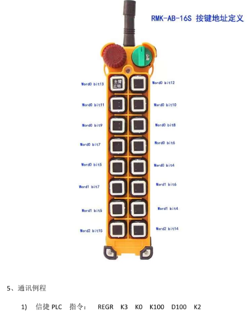
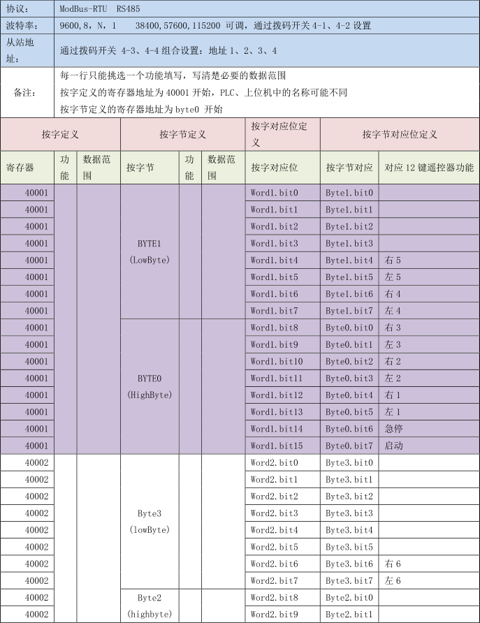
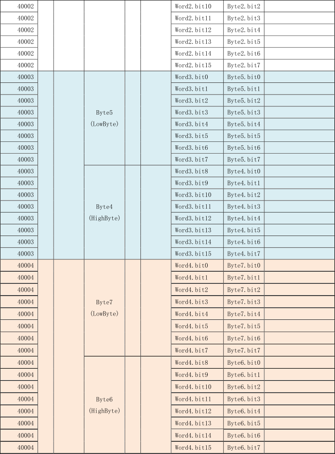
Data Address Definition(Taking12 Key Remote Controlas an Example):
- Start Register:
4x0001(Word Mode) orByte0(Byte Mode) - Button State Mapping Relationship:
Button Function Word Mode Bit Address Byte Mode Bit Address
Button 1Word0.bit13Byte1.bit5
Button 2Word0.bit12Byte1.bit4
… … …
Button 16Word2.bit15Byte3.bit7Key Description:- Each register (such as 40001) contains16 bits(bit0~bit15), corresponding to 16 button states.Bit value=1: Press the button;Bit value=0: Press the button to release.

- 2. PLC Communication Example
- Xinjie PLC instruction:
REGR K3 K0 K100 D100 K2
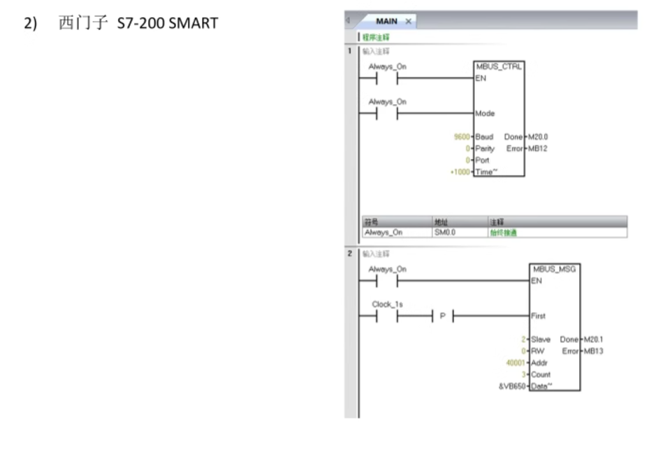
(meaning: from station address 3, read registers 40001-40002 to D100~D101)Siemens PLC: Need to parse the bit state ofByte0~Byte3(refer to the mapping table).
- Xinjie PLC instruction:
- V. Technical ParametersProject Parameters Operating Voltage AC/DC 24V ± 10% Wireless Protocol LORA/GFSK/2.4G/5G Channels 255 Independent Channel Serial Number Capacity 4 billion groups (anti-interference) Protection Level IP65 (industrial dust and water resistance)VI. Service Support
- Custom requirementsProvide deep customization of logic control, communication protocol integration, display feedback, and more.Technical Support: Contact the manufacturer to obtain configuration tools and complete register definition tables.


Leave a Reply