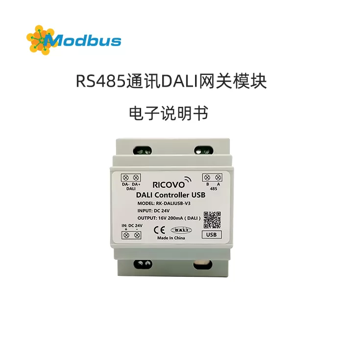
I. Product Overview
Model: RK-DALI USB-V3 Gateway
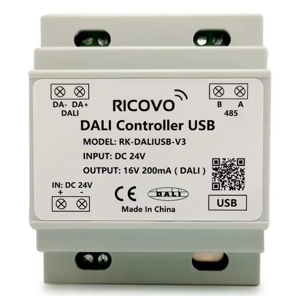
Communication Port:
- USB: Connect to a computer and use the upper computer software (DALIController) to configure DALI devices.
- RS485: Communicate with the main control device (simplex bidirectional), support sending DALI commands, and query device status.
- DALI: Control DALI lighting equipment (only 1 port, fixed port number
1).
II. Communication Parameters
| Parameters | Value |
|---|---|
| Baud Rate | 9600 bps |
| Data bits | 8-bit |
| Stop bit | 1 |
| Check bit | None |
| Instruction interval | ≥ 100 ms |
III. Protocol frame format
| field | Byte position | Length | Description |
|---|---|---|---|
| Baotou | 1-2 | 2 | fixed value0x1A 0xCC |
| gateway address | 3 | 1 | scope1-254(Default)0x01) , 255For broadcasting addresses |
| DALI port | 4 | 1 | Value 1(Only 1 port) or255(All ports) |
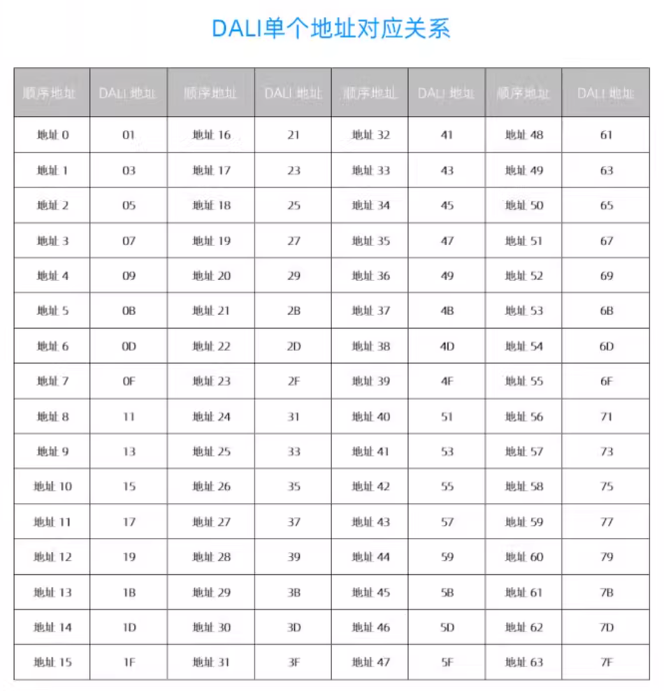
| DALI address | 5 | 1 | - Short URL: 0x00(Address 0)~0x7E(Address 63)- Group Address: 0x80(Group 0)~0x9E(Group 15)- broadcast address: 0xFE/0xFF |
| function code | 6-n | variable | Control/query instructions (see below for details) |
| Bag tail | n+1 | 1 | Fixed Value0x0F |
IV. Instruction Explanation
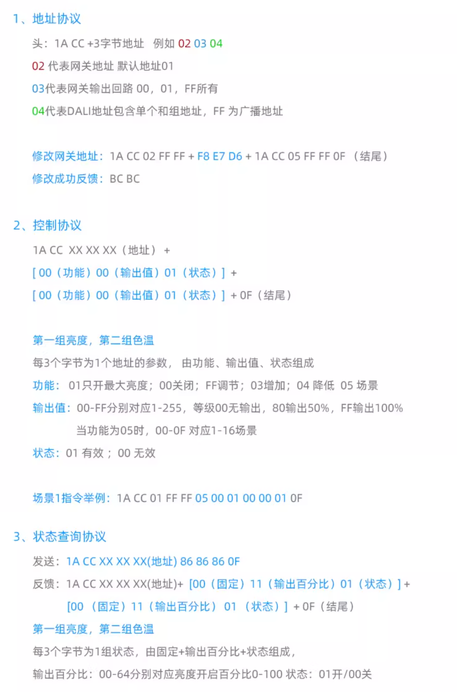
1. Modify Gateway 485 Address
Send Instruction: 1A CC XX FF FF F8 E7 D6 1A CC YY FF FF 0F
XX: Original Address (e.g.0x01)YY: Target Address (e.g.0x02)
Successful Response:BC BC
Example(Modify Address
0x01→0x02):1A CC 01 FF FF F8 E7 D6 1A CC 02 FF FF 0F
2. Control Instruction
Common Format: 1A CC [网关地址] [DALI端口] [DALI地址] [功能组1] [功能组2] 0F
- functional group: composed of
功能码+输出值+状态(grouped every 3 bytes). - Status bits:
0x01(enabled),0x00(invalid).
| Function | Function Group 1 Configuration | Function Group 2 Configuration | Description |
|---|---|---|---|
| Dimming+Color Temperature | FF [亮度值] 01 | FF [色温值] 01 | Brightness Value0x00(Off)~0xFE(100%)Color temperature value 0x00(2700K)~0xFF(6500K *) |
| Individual dimming | FF [亮度值] 01 | FF 00 00 | Adjust brightness only |
| Individual color temperature | FF 00 00 | FF [色温值] 01 | Adjust color temperature only |
| Turn off (OFF) | 00 00 01 | FF 00 00 | Immediately turn off |
| Maximum brightness | 01 00 01 | FF 00 00 | Immediately switch to maximum brightness |
| Brightening (UP) | 03 00 01 | FF 00 00 | Gradient dimming (approximately 200ms) |
| Dimming (DOWN) | 04 00 01 | FF 00 00 | Gradient dimming (approximately 200ms) |
| Call scenario | 05 [场景号] 01 | FF 00 00 | Scene number0x00~0x0F(Scene 0-15) |
Example(Gateway address)
0x01, DALI address0x04, brightness 100%+color temperature 3000K):1A CC 01 01 04 FF FE 01 FF 0A 01 0F
3. Query Status Instruction
Send Instruction: 1A CC [网关地址] [DALI端口] [DALI地址] 86 86 86 0F
Return Format: 1A CC [地址] [亮度组] [色温组] 0F
- Brightness Group:
00 [亮度百分比] 01(Status0x01Valid) - Color Temperature Group:
00 [色温值] 01(When DTS Color Temperature is Supported) or00 00 00(Not Supported)
Brightness Percentage Conversion: Return Value
0x00~0x64Corresponding Brightness0%~100%.
Address Correspondence
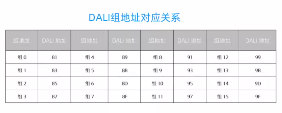
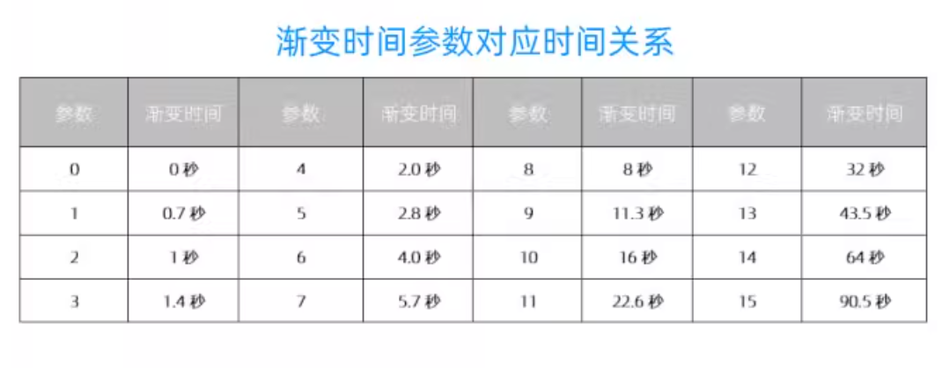
Gradient Time Correspondence
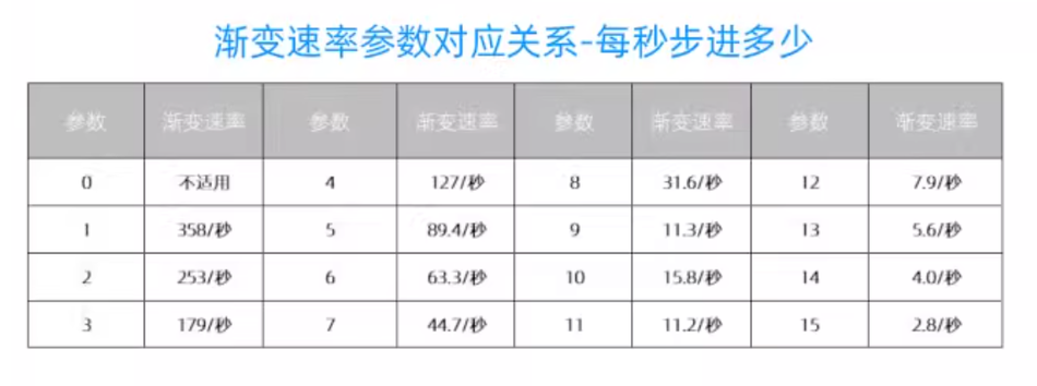
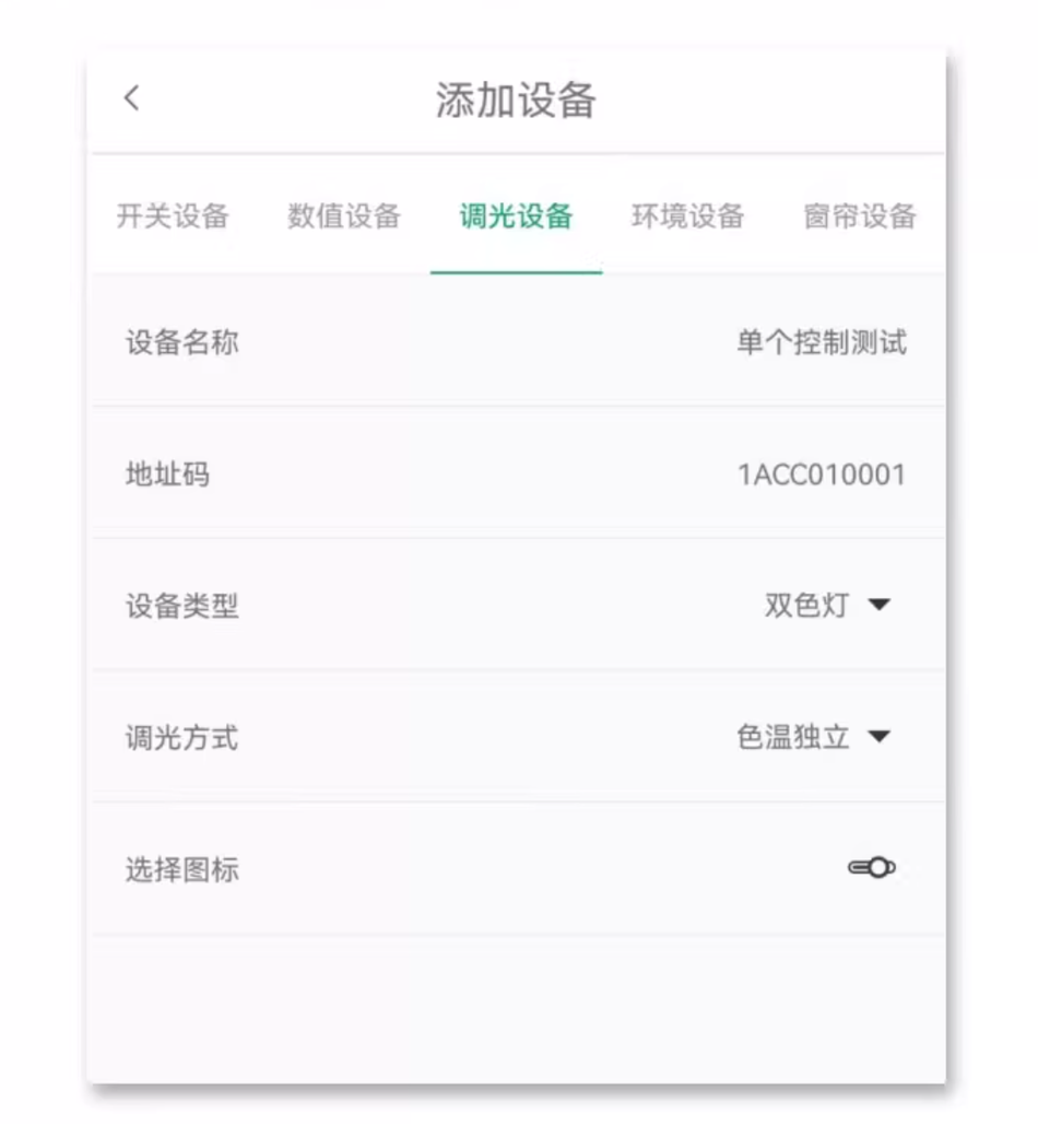
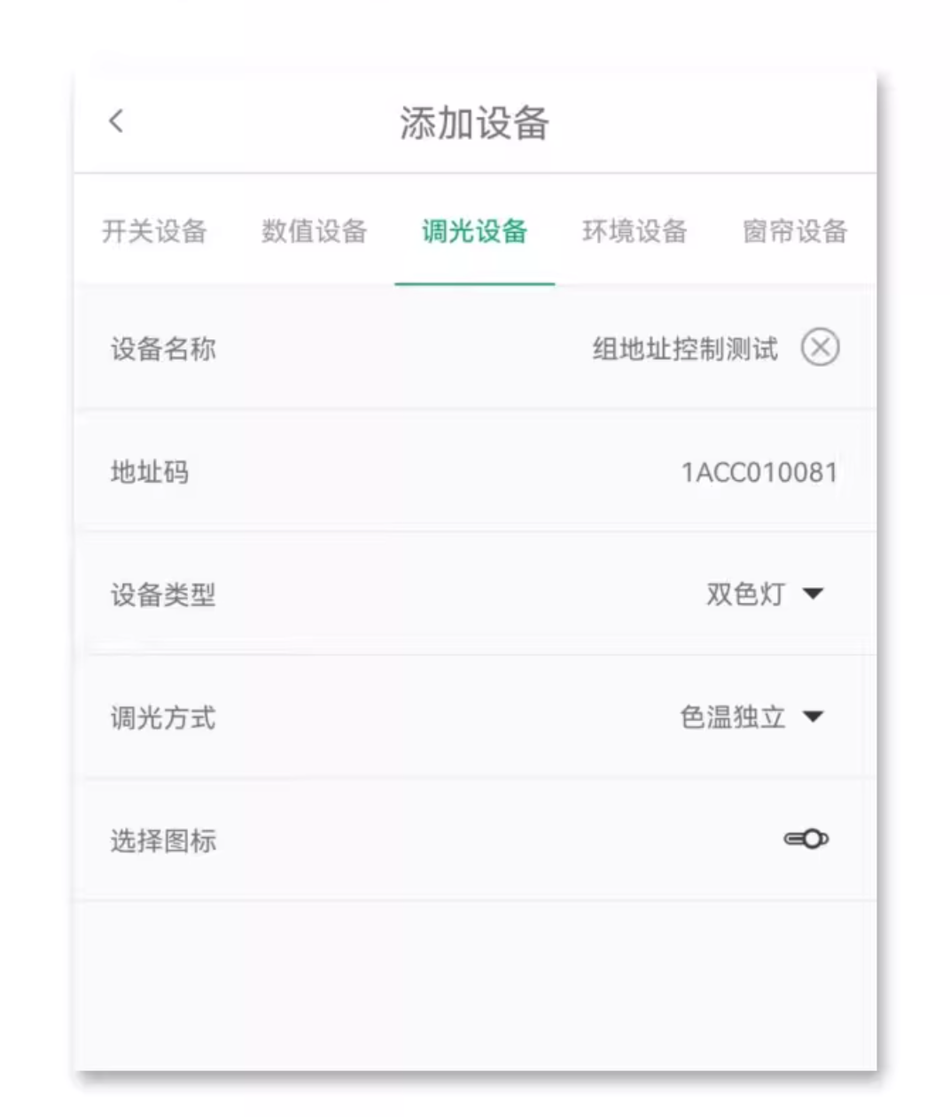
APP Add ControlIndependentAddress
The above screenshot is for a DALI device with gateway address 01
APP Add ControlGroupAddress
The following screenshot takes controlling the lighting ofGroup 1as an example
V. Key Parameter Description
- Color Temperature Calculation Formula:
( text {Tc}=2700_text {K}+29 times text {Value})
- Example:
Value=0x49(73) → (2700+29 times 73 approximate 6500 text {K})
- DALI Dimming Curve:
- Brightness Value
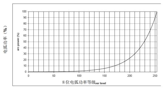
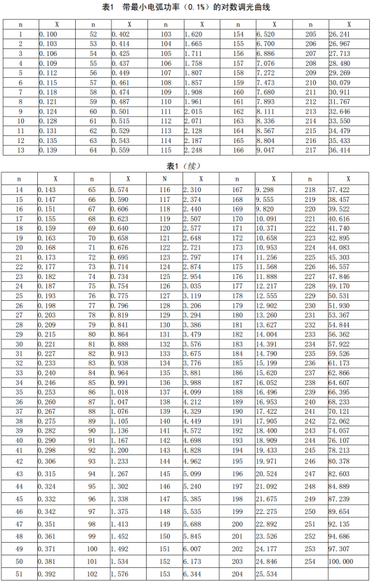
0x00~0xFECorresponding toDALI Pair Dimming Level(0.1%~100%), see Appendix Table 1 of the protocol for details.
- Gradient Time:
- The default gradient time for UP/DOWN instructions is about
200ms, but the actual step size is affected by DALI driving parameters.
VI. Precautions
- The broadcast address (
0xFF) can simultaneously control all DALI devices. - The instruction interval needs to be≥ 100ms, otherwise it may cause communication failure.
- The color temperature function requires DALI driver supportDTS protocol, otherwise the status will return
0x00.
. 7. Software usage instructions
1 , PC Software installation
Download the latest upper computer software, DALI Controller software, and the latest version of DALI Controller from our official website download page
Supports Windows 7, Windows 10, and Windows 11 systems, and Microsoft needs to be installed during installation NET Framework 4.6.1 plugin (if not installed on the computer).
2 , Device Connection
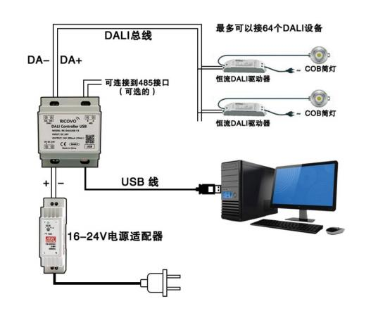
Connect the DALI host to the computer via a USB cable and connect a 24V power adapter to the input terminal of the DALI host. Open the DALIController software, as shown below.
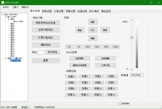
DALIController supports USB hot plugging and automatically connects when clicked. If the connection is successful, the status bar in the bottom left corner of the main page will display "DALI Host: Connected"; If the connection fails, it will display "DALI host: not connected", and it is necessary to check whether the USB cable has been connected properly.
3 , DALI Address Search, Allocation, Deletion, and Modification
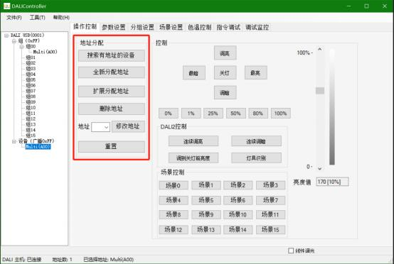
Search, allocate, delete, and modify addresses in the "Address Allocation" section of the "Operation Control" main page:
(1) Search for devices with addresses: Search for devices and display devices with assigned addresses without changing their original addresses. Suitable for searching the device list every time the DALI Controller software is reopened.
(2) New Address Allocation: Delete the addresses of all DALI power supplies on the DALI bus and randomly reassign new addresses to all DALI power supplies. This method is suitable for the first address allocation after installing the lamp.
(3) Extended Allocation Address: To extend the allocation address, first search for DALI power supplies that have already been allocated addresses and display a list, keeping the original address unchanged, and then reassign new addresses to DALI power supplies that do not have addresses; If multiple DALI power supply addresses are duplicated, the DALI power supply with duplicate addresses will be automatically reassigned. Suitable for DALI bus expansion installation and use of DALI power supply.
(4) Delete Address: Select the short address in the device list and click the "Delete addresses" button to delete the device's address.
(5) Modify Address: Select a short address from the device list and enter a short address from 0-63 in the Address input box. Click "Chang" to modify the address of the selected device.
(6) Reset: Reset the DALI power parameters to the default state, but do not delete the short address.
4 , The device list
is divided into two parts: Group and Device. When selecting "DALI USB (0001)", "Group (0xFF)", or "Device (Broadcast 0xff)", it indicates broadcast control. When selecting groups 00 to 15 in the group column, it indicates group control. When A00-A63 in the device column is selected, it indicates single address control.
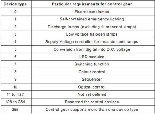
Device Type Definition (see Appendix A for details):
Device Type DT6 displays "LED (Axx)".
Device type DT8 displays "Color (Axx)".
Simultaneously supports multiple device protocols such as DT6&DT8, corresponding to "Multi (Axx)". If the device type is unknown, it will display "Unknown (Axx)". When the address is duplicated, it displays "Error (Axx)".
If the device type is unknown, it will display "Unknown (Axx)".
Display 'Error (Axx)' when the address is duplicated.
5 , “Operation Control”Page Operation Instructions
The "Operation Control" page allows for on/off, brightness adjustment, scene activation, and other operations.
"Darkest": Enable minimum value.
"Brightest": Enable maximum value.
"Turn off lights": Turn off.
"Brightening": Up, brighten for 200ms, with the step determined by the fade rate.
"Dimming": Downward, dimming for 200ms, step determined by the fade rate.
0%, 1%, 25%, 50%, 80%, and 100% are brightness values, with direct power level output. If the Fade Time
parameter is set to a non-zero value, it will have gradient output.
Dimming slider, direct power level output, 0% -100%, with gradient output if the Fade Time parameter is set to a non-zero value.
Scene 0-Scene 15: Scene call, if the Fade Time parameter is set to a non-zero value, it will have a gradient output.
Linear corresponds to a device with a linear dimming curve. If the dimming curve of the DALI power supply is set to 1 (linear dimming curve), selecting it can convert the sliding bar dimming percentage value to a linear percentage value. If not, it will be a logarithmic dimming curve percentage value. At the same time, 0%, 5%, 25%, 50%, 80%, and 100% will also be converted accordingly.
DALI2 control: "Continuous dimming" (a function added to the protocol after DALI2.1) means gradually changing to the maximum power level at a fade rate;
"Continuous Dimming" (a feature added to protocols after DALI2.1) means gradually changing to the minimum power level at a fade rate; Adjusting the brightness before turning off the lights "(a function added to protocols after DALI2.0) refers to calling the software to adjust the brightness before turning off the lights;
"Lamp Recognition" (a function added to protocols after DALI 2.0) indicates a flashing light for 10 seconds, used to find the corresponding light for the address.
6 , “Parameter Settings”Parameter Page Operation Instructions
The parameter table includes all parameters of the standard DALI protocol, which are consistent with the parameter names of the standard protocol, as shown in the following figure.
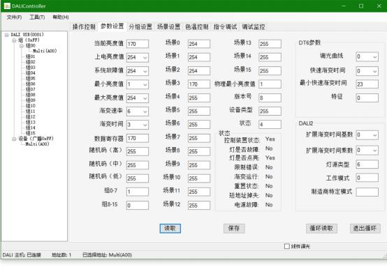
"Power on brightness value": The brightness value when the DALI power supply is turned on (note: if set to 255, the brightness when powered on is the brightness before the last power failure).
"System Fault Value": The brightness value that is turned on when a bus fault is detected in the DALI power supply (note: if set to 255, it will not change).
"Minimum Brightness Value": The DALI power supply can be adjusted to the minimum brightness value.
"Maximum Brightness Value": The maximum brightness value that the DALI power supply can adjust to.
"Gradient Rate": The speed at which brightness is adjusted up and down, divided into 16 levels, as detailed in Appendix D below;
"Gradient Time": The gradient time during direct arc power and scene changes, divided into 16 levels, as detailed in Appendix D.
"Dimming Curve": 0 represents logarithmic dimming curve (see Appendix B), 1 represents linear dimming curve. When the dimming curve changes, the physical minimum power level will switch accordingly, but it is necessary to manually set the MinLevel to the corresponding physical minimum power level and save it to the DALI power supply.
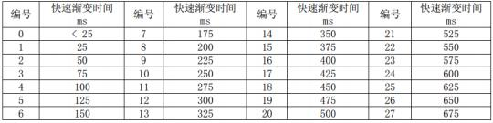
"Fast fade time": When Fade Time is set to 0, the Fast fade time parameter is valid, 0-675ms, and the fade speed is within level 1 of Fade time, as detailed in Appendix E.
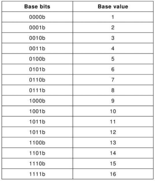
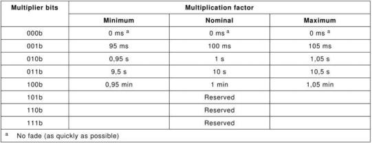
DALI2: "Extended fade time base" and "Extended fade time multiplier" are parameters added to the protocol after DALI2 for extended fade time. When both fade time and fast fade time are 0, the extended fade time will be enabled, ranging from 0-16 minutes. Extended Gradient Time=Extended Gradient Time Base x Extended Gradient Time Multiplier. The level of the extended gradient time base is 0-15, corresponding to a Value value of 1-16; The range of the extended gradient time multiplier is 0-4, corresponding to 0ms, 100ms, 1s, 10s, and 1min. See Appendix F and Appendix G.
Operation Steps:
Please select the address to be operated on on the left
"Read": Read the saved parameter table in the DALI power supply;
"Save": Save the above parameter table to the DALI power supply (note: the software does not save parameters, all parameters are saved in the DALI power supply and will not be lost in case of power failure).
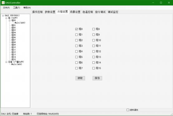
7 , “Group Settings”Group Page Operation Instructions
Group Settings allows you to set and delete the selected settings from their respective groups. The standard DALI has 16 groups, and one device can belong to multiple groups within the 16 groups. Checking the box in the above figure indicates belonging to that group, while not indicating deletion of that group Only devices belonging to this group will affect group control commands
Operation Steps:
Please select the address to be operated on the left.
Read: Read the saved group number from the DALI power supply.
Save ": Save the group number above to the DALI power supply (note: the software does not save parameters, all parameters are saved in the DALI power supply and will not be lost in case of power failure).
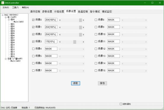
8 , “Scenario Setting”Scenario page operation instructions
The scene displayed on the interface is consistent with the 16 scenes defined in the standard DALI protocol.
MASK ->indicates blocking the scene, meaning that when the scene is turned on, the device is not affected;
0%~100% ->represents brightness value When the scene is turned on, the brightness value will be automatically called up;
Operation steps:
Please select the address to be operated on the left.
Read: Read the saved scene values from the DALI power supply.
Save ": Save the scene values above to the DALI power supply (note: the software does not save parameters, all parameters are saved in the DALI power supply and will not be lost in case of power failure).
Linear corresponds to a device with a linear dimming curve. If the DALI power supply has a linear dimming curve, selecting it can convert the sliding bar dimming percentage value to a linear percentage value, while selecting it will convert it to a logarithmic dimming curve percentage value.
9 , “Color Temperature Control”Color temperature page operation instructions
The color temperature control page is used for DALI DT8 color temperature control and settings, including the Color Temperature Control page, Color Scene page, and Color Temperature Limit Setting page.
(1) Color temperature control page
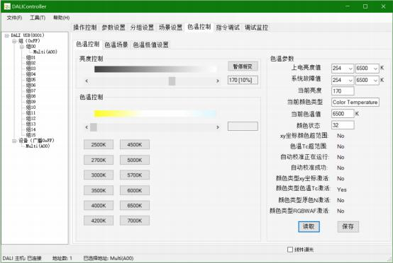
Brightness Control: The slider is used for adjusting brightness.
Color temperature control: The slider is used for color temperature control, with a color temperature range of 2500K-7000K.
2500K, 2700K, 3000K, 3500K, 4000K, 4200K, 4500K, 5000K, 5700K, 6000K, 6500K Call the preset color temperature of 7000K.
Power on brightness value ": the setting and reading of power on brightness and power on color temperature.
System fault value: Setting and reading of system fault brightness and color temperature.
Read the current brightness value, current color type, current color temperature value, and color status.
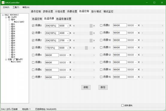
(2) Color temperature scene page
The scene displayed on the interface is consistent with the 16 scenes defined in the standard DALIDT8 protocol, and color types and values have been added. This version only supports the setting of color temperature color types and color temperature values.
MASK ->indicates blocking the scene, meaning that when the scene is turned on, the device is not affected;
0%~100% ->represents the brightness value, which means that when the scene is turned on, the brightness value will be automatically called up;
2500K-7000K represents the color temperature value. When this scene is turned on, the color temperature value will be called. This version fixes the color type as color temperature.
Operation steps:
Please select the address to be operated on the left.
Read: Read the saved scene values from the DALI power supply.
Save ": Save the scene values above to the DALI power supply (note: the software does not save parameters, all parameters are saved in the DALI power supply and will not be lost in case of power failure).
Linear corresponds to a device with a linear dimming curve. If the DALI power supply has a linear dimming curve, selecting it can convert the sliding bar dimming percentage value to a linear percentage value, while selecting it will convert it to a logarithmic dimming curve percentage value.
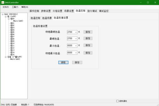
(3) Color temperature extreme value setting page
This page is used for reading and setting the warmest color temperature, coldest color temperature, physical warmest color temperature, and physical coldest color temperature.
Physical Warmest Color Temperature ": The physical warmest color temperature should be less than or equal to the warmest color temperature, coldest color temperature, and physical coldest color temperature. The reset command does not affect this parameter.
Warmest color temperature ": The warmest color temperature should be greater than or equal to the physical warmest color temperature, and less than or equal to the coldest color temperature and the physical coldest color temperature. When resetting the command, the warmest color temperature is saved as the physical warmest color temperature.
Coldest color temperature ": The coldest color temperature must be greater than or equal to the physical warmest color temperature and the warmest color temperature, and less than or equal to the physical coldest color temperature. When resetting the command, the coldest color temperature is saved as the physical coldest color temperature.
Physical Coldest Color Temperature ": The physical coldest color temperature must be greater than or equal to the physical warmest color temperature, warmest color temperature, and coldest color temperature. The reset command does not affect this parameter.
Operation steps:
Read: Read parameters.
Save ": Save the above values to the DALI power supply (note: the software does not save parameters, all parameters are saved in the DALI power supply and will not be lost in case of power failure).
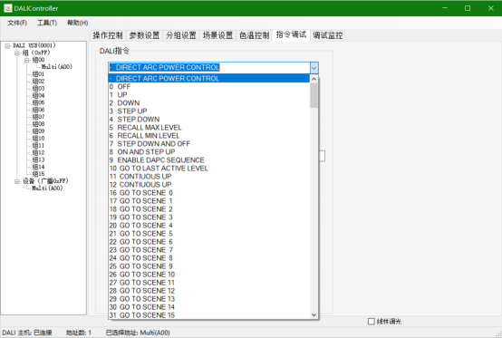
10 , “Instruction debugging”Instructions for operating the instruction sending page
This page is used for sending and replying to a single DALI command, supporting the sending of DALI2 commands.
V. DALI Host Wiring Diagram
VI. Appendix
Appendix A: Equipment Type Correspondence Table
Appendix B: Logarithmic Dimming Curve
Appendix C: Parameter Table
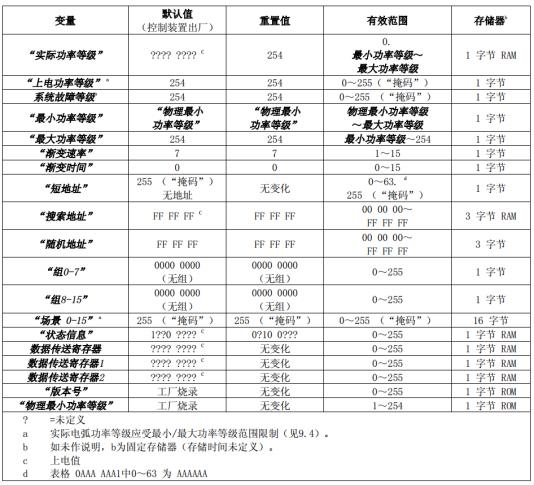
Appendix D:Gradient Rate and Gradient Schedule
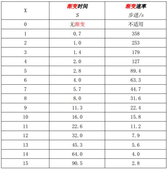
Appendix E: Fast Gradient Schedule
Appendix F: Extended Fade Time - Base Value Table
Appendix G: Extended Fade Time- Multiuplier Table


Leave a Reply