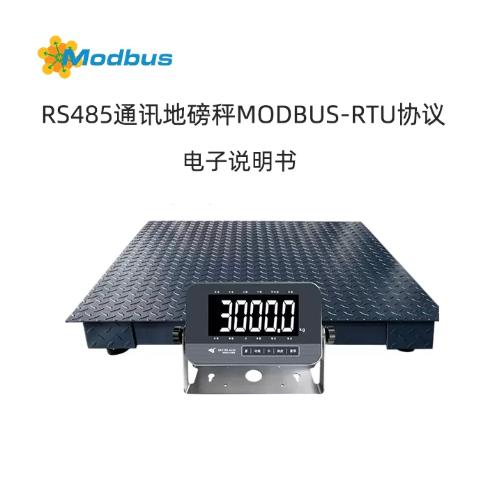
Chapter 1 Technical Parameters
- Display 【 noLoAd 】, there is no object on the scale platform. Wait for the stability indicator ▼ to appear, press the 【 # 】 key to complete the zero calibration and enter the range calibration state.
- WiFi communication protocol (this parameter is only available in STA working mode), x=1: continuous transmission (refer to other settings pages in WiFi related instructions for relevant configuration); X=2: Connect to Yaohua Cloud (there are related supporting desktop apps and Android mobile apps available for download on Yaohua's official website). When P11 is set to 2, press the # key to configure the WiFi card parameters. If there is a WiFi card and the settings are normal, the instrument panel will display [t *], where * is any number. The configuration only needs to be completed once and does not need to be repeated. If error is displayed, the instrument panel will power off and try again. If error is still displayed, it is considered that the WiFi configuration is abnormal; How to set up the instrument to connect to the on-site WiFi? Please refer to the STA settings page in the WiFi related instructions; When P11 is set to 2, the peak light flashes to indicate that the server is connected; (P2 cannot be set to 3), after connecting to the server, pressing the instrument * key to accumulate data will upload the weighing data to the Yaohua Cloud platform, which needs to be reset to zero before it can be accumulated again; When P11 is set to 2, the instrument buzzer will sound once after a few seconds to indicate that the instrument has not been registered. Please use the mobile or computer app downloaded from the official website to activate the instrument (please consult after-sales for mobile and computer app accounts)
- XOR check high 4 bits
- variable
- Input signal range: -19 ~ 19mV
- Sensor excitation voltage Uexc: DC 5V, 120mA
- Error allocation coefficient: Pi=0.5
- The minimum input signal for each calibration division value: 1μV/e
- Sensor connection method: Six wire system, Can be connected 4 One 350Ω The sensor, The minimum impedance of the sensor is about 90Ω, Most approximately 350Ω, The material is copper, Length 200m, Cross-sectional area 0.5mm²
- Display: 6 Position LED, Word height 50.8mm, 12 A status indicator, Division value 1/2/5/10/20/50/100 Optional
- Keyboard: Light touch film button
- Large screen display interface:
- Transmission method: (1)20mA Current loop (Constant current source output) , Transmission distance ≤2000 Rice
- Serial communication interface: RS485: Support multiple custom formats, Support standards MODBUS-RTU Communication protocol; RS232C
- USB Communication function
- Relay output: Three relay outputs, Contact capacity 24V AC/DC, 0.5A
- Baud rate: Optional 1200/2400/4800/9600, Transmission distance RS232: ≤30m
- Power Supply: UAC 220V/50Hz, 14.8V/2.2AH Battery, Rated power 10W
- Operating temperature: 0℃~40℃, Storage and transportation temperature: -25℃~55℃, Relative humidity ≤85%RH, Preheating time 15min
- Specification composition: XK3190-A33E, Product serial number: 33E, Product classification: A Series platform scale instruments, Design serial number: 90, Applicable types of scales: 1 Non automatic weighing apparatus
- External dimensions: 223×210×158 (mm) , dead weight 0.8kg
Chapter 2 Installation and Connection
One, Schematic diagram of instrument display and keyboard functions
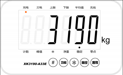
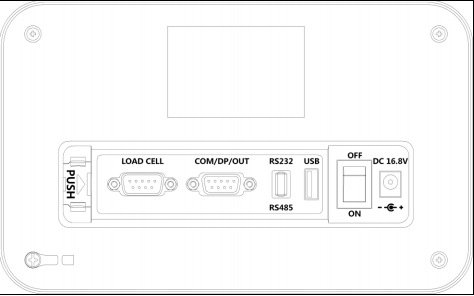
Two, Keyboard function
- 【#】: Press and hold this button during the power on self-test to enter calibration mode.
- [Function]: When in the weighing state, Pressing this key is greater than 3 Seconds, Press this key to enter user settings mode.
- 【*】: When in the weighing state, Press this key to accumulate the current weight.
- [Skin removal]: When in the weighing state, Press this key to remove tare weight.
- Set to zero: When in the weighing state, Pressing this button will display the weight as zero.
Three, Connection between sensors and instruments
- The connection of sensors is adopted 9 Core plug socket, The meanings of each pin are detailed in the diagram 2-3.
- Use six core shielded cables, Ensure good metrological performance of the instrument.
Note The connection between sensors and instruments must be reliable : The shielding wire of the sensor must be reliably grounded, Connecting wires are not allowed to be plugged or unplugged while the instrument is powered on. Prevent static electricity from damaging instruments or sensors, Sensors and instruments are both electrostatic sensitive devices. Effective anti-static measures must be taken during use, It is strictly prohibited to perform welding or other high-voltage operations on the weighing platform, During thunderstorm season; Reliable lightning protection measures must be implemented, Prevent damage to sensors and instruments caused by lightning strikes, Ensure the personal safety of operators and the safe operation of weighing equipment and related devices, Four.
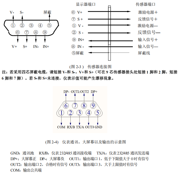
The connection between the large screen and the instrument panel, The large screen signal is
Constant current loop signal 20mA Serial output in binary code, The baud rate is, Please refer to the diagram for the connection method between the instrument and the large screen 600. The connection between the output leads of the instrument large screen and the large screen display must be accurate and error free 2-4. If the connection is incorrect, Damaging the output port of the instrument or damaging the input port of the large screen display, It may even cause serious damage to instruments and large screen displays, Require the use of matching dedicated connecting wires, Five.
Connection between serial communication interface and instrument, The connection between the communication interface output lead and the computer must be accurate and error free
If the connection is incorrect, Damaged instrument output ports or computer communication input ports, Even severely damaging instruments, computers, and corresponding external devices, Necessary computer technology and programming skills are required for computer communication. Professional technical personnel must participate or provide guidance, Non professionals, please do not connect randomly. The instrument has.
XK3190-A33E Serial communication interface RS232/RS485 Can be connected to computers, Touch screen communication, PLC, Please refer to the diagram for the instrument connection method. It can be selected through the communication terminal behind the instrument panel 2-4. (It can be selected through the communication terminal behind the instrument panel RS232 Or RS485, Please refer to the appendix for detailed format - Serial communication)
Communication interface adopted RS232C, All data are ASCII Code. The data format is: 1 A starting position, 8 Data bits, 1 A stop position, No verification. Communication methods are divided into the following categories::
Method one, P6=2: Continuous transmission, The transmitted data is for weighing (Gross weight, Net weight or tare weight, From P5 Parameter determination) , The gross weight format is:: ww000.000kg Or ww000.000lb; The net weight format is:: wn000.000kg Or wn000.000lb; The tare weight format is: wt000.000kg Or wt000.000lb.
Method 2, P6=3: Continuously send after stabilization, Sending content is the same as method one.
Method three, P6=7: Continuous transmission (A7 Format) , Data format: = <Weight data (Including decimal point) >: Six digit signed weight data including decimal point, ASCII Code. The weight data are all at the lowest position first, The high and sign bits are at the end. Send negative sign bits as “-”, When positive, the sign bit is sent as 0. For example: The current weight displayed on the instrument is 500.00kg, The serial output data is:: = 00.0050.
Six, USB Connection between interfaces and instruments
The communication methods and protocols are as follows:: (A1+,C8 Continuous communication mode) give an example: (-100.0)
| name | Byte position | meaning | ASCII Code | 16 Base system |
|---|---|---|---|---|
| Starting byte | 1 | Starting byte | 02 | 02 |
| Symbol position | 2 | Symbol position | 2D | 2D |
| First place in weight data | 3 | First place in weight data | 30 | 30 |
| Second place in weight data | 4 | Second place in weight data | 30 | 30 |
| Third place in weight data | 5 | Third place in weight data | 31 | 31 |
| Fourth place in weight data | 6 | Fourth place in weight data | 30 | 30 |
| Fifth place in weight data | 7 | Fifth place in weight data | 30 | 30 |
| Sixth place in weight data | 8 | Sixth place in weight data | 30 | 30 |
| Number of decimal places | 9 | Number of decimal places | 31 | 31 |
| XOR check high 4 Position | 10 | XOR check high 4 Position | 31 | 31 |
| XOR check low 4 Position | 11 | XOR check low 4 Position | 45 | 45 |
| End byte | 12 | End byte | 03 | 03 |
XOR verification: XOR all data starting from the second byte, The 10 Byte is the top four bits ASCII Code, The 11 Byte is the lower four bits ASCII Code. If the data is a positive number, The second byte is (2B[HEX])
Note:: USB Connecting to the computer requires installing relevant drivers, Please download the driver and installation instructions from the official website of Yaohua.
Chapter 3 Instrument Calibration Instructions
One, General calibration method
During the startup initialization process, long press the 【 # 】 key until the stroke self-test is complete, The instrument enters the calibration state, Display 【d X】. Follow the steps below step by step:
- Set the division value : Display 【d X】, Press the 【 Skin Removal 】 key to select 1, 2, 5, 10, 20, 50, Press the 【 # 】 key to confirm, Automatically enter the next parameter setting. Press the 'Peel' button to automatically display in a step-by-step loop. For example, when displaying [d 5], Press the [#] key, The division value is set to 5, And automatically enter the decimal point setting state.
- Decimal point setting : Display 【P X】, Press the 【 Skin Removal 】 key to select 0, 1, 2, 3 Decimal places, Press the 【 # 】 key to confirm, Automatically enter the next parameter setting. Press the 'Peel' button to automatically display in a step-by-step loop. For example, in displaying【P 0.000】Time, Press the [#] key, The decimal point is set to 0.000, And automatically enter the maximum scale setting state.
- Maximum scale capacity setting : Display 【FULL 】, Press the 【 Skin Removal 】 key to enter the numerical input state. Display 【0 0 0 0 0 0】, Press the 【 Peel 】 button, Symbol▼Move to the right one by one to select the number input position, Press the 'Zero' button to automatically step up to one for the corresponding position, Until the required number appears, Press the 'Remove Skin' button icon again▼Move to the right one by one to select the number input position, Press the 'Zero' button to automatically step up to one for the corresponding position, Until the maximum weighing value appears, Press the 【 # 】 key to confirm, Automatically enter the zero calibration state. For example, display [0 2 5 0 0 0] and press the [#] key to confirm, And automatically enter the zero calibration state.
- Zero point calibration : Display: There is no object on the weighing platform. Wait for the stability indicator to appear. Press the [#] keynoLoAd】, Zero calibration completed, Enter the range calibration state▼Full scale calibration, Display 【, Place weights on the weighing platform, Press the 【 Skin Removal 】 key to enter the input state.
- Display 【 : Press the 【 Peel 】 buttonAdLoAd】, Symbol, Move to the right one by one to select the number input position. Press the 'Zero' button to automatically step up to one for the corresponding position0 0 0 0 0 0 】, Until the required number appears, Press the 'Remove Skin' button icon again▼Move to the right one by one to select the number input position, Press the 'Zero' button to automatically step up to one for the corresponding position, Until the displayed number matches the weight of the weight, When the stability indicator is present▼When it appears, Press the 【 # 】 key to confirm, End range calibration status, Display 【▼lightly touch the calibration switch button on the back of the instrument, the instrument will save parameters, return to the weighing state. Chapter 4 Operating Instructions End】.
- 1. Power on and automatic zeroing, after power on, the instrument performs stroke self-test.
enter the weighing state after initialization
when turned on, Power on and automatic zeroing upon startup
- After connecting the power supply, Instrument for “000000~999999” Stroke self check, After initialization is completed, enter the weighing state.
- When booting up, If the weight of the weighing platform deviates from zero, But still within the set zero range, The instrument will automatically reset to zero; If it is outside the set zero range, The instrument will sound an alarm “Err 3”, Prompt exceeding the zero setting range, At this point, it is necessary to remove heavy objects from the weighing platform, adjust the zero position of the weighing body, or recalibrate, set up.
Two, Manually reset to zero ( Semi automatic zeroing )
- In weighing state, If there is a deviation when the scale is empty, Press the 'Zero' button, Can reset the instrument to zero.
- When the displayed value deviates from zero but is still within the zero setting range, Press the 'Zero' button to activate. Otherwise, pressing the 'zero' button will not work. (At this point, it is necessary to recalibrate or set the zero setting parameter)
- Only when the stability indicator is on, Zero setting operation can be performed.
Three, Skin removal function
In the weighing display state, Display weight as positive, And when stable, Press the 'Remove Skin' button to deduct the current weight as tare weight, At this time, the instrument displays the net weight as 0, The net weight symbol is on.
Four, Peak retention, Average value, Counting function
Through functional settings P2 Select enablement, After selection, The selection function can be started or stopped by pressing the 【 # 】 key. Like:
- P2 choice 2, The average value light is on, At this time, the instrument automatically judges, When relatively stable, The instrument starts calculating and displaying the average value, And display the average value after flashing, Cancel displaying the average value after the current weight returns to zero, You can continue to weigh the next average value;
- P2 choice 3, Peak light on, The instrument is in automatic peak maintenance working state, Can maintain maximum weighing data, After the weight returns to zero, Release data retention;
- P2 choice 4, Counting scale mode, Press the 【 # 】 key, Press 【 # 】 to display the weighing status “Count”, Press 【 # 】 to display “C00000”; After placing the sample for sampling, Press the 'Set to Zero' and 'Remove Skin' keys to enter their quantity, Press [#] to confirm; After the instrument automatically calculates the unit weight, Display “Cn in” The counting indicator light is on, Enter the counting state; If the input sample quantity is 0, Instrument prompt “Err 4”, And call the unit weight stored last time as the calculation benchmark; In counting state, Press 【 # 】 to display “Cn End”, The instrument exits the counting state.
Five, Cumulative function
- Manual accumulation: Under normal weighing conditions, When the measurement data is greater than or equal to 20 Scale division and stable data, Press the 【】 key, Instrument execution “Manual accumulation of measurement values” Function. At this moment, The instrument will first display the accumulated total data (Divided into two steps) : [total =] (The content displayed below is the accumulated total amount data) Display approximately 1 Display accumulated data in seconds [*], Then display the total accumulated count (Divided into two steps) : [n =] (The number displayed below is the number of times) Display approximately 1 After seconds, the accumulated count will be displayed **], Then the cumulative indicator light 【】 lights up.
- Press the 【】 key when the scale is empty to display the cumulative number of times [n ], Press the 【】 key again to display the cumulative weight [A*], Press the 【】 key again to return to weighing.
- Short press the [Function] key in cumulative mode to clear the current cumulative value.
Six, Pre set tare weight and upper and lower limit alarms
Under normal weighing conditions, Long press the 【 # 】 key. The steps are as follows::
| Steps | Operation | Display | Explanation |
|---|---|---|---|
| 1 | [*******] | Weighing display status | |
| 2 | Long press the 【 # 】 key | [P00000] | Prompt the user to input the preset tare weight value. The preset tare weight can only be set to a maximum of 5 Bit tare weight. |
| 3 | Enter the preset tare weight value, Press the [#] key to confirm | [ 6000 ] | For example “6000” |
| 4 | Enter the upper limit alarm value, Press the [#] key to confirm | [H 00000] | For example “3000” |
| 5 | Enter the lower limit alarm value, Press the [#] key to confirm | [L 00000] | For example “0” |
| 6 | [*******] | Return to weighing status, Display the net measurement result after skin removal |
Seven, User function settings
In the weighing state, Press the [Function] key greater than 5 Seconds, Enter user settings mode, The user settings mode includes: P1~P12 Twelve parameter settings, Press the 'Remove Skin' button to change the value, Press the 【 * 】 key to select the next parameter. The parameter description is as follows::
- P1 x : kg Lb transformation, x=1: kg Display; x=2: Lb Display
- P2 x : Function selection, x=1: No other functions; x=2: Activate the animal scale function; x=3: Enable peak hold function; x=4: Enable the counting function
- P3 x : Baud rate setting, x=1: 9600; x=2: 4800; x=3: 2400; x=4: 1200
- P4 xxx : 485 Communication address setting, Command response method x=1-26; Modbus Communication method x=1-127
- P5 x : RS232 Output net weight, Gross weight, Tare weight selection, x=1: Output net weight; x=2: Output gross weight; x=3: Output tare weight
- P6 x : Communication method selection (Among them 2 - 9 For 232 Sending mode, 10 - 13 For 485 Command mode, Figure 2 - 2 232/485 The communication switch needs to be switched accordingly, Please refer to the appendix for specific protocol instructions) , x=1: Not sending; x=2: Continuous transmission; x=3: Continuous transmission when stable; x=4: Continuous transmission AD Code; x=5: A1+,C8 Continuous communication mode; x=6: Zhimei Communication Protocol; x=7: A7 Communication protocol; x=8: External receipt printer; x=9: External label printer; x=10: Yaohua command mode; x=11: Zhimei command method; x=12: Changlu Command Method; x=13: MODBUS-RTU Communication protocol
- P7 x : Zero point tracking range, x=1: 1.0e; x=2: 2.0e; x=3: 3.0e; x=4: 4.0e; x=5: 5.0e; x=6: Do not track
- P8 x : Zero key range, x=1: 2%FS; x=2: 4%FS; x=3: 10%FS; x=4: 20%FS; x=5: 100%FS; x=6: Prohibit manual zeroing
- P9 x : Zero point range during startup, x=1: 2%FS; x=2: 4%FS; x=3: 10%FS; x=4: 20%FS; x=5: 100%FS; x=6: Prohibit starting up and resetting to zero
- P10 x : Digital filtering strength, x=1: Weak; x=2: In the middle; x=3: Strong; x=4: Strong
- P11 x : wifi Communication protocol (STA This parameter is only available in working mode) , x=1: Continuous transmission (see wifi Configure other settings pages in the relevant instructions) ; x=2: Connect to Yaohua Cloud (There are related supporting computer terminals available APP And Android phones APP, It can be downloaded from the official website of Yaohua) . When P11 Set as 2 Time, Press # Keys can be configured wifi Board parameters, If any wifi If the board is set normally, the instrument will display [t * ], * For any number, Configuration only needs to be completed once, No need for repeated configuration, As shown error Power off the instrument and try again, If still displayed error, It is believed that wifi Configuration exception; How to set up the instrument to connect to the site wifi Please review wifi In the relevant explanation STA Set up the page; When P11 Set as 2 Time, Flashing peak light indicates connection to the server; (P2 Cannot be set as 3) , After connecting to the server, According to the instrument * When accumulating data, the weighing data will be uploaded to the Yaohua Cloud platform, Must return to zero before accumulating again; When P11 Set as 2 Time, The instrument buzzer will sound once after a few seconds to indicate that the instrument has not been registered, Please use the mobile phone or computer downloaded from the official website app Activate the instrument ( Mobile phones and computers APP Please consult the after-sales service for the account )
- P12 x : Stable amplitude, x=1: Low; x=2: In the middle; x=3: High
- C high 5 Instrument number : Process consistency needs to be checked;
- C Low 5 Instrument number : Process consistency needs to be checked; (The combination of high and low instrument numbers forms the complete instrument number)
Eight, wifi Related explanations (Optional selection)
A33E wifi By default, it works when leaving the factory APSTA Dual mode, Can only be configured online wifi Account and password, HF-LP230 Network default settings table:
| Parameters | Default settings |
|---|---|
| SSID | HF-LPT230 |
| user name | admin |
| password | admin |
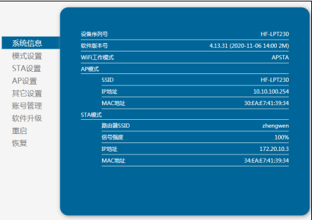
- System information page : On this page, Users can obtain important status information of the current device, include: Equipment serial number, Firmware version, Wireless networking information and related parameter settings. And it can be read STA Wireless signal strength indication in mode.
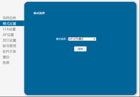
- Mode selection page : HF-LP230 The module can serve as a wireless access point (AP pattern ) Convenient for users to configure devices, It can also serve as a wireless information terminal (STA pattern ) Connect to remote servers through wireless routers. The mode selection is AP+STA Do not move the mode.
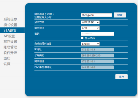
- STA Set up the page : On this page, Users can click [ Search results ] The button automatically searches for nearby wireless access points, And connect to it by setting network parameters. The encryption and other information provided here must be consistent with the corresponding wireless access point in order to connect correctly.
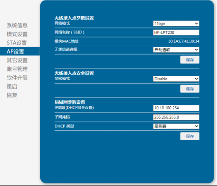
4.AP Set up the page : This page settings AP Wireless and network parameters. Most systems support it DHCP Automatic acquisition IP, We suggest that you set LAN parameters DHCP The type is “The server”, This page can change the hotspot name.
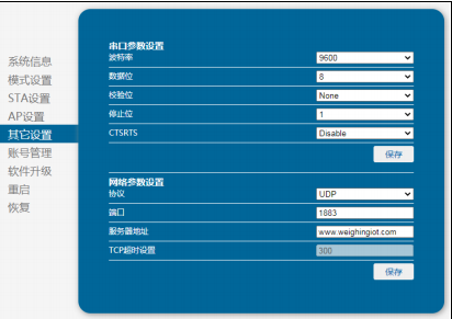
5.Other settings pages : Wireless modules generally work in “Data transmission mode”. In this mode, The devices connected to the wireless module will directly communicate with the remote computer. On this page, Users need to set serial communication parameters and TCP Protocol parameters for communication between layers and remote devices. The default baud rate of the module 9600 Do not change, The network parameters of this interface are as follows: P11 Set as 1 This network parameter can be used when needed, The instrument can be used as a client (The protocol is set to: TCP-CLIENT) , It can also serve as a server (The protocol is set to: TCP-SERVER) , When P11 For 2 Do not modify the network parameters on this interface.
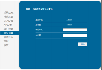
6.Account management page : This page is designed for users to use for device integration Web Server The username and password.
Chapter 5 Maintenance and Precautions
- To ensure clear instrument display and service life, This instrument should not be used in direct sunlight, The placement location should be relatively flat.
- Not suitable for use in places with severe dust and vibration, Avoid using in damp environments.
- Sensors and instruments must be reliably connected, The system should have good grounding, Stay away from strong electric fields, Strong magnetic field, Sensors and instruments should be kept away from highly corrosive objects, Stay away from flammable and explosive materials.
- Before plugging and unplugging the sensor connection wire, The instrument power must be cut off first (Shut down) !
- Before plugging and unplugging the large screen connection cable, The instrument and large screen power must be cut off first!
- Before plugging and unplugging communication cables, The instrument and upper computer power must be cut off first!
- It is strictly prohibited to use strong solvents (Like: Benzene, Nitro based oil) Clean the casing.
- Do not inject liquids or other conductive particles into the instrument, To prevent instrument damage and electric shock.
- Before plugging and unplugging the instrument and connecting it to external devices, The power supply of the instrument and corresponding equipment must be cut off first!
Warning : Do not use in environments with flammable gases or vapors; Not allowed to be used in pressure vessel canning systems. In areas where lightning frequently occurs, Reliable lightning arresters must be installed, To ensure the personal safety of operators, Prevent lightning strikes from damaging instruments and corresponding equipment. Sensors and instruments are both electrostatic sensitive devices, Effective anti-static measures must be taken during use, It is strictly prohibited to perform welding or other high-voltage operations on the weighing platform; During thunderstorm season, Reliable lightning protection measures must be implemented, Prevent damage to sensors and instruments caused by lightning strikes, Ensure the personal safety of operators and the safe operation of weighing equipment and related devices.
- The company advises customers: Before using our company's instruments, they should be inspected and accepted. Our company is only responsible for the quality of the instruments themselves, The maximum compensation amount is based on the intrinsic value of the faulty instrument 2 Within times, Not responsible for the system issues where the instrument is located.
- The external interface of the instrument must be strictly used according to the methods indicated in the user manual, Do not change the connection without authorization. If this table malfunctions during use, The plug should be unplugged immediately, Send to a professional factory for repair. Non professional manufacturers of weighing instruments should not repair themselves to avoid causing greater damage. This instrument is not allowed to be opened at will, Otherwise, no warranty will be provided.
- Within one year from the date of sale of the instrument, Under normal usage conditions, Non human caused malfunctions are covered by the warranty, Please ask the user to provide the product and warranty card (The number matches) , Send together to designated repair points or suppliers. The production plant implements lifelong maintenance for instruments.
- Instrument charging instructions:
- Just connect the randomly included charger, The charger indicator light is on, Charging the battery, Rechargeable in both on and off states. The green indicator light of the charger indicates that the battery is fully charged.
- The low voltage alarm undervoltage indicator light is on, It is necessary to charge the instrument in a timely manner. The built-in battery of the instrument is a consumable item, Not within the scope of the three guarantees.
Chapter 6 Information Reminder
- Err 1 : When indicating full calibration AD The value is too small. (Please choose a sensor with appropriate weighing capacity)
- Err 2 : Indicates that manual zeroing exceeds the allowable range. (Please check if there are any heavy objects on the weighing platform)
- Err 3 : Indicates that the zero position exceeds the set range during startup. (When starting up, the weight on the weighing platform should be kept at zero)
- Err 4 : Indicate the counting status, When sampling samples, The input sample size is zero. (ERR 4 Display 1 In seconds, Enter the counting working state, At this time, work according to the results of the previous sample sampling, When resampling, the sample size input cannot be zero)
- Err 5 : Indicate the calibration status, When fully calibrated, The input weight is zero. (Please enter the same weight data as the weight on the scale platform)
- Err 6 : Indicate the counting status, When sampling samples, The weight of a single item is less than 0.25e. (Please re-enter the sample size)
- Err7 : Indicating a sensor wiring fault, During calibration loading AD Negative code growth. (Please check if the sensor signal wire is connected incorrectly)
Warning : After assembling this instrument into an electronic scale, There must be markings on the product that comply with relevant national regulations.
Appendix Serial Communication
One, Serial port (RS232)
- P6 Communication mode 4 : Continuous transmission AD Code examples: (AD Value 524212)
| name | The first byte | Second byte | The third byte | The fourth byte | The fifth byte |
|---|---|---|---|---|---|
| 16 Base system | 02 | B4 | FF | 07 | 03 |
- P6 Communication mode 5 : (A1+,C8 Continuous communication mode) give an example: (-100.0)
| name | The first byte | Second byte | The third byte | The fourth byte | The fifth byte | The sixth byte | The seventh byte | The eighth byte | The ninth byte | The tenth festival | The eleventh byte | The twelfth byte |
|---|---|---|---|---|---|---|---|---|---|---|---|---|
| meaning | Starting byte | Symbol position | First place in weight data | Second place in weight data | Third place in weight data | Fourth place in weight data | Fifth place in weight data | Sixth place in weight data | Number of decimal places | XOR check high 4 Position | XOR check low 4 Position | End byte |
| ASCII Code | 02 | 2D | 30 | 30 | 31 | 30 | 30 | 30 | 31 | 31 | 45 | 03 |
XOR verification: XOR all data starting from the second byte, The 10 Byte is the top four bits ASCII Code, The 11 Byte is the lower four bits ASCII Code. If the data is a positive number, The second byte is (2B[HEX])
- P6 Communication mode 6 : (Zhimei Communication Protocol)
Communication mode (Zhimei Communication Protocol)
| Name | Byte 1 | Delimiter | Byte 2 | Delimiter | Byte 3 | Delimiter | Byte 4 - 17 | Byte 18 |
|---|---|---|---|---|---|---|---|---|
| meaning | Status byte 1 | , | Status byte 2 | , | 8 Weight data (Contains symbol decimal point units, ASCII) | Company k Or g | Enter and wrap | |
| 16 Base system | 53 54 Or 55 53 Or 4F 4C | 2C | 47 53 Or 4E 54 | 2C | For example: - 0.1000kg Corresponding ASCII The code is 2D 30 2E 30 30 30 30 6B Or 67 | 0D 0A |
Note:: When the decimal point is 0 Time period 8 A byte is
Two, Serial port (RS232/RS485)
- P6 Communication mode 10 (Yaohua command mode)
explain: The verification byte sent by the instrument is: XH And XL. The verification calculation method is:: Check the byte before division 02 Perform XOR verification on all external data, Obtain data as one byte. XH For high four digit data ASCII Code, XL For the fourth data ASCII. For example, sending from the upper computer 02 41 42 30 33 03 XOR verification is 0x41 And 0x42 Obtained through XOR verification 0x03, XH For the top four positions 0 of The code is ASCII For the lower four positions 0x30, XL of The code is 3 Instructions ASCII meaning 0x33.
| Format | give an example | Sent by the upper computer | handshake |
|---|---|---|---|
| A | Instrument sending | handshake: 02 AD 41 XH XL 03 | 02 41 41 30 30 03 |
| Instrument sending | handshake: 02 AD 41 XH XL 03 | 02 41 41 30 30 03 | |
| B | Sent by the upper computer | Read gross weight: 02 AD 42 XH XL 03 | 02 41 42 30 33 03 |
| Instrument sending | Send gross weight: 02 AD 42 ** ** ** * * XH XL 03 | 02 41 42 2B 30 30 31 2E 30 30 30 30 37 03 | |
| C | Sent by the upper computer | Read net weight: 02 AD 43 XH XL 03 | 02 41 43 30 32 03 |
| Instrument sending | Send net weight: 02 AD 43 ** ** ** * * XH XL 03 | 02 41 43 2B 30 30 30 2E 30 30 30 30 31 03 | |
| D | Sent by the upper computer | Read tare weight: 02 AD 44 XH XL 03 | 02 41 44 30 35 03 |
| Instrument sending | Sending tare weight: 02 AD 44 ** ** ** * * XH XL 03 | 02 41 44 2B 31 2E 30 30 30 30 31 03 | |
| E | Sent by the upper computer | peel: 02 AD 45 XH XL 03 | 02 41 45 30 34 03 |
| Instrument sending | Peel successfully: 02 AD 45 32 34 03; Peeling failed: 02 AD 45 05 30 31 03 | ||
| F | Sent by the upper computer | Set to zero: 02 AD 46 XH XL 03 | 02 41 46 30 37 03 |
| Instrument sending | Zero setting successful: 02 AD 46 30 37 03; Zero setting failed: 02 AD 46 05 30 33 03 | ||
| G | Sent by the upper computer | Read AD: 02 AD 47 XH XL 03 | 02 41 47 B4 FF 07 34 41 03 |
- P6 Communication mode 11 (Zhimei command method)
| explain | give an example |
|---|---|
| Sent by the upper computer | Read the instrument address: 05 49 44 30 31 0D 0A |
| Instrument sending | Read the instrument address: 06 30 31 0D 0A |
| Sent by the upper computer | Read weight: 52 45 41 44 0D 0A |
| Instrument sending | Same serial port 1 pattern 3 |
| Sent by the upper computer | peel: 54 41 52 45 4F 4E 0D 0A |
| Instrument sending | success: 59 45 53 0D 0A; Failure: 4E 4F 3F 0D 0A |
| Sent by the upper computer | Clear tare weight: 54 41 52 45 4F 46 0D 0A |
| Instrument sending | success: 59 45 53 0D 0A; Failure: 4E 4F 3F 0D 0A |
- P6 Communication mode 12 (Changlu Command Method)
- Read real-time weight (Function code 01)
| data data Base system | explain (16 Starting byte) | Address |
|---|---|---|
| Function code | 7E | |
| Data length | 01 - 26 | |
| Verification | 01 | |
| data length | 0 | |
| Verification | Accumulated and | |
| Weight value (MMSB) | ||
| Weight value (MSB) | ||
| Weight value (LSB) | ||
| Status word | ||
| Status word description: BIT0 Arrived BIT2 The range of decimal point positions is 0 - 3; BIT3 = 1 The data has been updated, = 0 Invalid data; BIT4 = 1 Indicates over range, = 0 Normal; BIT5 = 1 Indicates unstable weight, = 0 stable; BIT6 = 1 Representing data as gross weight, = 0 The data is tare weight; BIT7 = 1 Indicates a negative weight, = 0 The weight is positive |
read AD Value(Function code) 02)| data data Base system | explain (16 Starting byte) | Address |
|---|---|---|
| Function code | 7E | |
| Data length | 01 - 26 | |
| Verification | 02 | |
| Accumulated and | 0 | |
| Value | Value | |
| AD Value (MMSB) | ||
| AD data data Base system (MSB) | ||
| AD explain (LSB) |
read DIO Status(Function code) 03)| Starting byte | Address (16 Function code) | Data length |
|---|---|---|
| Verification | 7E | |
| Accumulated and | 01 - 26 | |
| Switching status | 03 | |
| Description of switch status | 0 | |
| data data Base system | explain | |
| Starting byte | ||
| Address: IN3 IN2 IN1 Out3 Out2 Out1 |
zeroize(Function code) 10)| Function code | Data length (16 Verification) | Accumulated and |
|---|---|---|
| Response status word | 7E | |
| success | 01 - 26 | |
| Failure | 10 | |
| data data Base system | 0 | |
| Instructions | cumulative sum | |
| Response status word | = 0xaa success; = 0x55 failure |
peel(Function code) 12)| data | data (16 numeral system) | Instructions |
|---|---|---|
| Starting byte | 7E | |
| Address | 01 - 26 | |
| Function code | 12 | |
| Data length | 0 | |
| Verification | Accumulated and | |
| Response status word | = 0xaa success; = 0x55 Failure |
- P6 Communication mode 13 (MODBUS - RTU Communication protocol)
- Maximum length of received message : 47 Byte (Including address and CRC)
- Maximum length of message sent : 253 Byte (Excluding address and CRC)
- Modbus Function
| Physical quantity | Function code | Decimal code |
|---|---|---|
| Read discrete input | 02 | 02 |
| Reading coil | 01 | 01 |
| Write a single coil | 05 | 05 |
| Read input memory | 04 | 04 |
| Read and hold registers | 03 | 03 |
| Write a single register | 06 | 06 |
| Write multiple registers | 16 | 10 |
input register(Read only),R)| Address | Variable | explain |
|---|---|---|
| 0 | Net weight (32 Signed integers) | |
| 2 | Gross weight (32 Signed integers) | |
| 4 | tare (32 Signed integers) | |
| 6 | Net weight ( Floating point number ) | |
| 8 | Gross weight ( Floating point number ) | |
| 10 | tare ( Floating point number ) | |
| 12 | Accumulated weight (Floating point number) | |
| 14 | Accumulated times (16 Bit integer) | |
| 22 | zero point AD Value (32 Bit integer) | R/W |
| 24 | Calibration point 1 AD Value (32 Bit integer) | R/W |
| 26 | Standard rate 1 (Floating point number) | R/W (Modify the non-linear failure of the standard rate, Please set the calibration point 1 Set as 999999) |
| 34 | Full range (floating-point number) | |
| 36 | Division value (16 Bit integer) | |
| 37 | Decimal places (16 Bit integer) | |
| 38 | Initial zeroing range (16 Bit integer) | |
| 39 | Manual zeroing range (16 Bit integer) | |
| 40 | Zero point tracking range (16 Bit integer) | |
| 41 | Filtering strength (16 Bit integer) | |
| 42 | weight (16 Bit integer) | |
| 43 | P2 Function selection (16 Bit integer) | |
| 44 | Instrument address (16 Bit integer) | |
| 45 | Communication mode (16 Bit integer) | Communication mode |
| 46 | Communication baud rate (16 Bit integer) | Communication baud rate |
| 57 | upper limit (Floating point number) | |
| 59 | Lower limit (Floating point number) | |
| 61 | Single weight (Floating point number) |
holding register(Read and write) R/W)| Address | Variable | explain |
|---|---|---|
| 0 | Net weight (32 Signed integers) | R |
| 2 | Gross weight (32 Signed integers) | R |
| 4 | tare (32 Signed integers) | R/W |
| 6 | Net weight ( Floating point number ) | R |
| 8 | Gross weight ( Floating point number ) | R |
| 10 | tare ( Floating point number ) | R/W |
| 12 | Accumulated weight (Floating point number) | R |
| 14 | Accumulated times (16 Bit integer) | R |
| 22 | zero point AD Value (32 Bit integer) | R/W |
| 24 | Calibration point 1 AD Value (32 Bit integer) | R/W |
| 26 | Standard rate 1 (Floating point number) | R/W |
| 34 | Full range (Floating point number) | R/W |
| 36 | graduation value (16 Bit integer) | R/W |
| 37 | decimal point (16 Bit integer) | R/W |
| 38 | Initial zeroing range (16 Bit integer) | R/W |
| 39 | Manual zeroing range (16 Bit integer) | R/W |
| 40 | Zero point tracking range (16 Bit integer) | R/W |
| 41 | Filtering strength (16 Bit integer) | R/W |
| 42 | weight (16 Bit integer) | R/W |
| 43 | P2 Function selection (16 Bit integer) | R/W |
| 44 | Instrument address (16 Bit integer) | R/W |
| 45 | Communication mode (16 Bit integer) | R/W |
| 46 | Communication baud rate (16 Bit integer) | R/W |
| 57 | upper limit (Floating point number) | R/W |
| 59 | Lower limit (Floating point number) | R/W |
| 61 | Single weight (Floating point number) | R/W |
coil(Read and write),R/W)| Address | name | explain |
|---|---|---|
| 0 | OUT1 | relay 1 Output |
| 1 | OUT2 | relay 2 Output |
| 2 | OUT3 | relay 3 Output |
| 3 | Set to zero | Write 0 And F |
| 4 | Skin removal | Write 0 And F |
The above content is compiled based on the files you provided, Covered YAOHUA XK3190-A33E Detailed instructions for using the weighing display controller, Including technical parameters, Installation and connection, Instrument calibration, Operating instructions, Maintenance and precautions, Information prompts and related content of serial communication, Hope it's helpful to you.


Leave a Reply