
Networking method
Inverter address
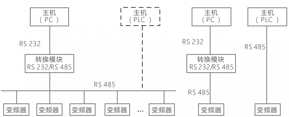
as shown in the figure below, Variable Frequency Drive (As a slave station) There are two ways to network: Single host/multi slave mode, Single host/single slave mode.
Interface method
RS485interface: asynchronous, Half-duplex. Default: 1-8-N-2 (1Starting position, 8bit data bit, No verification, 2Stop position) ,
19200bps, RTU, From address0x0A. Parameter settings can be found inFbGroup Function Code Description.
Communication method
1) The communication protocol for the frequency converter isModbusagreement, SupportRTUandASCIIProtocol format.
2) The frequency converter is a slave, Master-slave point-to-point communication. When the host sends commands using a broadcast address, The slave does not respond.
3) In multi machine communication or long-distance situations, Connect the positive and negative terminals of the signal line for communication at the main station in parallel (100~120) Ohmic resistance can improve the immunity of communication.
4) The frequency converter only providesRS485An interface, If the communication port of the external device isRS232When,Additional neededRS232/RS485
Conversion equipment.
Protocol Format
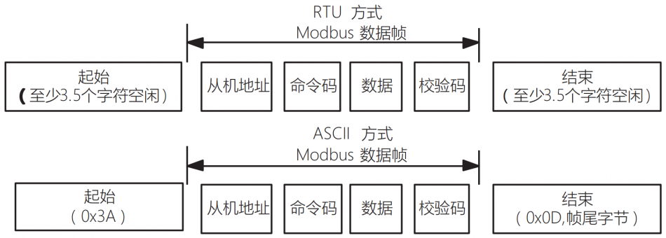
ModbusThe protocol supports bothRTUMethod andASCIIway, The corresponding frame format is shown in the following figure.
ModbusProtocol Format
RTUway
inRTUUnder the method, The idle time between frames is set by the function code andModbusThe larger of the internal agreed values. ModbusThe minimum inter frame idle time agreed internally is as follows: The idle time of the frame header and footer through the bus shall not be less than3.5Define frames based on byte time. Data verification adoptsCRC-16, The entire information is involved in verification, The high and low bytes of the checksum need to be exchanged before sending. specificCRCPlease refer to the example following the protocol for verification. It is worth noting that, Maintain at least inter frame consistency3.5A bus of one character should be idle, The bus idle between frames does not need to accumulate the start and end idle.
The following example is used forRTURead the internal register of slave 5 in the mode0x0101 (F1.01) parameters.
Request frame:

Response frame:

among which, The verification code isCRCchecksum.
ASCIIway
inASCIIUnder the method, The frame header is“0x3A”, The default at the end of the frame is“0x0D, 0x0A”, The end of the frame can also be configured and set by the userIn
Under this method, Except for the frame header and footer, The remaining data bytes are all inASCIICode sending method, First, send the upper 4 bytes,
Then send the lower 4 bytes. ASCIIThe data in the mode is 7 bits in length. Regarding“A”~“F”, Using its capital lettersASCIIThe code.
At this time, the data is usedLRCVerification, Verification covers from point to point. The checksum is equal to all the data involved in the verification process
Characters and (Discard carry bits) The complement code.
The following example is used forASCIIWriting Method4000 (0xFA0) To the internal registers of slave 50201 (F2.01) .
Request frame:

among which, The verification code isLRCchecksum, Its value is equal to (05+06+02+01+0x0F+0xA0) The complement code.
Response frame:

The frequency converter can set different response delays through function codes to meet the specific application needs of various main stations, RegardingRTUThe actual response delay of the mode is not less than3.5Character interval, RegardingASCIIThe actual response delay of the mode is not less than1ms.
Protocol application
Modbuscommand code
ModbusThe main function is to read/write the functional parameters of the frequency converter, Different command codes determine different operation requests. Variable Frequency DriveModbusThe protocol supports the operations listed in the table below.

Mapping rules for functional parameter addresses of frequency converters
The group number mapping of the functional parameters of the frequency converter ismodbusHigh byte of register address (0~Fcorresponding value0x00~0x0F) , Intra group index (The sequence number of the parameter within the group) Map toModbusLow byte of register address (00~99correspond to0x00~0x63) , When data only needs to be saved toRAMIn the middle(Do not save data in case of power failure)When,Move the highest position of the address“1”. for example: Communication modification frequency value, You can modify the functional parametersF0.05Implement.
Functional Parameters“F0.05” (Digital frequency setting value) The corresponding register address is“0x0005”:
1) When data is only savedRAMWhen,The corresponding address is ”0x8005”.
2) When data needs to be saved toEEPROMSave data in case of power failure)When,The corresponding address is “0x0005”.
Remark:
When frequent modification of the set frequency is required, And there is no need to power down to save this parameter, Suggest adopting the first method, Only save toRAMIn the middle,Can be extendedEEPROMservice life.
Obtain the parameter properties of the frequency converter function code
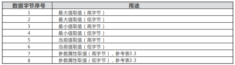
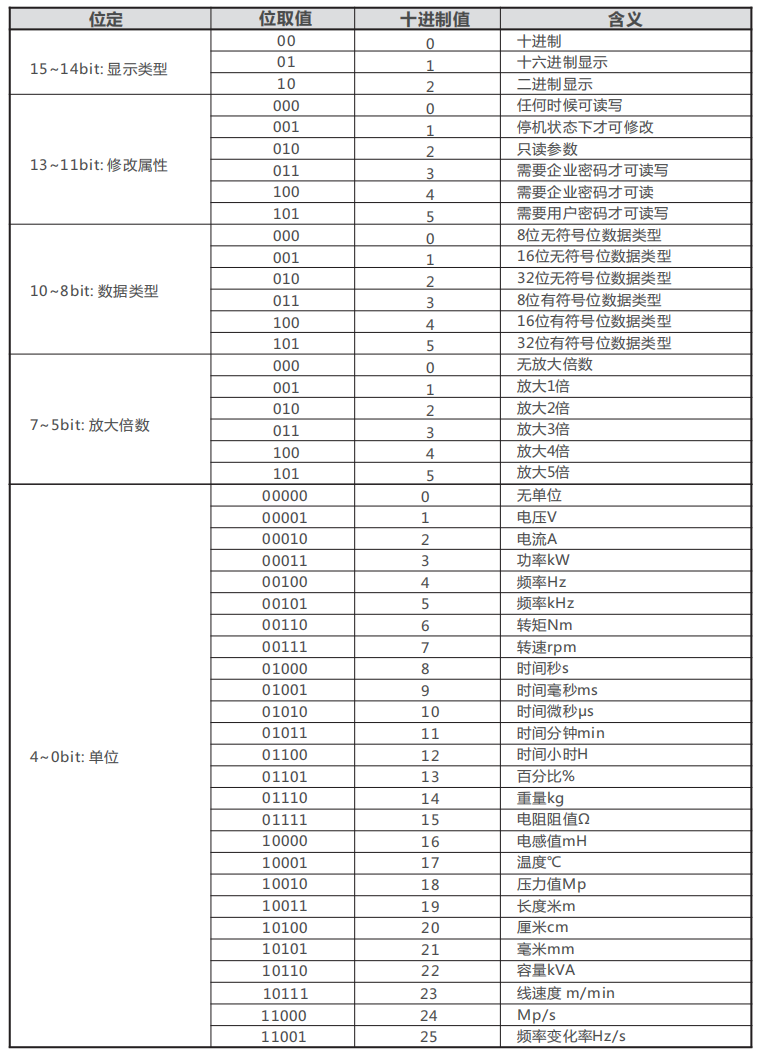
can pass through0x04Command code to obtain the parameter attributes corresponding to the function code parameters of the frequency converter, The format of attribute definition is shown in the table:
Attention:
The parameter attribute contains 4 (Or 5) 16Bit data value, The number of registers should be4(or 5)Integer multiples of, Otherwise, there will be an error in the communication feedback of illegal register values.
control command, status information, Fault information
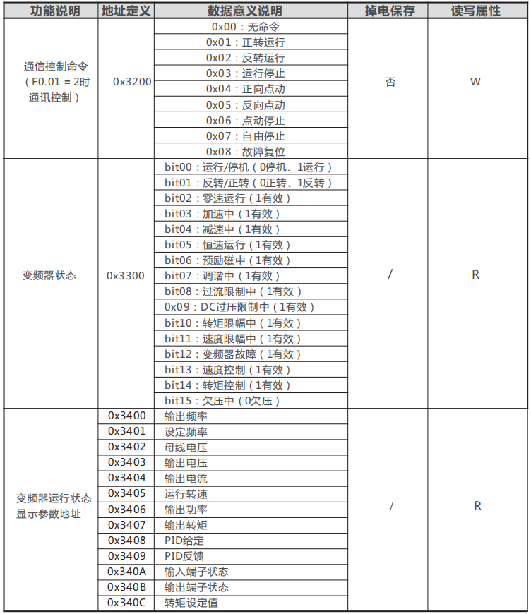
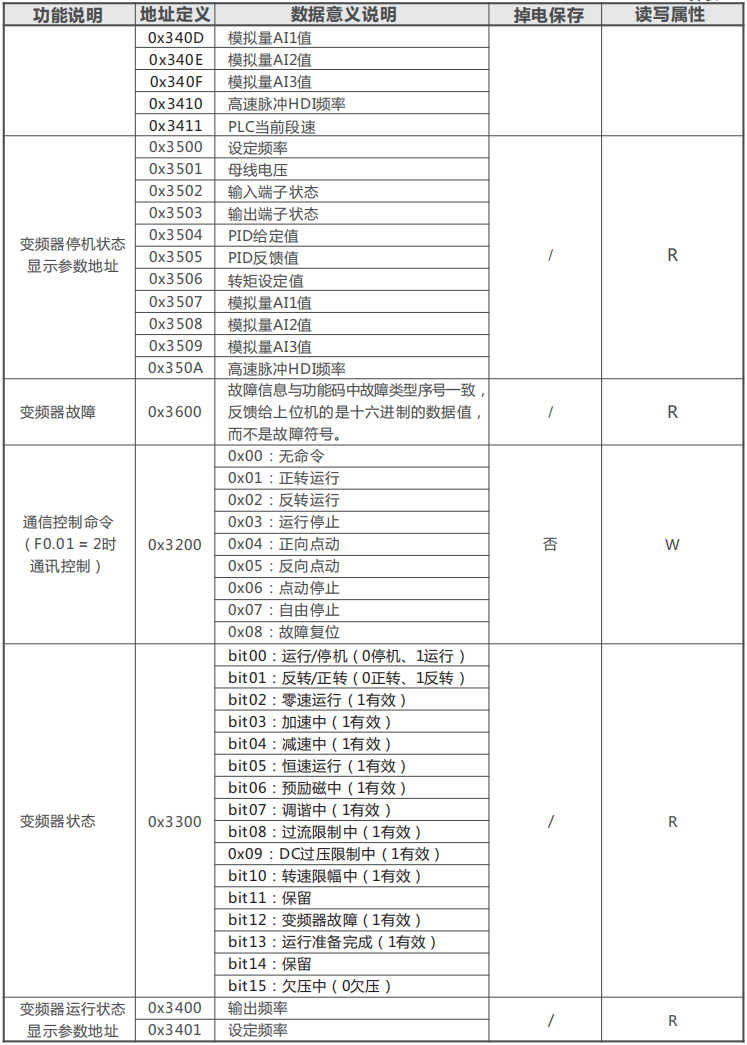
ModbusThe main station can start the controlled frequency converter through control commands, Stop, Setting the operating frequency and other operations. Retrieve the status parameter information of the frequency converter through the corresponding command(For example:operating frequency, Output current, Output torque and other parameters) , At the same time, it can monitor the fault information of the controlled frequency converter. (Reference for General Parameter Address Mapping Rules3.5.2),Detailed description of special control parameters in the table below.
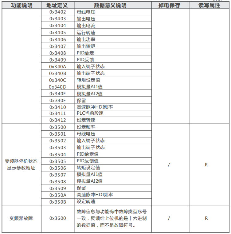
parameter management
ModbusThe main station can obtain corresponding commands fromCPUObtain the number and group number values of system parameters in the board, And obtain the intra group number of the corresponding group. The specified communication function code is0x03”,The definition of communication address is shown in the table
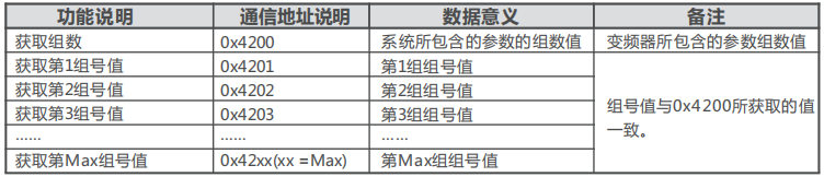

Wiring Instructions
topological structure
No repeater configuredRS-485-ModbusThere is a direct connection to all devices (Chrysanthemum shaped) Or trunk cables connected through short branch cables.
Trunk cable, Also known as bus, It may be very long. Its two ends must be connected to the line terminals. It can also be in multiple locationsRS-485ModbusUse repeaters between them. And each slave address in the network has a unique address, This is a guaranteeModbusThe foundation of serial communication.
Length
The end-to-end length of trunk cables must be limited. Maximum length and baud rate, Cable (Specifications, Capacitance or characteristic impedance) , The number of loads and network configuration on the daisy chain (2Line or 4-wire system) concerning.
For high-speed baud rates9600bps, AWG26 (Or thicker) For cables of different specifications, Its maximum length is1000m.
Branches must be short, must not exceed20m. If using a multi port splitter with n branches, The maximum length of each branch must be limited to40mdivided byn.
Grounding form
Must“Public End”circuit (Common terminal for signal and optional power supply) Directly connected to the protected ground, Ideally, the entire bus should be grounded at a single point. Usually, This point can be selected on the main station or its branch.
Cable
On the serial linkModbusThe cable must be shielded. At one end of each cable, Its shielding must be connected to the protective ground. If a connector is used on this end, Connect the connector housing to the cable shielding layer. RS485-ModbusA pair of balanced wires and a third wire must be used (Used for public end) .
CorrectRS485-ModbusSpeaking of, A sufficiently wide cable diameter must be selected to allow for the use of the maximum length (1000m) .
AWG24Can satisfyModbusThe need for data transmission.
Definition of Communication Exception Code
When corresponding error messages are detected during the communication process, lower-level device(i.eCPUBoard)Will place the high position of the function code“1”, And provide corresponding error codes as feedback (Exception Code) , In order for the upper computer to identify the current cause of the error, The corresponding definitions are shown in the table
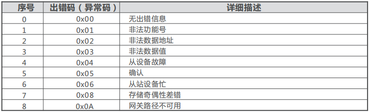
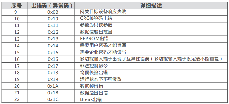
ModbusExamples of Communication
Set up relevant communication function parameters before communication, Provide communication addresses between the upper and lower computers, Baud rate, Consistent data format, etc.
Example 1:
If it is necessary to change the starting frequency setting of the frequency converter, will50.00Hzchange to25.00Hz.
Data sent by the host:
| Inverter address | Write command | parameter address | Data content | CRCVerification |
| 01 | 06 | 00 05 | 09 C4 | 9E 08 |
Data received by the host:
| Inverter address | Write command | parameter address | Data content | CRCVerification |
| 01 | 03 | 00 05 | 09 C4 | 9E 08 |
Example 2:
If it is necessary to read the frequency converterF0.00Group control method.
Data sent by the host:
| Inverter address | Read command | parameter address | Number of data | CRCVerification |
| 01 | 03 | 00 00 | 00 01 | 84 0A |
Data received by the host:
| Inverter address | Read command | parameter address | Data content | CRCVerification |
| 01 | 03 | 02 | 00 02 | 39 85 |
Example 3:
If the input command exceeds the range of function code parameter settings, in order toF0.01 (Run command channel selection) Group as an example, If the input command is4, Exceeding the set range0~2, So there will be incorrect response messages.
Data sent by the host:
| Inverter address | Write command | parameter address | Data content | CRCVerification |
| 01 | 06 | 00 01 | 00 04 | D9 C9 |
Data received by the host:
| Inverter address | Error response code | error code | Data content | CRCVerification |
| 01 | 86 | 12 | 00 02 | C2 6D |


Leave a Reply