

Communication Function
The instrument adopts RS485 communication mode, and the baud rate can be set to 1200, 2400bps, 4800bps, and 9600bps.
Up to 32 instruments can be connected simultaneously on the same communication line, and each instrument can set its communication address. The communication connection should use shielded twisted pair cables with copper mesh, and the wire diameter should not be less than 0.5mm2. When wiring, the communication line should be kept away from strong electrical cables or other strong electric field environments, with a maximum transmission distance of 1200m. The typical network connection method is shown in the figure, and users can choose other suitable connection methods according to specific situations.

The data frame for switching from DL/T 645-2007 protocol to ModBus RTU communication protocol is as follows:
FE FE FE FE 68 xx xx xx xx xx xx 68 14 0E 33 33 35 3D 35 33 33 33 33 33 33 33 33 33CS 16
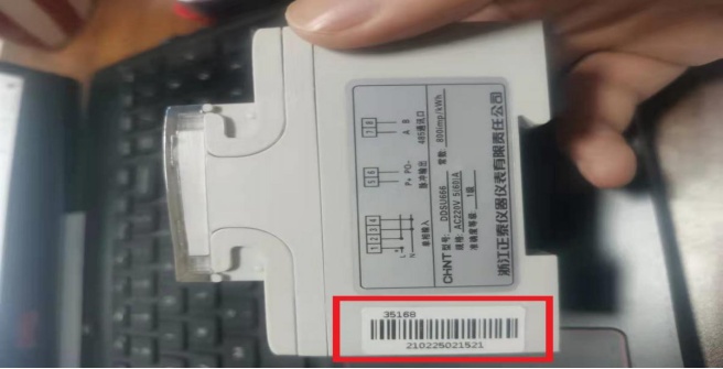
Note: xx xx xx xx xx xx is the screen display address. If the number is 21 02 25 02 15 21, fill in 21 15 02 25 02 21, and fill in the reversed barcode number on the instrument side
CS is the last two bits of the checksum from 68 xx xx to 33 33 33, excluding the first four FEs;
The modified Modbus address, baud rate, data bits, checksum, and stop bits are displayed on the instrument screen.
The default DL/T645 connection parameter is (8n22400bps). Send the above command and observe the meter screen display. When "DLT645" changes to "Modbus", it means the switch is successful. Observe the number on the screen after the "Modbus" display, which is the Modbus slave address of the meter, displayed in decimal. Note that the default baud rate of Modbus is 9600. When the instrument is set to ModBus RTU transmission mode, the ModBus RTU communication protocol adopts a master-slave response communication connection method on one communication line. Firstly, the signal from the host computer is addressed to a terminal device (slave) with a unique address, and then the response signal sent by the terminal device is transmitted to the host in the opposite direction, that is, in half duplex working mode. This protocol only allows communication between hosts (PCs, PLCs, etc.) and terminal devices, and does not allow data exchange between independent terminal devices. This way, each terminal device will not occupy the communication line during their initialization, but only respond to query signals that arrive locally. The instrument provides ModBus RTU communication protocol (see Appendix A), and the parameter information that can be read or modified through communication is shown in the table below.
When the instrument is set to ModBus RTU transmission mode, the ModBus RTU communication protocol adopts a master-slave response communication connection method on one communication line. Firstly, the signal from the host computer is addressed to a terminal device (slave) with a unique address, and then the response signal sent by the terminal device is transmitted to the host in the opposite direction, that is, in half duplex working mode. This protocol only allows communication between hosts (PCs, PLCs, etc.) and terminal devices, and does not allow data exchange between independent terminal devices. This way, each terminal device will not occupy the communication line during their initialization, but only respond to query signals that arrive locally.
The instrument provides ModBus RTU communication protocol (see Appendix A), and the parameter information that can be read or modified through communication is shown in the table below.
| Parameter Address | Parameter Code | Parameter Description | Data Type | Data Length Word | Read/Write Properties |
| 0000H | UcodE | Programming Password CodeE | int | 1 | R |
| 0001H | REV. | Software Version | int | 1 | R/W |
| 0002H | CLrE | Energy Clearing CLr. E | int | 1 | R/W |
| 0003H | RESERVED | Reserve | int | 1 | R/W |
| 0004H | RESERVED | Reserve | int | 1 | R/W |
| 0005H | ChangeProtocol | Protocol switching settings | int | 1 | R/W |
| 0006H | Addr | This address is only valid when using Modbus RTU | int | 1 | R/W |
| 0007H | RESERVED | Reserve | int | 1 | R/W |
| 0008H | RESERVED | Reserve | int | 1 | R/W |
| 0009H | RESERVED | Reserve | int | 1 | R/W |
| 000AH | RESERVED | Reserve | int | 1 | R/W |
| 000BH | RESERVED | Reserve | int | 1 | R/W |
| 000CH | BAud | Baud rate | int | 1 | R/W |
| 000DH | RESERVED | Reserve | int | 1 | R/W |
| 000EH | RESERVED | Reserve | int | 1 | R/W |
| 000FH | RESERVED | Reserve | int | 1 | R/W |
| 0010H | RESERVED | Reserve | int | 1 | R/W |
| 2000H | U | A-phase voltage | float | 2 | R/W |
| 2002H | I | A-phase current | float | 2 | R/W |
| 2004H | P | Instantaneous total active power | float | 2 | R/W |
| 2006H | Q | Instantaneous total reactive power | float | 2 | R/W |
| 2008H | S | Instantaneous total apparent power | float | 2 | R/W |
| 200AH | PF | Total power factor | float | 2 | R/W |
| 200CH | RESERVED | Reserved | float | 2 | R/W |
| 200EH | Freq | Grid frequency | float | 2 | R/W |
| 2010H | RESERVED | Reserved | float | 2 | R/W |
| 4000H | Ep | Active total energy | float | 2 | R/W |
ChangeProtocol switching mode word, data 2 is Modbus RTU protocol, data 1 is DL/T 645-2007 protocol;
CLr. E electric energy reset write 1 to clear the total electric energy;
Baud baud rate: 0:1200bps; 1:2400bps; 2:4800bps; 3:9600bps;
Communication Example
Function Code 03H: Read Register
The host needs to read data from two registers with a slave address of 01H and a starting register address of 0CH. The host sends:
| Address Code | Function Code | Starting Register Address | Register Quantity | CRC Check Code |
| 01 | 03 | 00 0C | 00 02 | 04 08 |
If the data in the slave registers 0CH and 0DH are 0000H and 1388H, the slave returns:
| address code | function code | byte count | Register 0CH data | Register 0DH data | CRC check code |
| 01 | 03 | 04 | 00 00 | 13 88 | F7 65 |
Function code 10H: Write to multiplex register
For example, the host needs to save data 0002H, 1388H, and 000AH to three registers with slave address 01H and starting register address 00H.
Host sends:
| Address code | Function code | Start register address | Number of registers | Number of bytes written | 00H Register to be written data | 01H Register to be written data | 02H Register to be written data | CRC check code |
| 01 | 10 | 00 00 | 00 03 | 06 | 00 02 | 13 88 | 00 0A | 9B E9 |
Slave return:
| Address code | Function code | Starting register address | Number of registers | CRC check code |
| 01 | 10 | 00 00 | 00 03 | 80 08 |
16 bit CRC checksum
The host or slave can use the checksum to determine whether the received information is correct. Due to electronic noise or other interference, errors may occur during the transmission of
information. The checksum can verify whether the communication information between the host or slave is incorrect. The 16 bit CRC checksum is calculated by the host and placed at the end of the transmitted information frame. Re calculate the CRC of the received information from the slave, compare the calculated CRC with the received CRC to see if they are consistent. If they are not consistent, it indicates an error. Only 8 data bits are used for CRC calculation, and the start and stop bits do not participate in CRC calculation.
The 16 bit CRC checksum is calculated by the host and placed at the end of the transmitted information frame. Re calculate the CRC of the received information from the slave, compare the calculated CRC with the received CRC to see if they are consistent. If they are not consistent, it indicates an error. Only 8 data bits are used for CRC calculation, and the start and stop bits do not participate in CRC calculation.
The calculation method for CRC check code is as follows:
1) Preset one 16 bit register as hexadecimal FFFF (i.e. all 1s), and call this register CRC register;
2) Place the first 8-bit binary data (the first byte of the communication information frame) that is different from the lower 8-bit OR of the 16 bit CRC register, and place the result in the CRC register;
3) Move the content of the CRC register to the right by one bit (towards the lower bit) and fill the highest bit with 0, and check the shifted bit after the right shift;
4) If the displacement is 0: repeat step 3) (move one more position to the right);
If the offset is 1: XOR the CRC register with polynomial A001 (1010 0000 0000 0001);
5) Repeat steps 3) and 4) until the entire 8-bit data is processed by shifting to the right 8 times;
6) Repeat steps 2) to 5) to process the next byte of the communication information frame; After calculating all bytes (excluding CRC checksum) of the communication information frame according to the above steps, the content of the CRC register obtained is the 16 bit CRC checksum.
7) After calculating all bytes (excluding CRC checksum) of the communication information frame according to the above steps, the content of the CRC register obtained is the 16 bit CRC checksum.
Error Handling
When the instrument detects errors other than CRC check code errors, it will send a message back to the host. The highest position of the function code is 1, which means that the function code sent from the slave to the host is based on the function code sent by the host plus 128. The error message frame format returned by the slave is as follows:
| Address code | Function code (highest bit is 1) | Error code | CRC check code |
| 1 byte | 1 byte | 1-byte | 2-byte |
Error code as follows:
| 01H | Illegal function code | Received function code instrument does not support |
| 02H | Illegal register address | Received register address exceeds instrument's register address range |
| 03H | Illegal data value | Received data value exceeds corresponding address's data range |
Modbus Technology Communication QQ Group



Leave a Reply