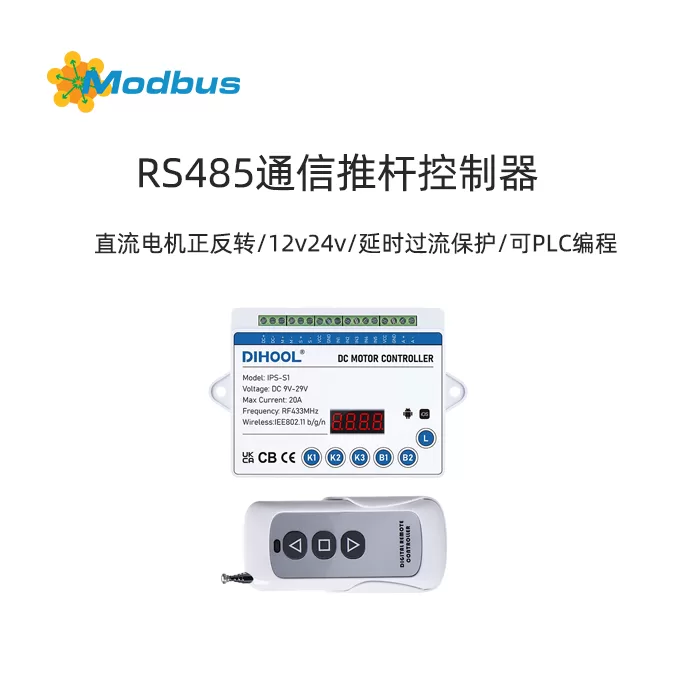
1. Product Overview
The new S1 controller is a brand new product that has undergone deep modifications based on the latest version of S2, and is not directly related in terms of functionality and design to the old S1. It inherits most of the features of the S2 new version program, such as slow start and slow stop, but removes the WIFI module and its related networking functions. The new S1 controller has undergone comprehensive upgrades in voltage range, interface functionality, communication capabilities, and other aspects, aiming to meet a wider range of industrial automation control needs.
2, Product Features
(1) Electrical performance upgrade
- Voltage Range: The new S1 controller supports a voltage range of 10V-48V, which is more widely applicable compared to the old version of the product and can be compatible with more types of power equipment. At the same time, the withstand voltage values of related devices have also been upgraded to ensure stable operation in high voltage environments.
- Current carrying capacity: The maximum current carrying capacity of the controller is 10A, which can meet the driving requirements of high-power motors and is suitable for motor control scenarios with medium loads.
(II) Function optimization and adjustment
- Removing WIFI module: The new S1 controller has removed the EasyLink WIFI module, so it no longer has networking function. The original WIFI pairing key and WIFI indicator light have been changed to remote pairing key and 433 learning indicator light respectively to meet the new functional requirements.
- Adjustment of 433 receiving moduleThe position of the 433 receiving module has been moved from its original position to the position of the original EasyLink WIFI module, while its function remains unchanged. However, the logic of the indicator light remains consistent with the light on the 433 receiving board, making it easier for users to intuitively judge the working status of the module.
- Added 485 serial communication function: The new S1 controller has added RS485 serial communication function, which enables the query and setting of motor status, limit, PWM duty cycle and other parameters through register instructions. The specific functions of the register are as follows:
- Register 0: Query the motor status (1 indicates stop, 2 indicates forward rotation, 4 indicates reverse rotation).
- Register 1: Run instruction (1 represents stop, 2 represents forward rotation, 4 represents reverse).
- Register 2: Query the limit status of IN3 (0 indicates that the limit has been activated, 1 indicates that the limit has not been activated).
- Register 3: Query the limit status of IN4 (0 indicates that the limit has been activated, 1 indicates that the limit has not been activated).
- Register 4: Query/modify device number (range 1-255).
- Register 5: Read/set the inverted PWM duty cycle (range 20-93, used for voltage regulation).
- Register 6: Read/set the forward PWM duty cycle (range 20-93, used for voltage regulation).
- Register 7: Set the forward and reverse PWM duty cycle (range 20-93, used for voltage regulation).
- Register 8: Query the current value of the motor (in mA).
- Add 485 terminal resistorA 120 Ω terminal resistor is reserved on the board, and users can activate the terminal resistor by short circuiting the reserved empty solder pad to optimize the signal integrity of the RS485 communication link.
- New interfaceAdded a 3P-2.54-Bead female interface for RS485 A+, B -, GND signal connections. The remaining interfaces are consistent with S2, including DC bus, M+, M -, IN5, VCC (12V 300mA), IN1 (forward rotation), IN2 (reverse rotation), IN3 (reverse rotation limit), IN4 (forward rotation limit).
(3) Communication Protocol
The new S1 controller uses Modbus protocol for RS485 communication. Here are some typical instruction formats and descriptions:
- Check the status of the motor:
- Sending message: 01 03 00 00 01 84 0A
- Response message:
- Stop: 01 03 02 00 01 79 84
- Forward rotation: 01 03 02 00 02 39 85
- Reverse: 01 03 02 00 04 B9 87
- Write stop command:
- Sending message: 01 06 00 01 00 01 19 CA
- Response message: 01 06 00 01 00 01 19 CA
- In3 limit inquiry:
- Send message: 01 03 00 02 00 01 25 CA
- Response message:
- The limit has taken effect: 01 03 02 00 B8 44
- Limit not in effect: 01 03 02 00 01 79 84
- In4 limit inquiry:
- Sending message: 01 03 00 03 00 01 74 0A
- Response message:
- The limit has taken effect: 01 03 02 00 B8 44
- Limit not effective: 01 03 02 00 01 79 84
- Query device number:
- Send message: 01 03 00 04 00 01 C5 CB
- Response message: 01 03 02 00 01 79 84
- Write device number:
- Send message: 01 06 00 04 00 02 49 CA
- Response message: 01 03 02 00 02 39 85
- Query reverse PWM duty cycle:
- Send message: 01 03 00 05 00 01 94 0B
- Response message: 01 03 02 00 5D 79 BD (representing 93% duty cycle)
- Write reverse PWM duty cycle:
- and send message: 01 06 00 05 00 5D 58 32
- Response message: 01 06 00 05 00 5D 58 32
- Query forward PWM duty cycle:
- Send message: 01 03 00 06 00 01 64 0B
- Response message: 01 03 02 00 5D 79 BD
- Write forward PWM duty cycle:
- Send message: 01 06 00 06 00 5D A8 32
- Response message: 01 06 00 06 00 5D A8 32
- Write forward and reverse PWM duty cycle:
- Send message: 01 06 00 07 00 5D F9 F2
- Response message: 01 06 00 07 00 5D F9 F2
- Query the current motor Current value:
- Send message: 01 03 00 08 00 01 05 C8
- Response message: 01 03 02 00 B8 44
III. Installation and commissioning
(1) Hardware installation
- Power connection: Connect the power cord to the DC bus and ensure that the input voltage is within the range of 10V-48V.
- Motor Connection: Connect the forward and reverse control lines of the motor to the IN1 and IN2 interfaces respectively, and connect the limit signal line to the IN3 and IN4 interfaces.
- RS485 Communication Connection: Use the 3P-2.54-Bead female interface to connect the RS485 communication line, ensuring that the A+, B -, and GND signals are correctly connected. If terminal resistors need to be enabled, short-circuit the reserved empty solder pads.
- Remote pairing: Press the remote pairing button to complete the pairing operation between the remote control and the controller.
(II) Software Debugging
- Device Number Setting: Through RS485 communication, use Modbus protocol to write instructions to set the device number (register 4), ensuring that each controller has a unique device number on the communication link.
- PWM duty cycle setting: According to actual needs, set the reverse PWM duty cycle (register 5), forward PWM duty cycle (register 6), and forward reverse PWM duty cycle (register 7) by writing instructions to achieve motor voltage regulation control.
- Function Test: Send operation instructions (Register 1) to control the motor to rotate forward, reverse, and stop, query the motor status (Register 0), limit status (Register 2 and Register 3), and current value (Register 8), and verify whether the controller function is normal.
IV. Precautions
- Power Supply Voltage: Please ensure that the input power supply voltage is within the range of 10V-48V to avoid damage to the controller due to high or low voltage.
- RS485 Communication: In the RS485 communication link, ensure that the terminal resistors are correctly enabled to avoid signal reflection and communication interference.
- Remote pairing: The remote pairing button is only used for pairing the remote control with the controller. After pairing is completed, this button has no other functions.
- Limit Function: When using the limit function, ensure that the limit signal line is connected correctly and verify whether the limit function is working properly by querying the limit status (register 2 and register 3).
- PWM duty cycle range: When setting the PWM duty cycle, please ensure that the value is within the range of 20-93. Exceeding this range may cause abnormal motor control.
V. After sales Service
If you encounter any problems during use, please contact our after-sales service center in a timely manner. We will provide you with professional technical support and after-sales service to ensure the normal operation of your equipment.


Leave a Reply