
This article introduces the detailed installation and wiring of Siemens PLCs, including PLC models such as Smart200, S7-300, S7-1200, and S7-1500.
PART 01
Common PLC wiring diagram for Siemens 200 modules
CPU SR20+EMDR32
 PART 02
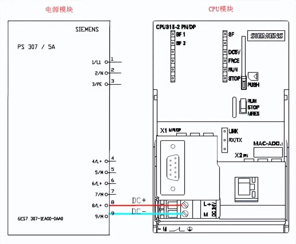
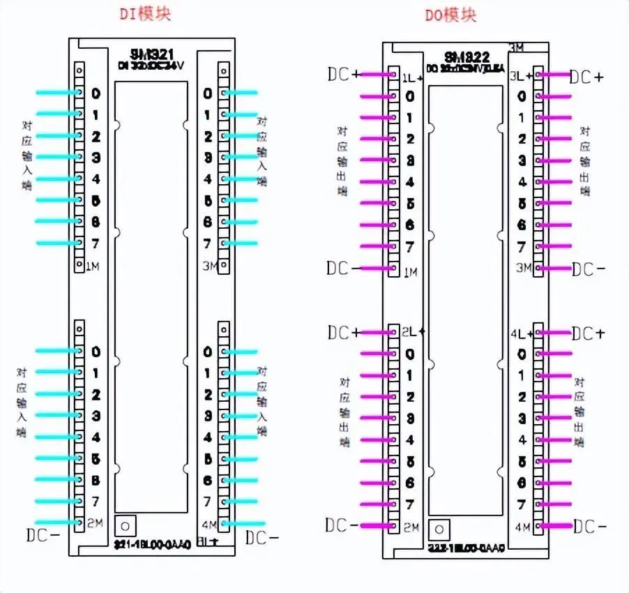
Common module wiring diagram for Siemens S7-300
CPU315+PS307 (power module)+SM321 (DI module)+SM322 (DO module)
PART 02
Common module wiring diagram for Siemens S7-300
CPU315+PS307 (power module)+SM321 (DI module)+SM322 (DO module)
 PART 03
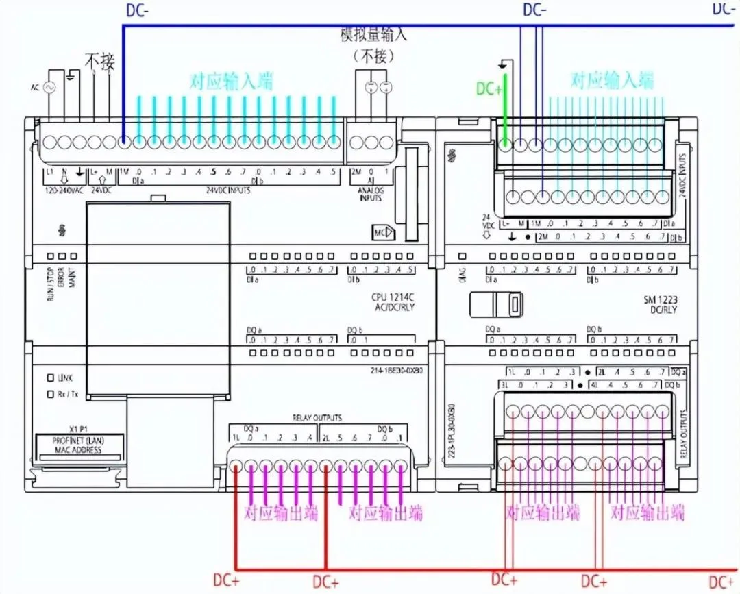
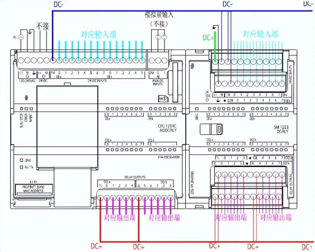
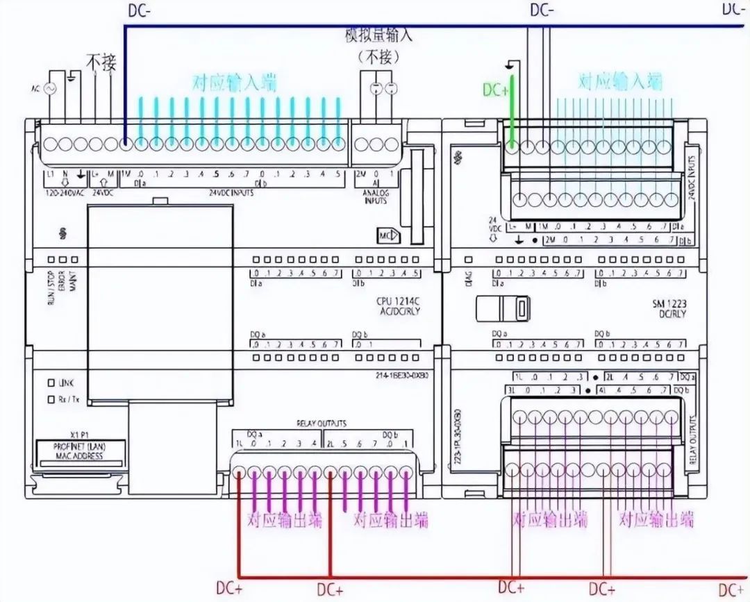
Common module wiring diagram for Siemens S7-1200
CPU1214C+SM1223
PART 03
Common module wiring diagram for Siemens S7-1200
CPU1214C+SM1223
 PART 04
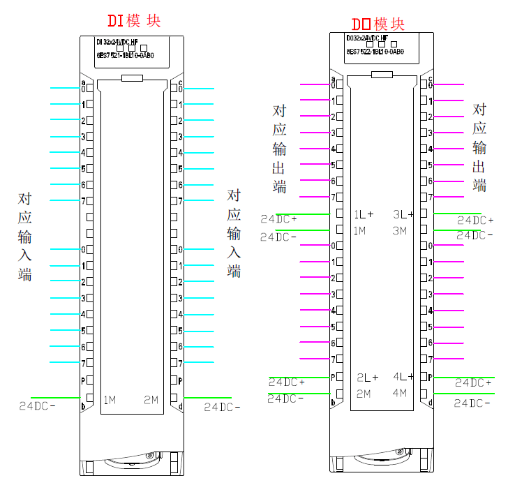
Common module wiring diagram for Siemens 1500
PART 04
Common module wiring diagram for Siemens 1500
 PART 05
The following provides a detailed introduction to the hardware installation and wiring of S71500
Hardware Requirements
● 1 × CPU 1511-1 PN (6ES7511-1AK00-0AB0)
● 1 S7-1500 load current power supply PM 70W 120/230VAC (6EP1332-4BA00)
● 1 mounting rail (6ES7590-1AB60-0AA0)
● 1 digital input module DI 16x24VDC SRC BA (6ES7521-1BH50-0AA0)
● 1 digital output module DQ 16x24VDC/0.5A ST (6ES7522-1BH00-0AB0)
● 2 front connectors (6ES7592-1AM00-0XB0)
● 1 4 MB SIMATIC memory card (e.g. 6ES7954-8LBxx-0AA0)
● 1 Ethernet cable
Software Requirements
● SIMATIC STEP 7 Professional V13 and above
● SIMATIC WinCC Advanced V13 or SIMATIC WinCC Professional V13 and above
Installation steps for assembly components
1. Install the load current power supply (PM) on the installation rail.
PART 05
The following provides a detailed introduction to the hardware installation and wiring of S71500
Hardware Requirements
● 1 × CPU 1511-1 PN (6ES7511-1AK00-0AB0)
● 1 S7-1500 load current power supply PM 70W 120/230VAC (6EP1332-4BA00)
● 1 mounting rail (6ES7590-1AB60-0AA0)
● 1 digital input module DI 16x24VDC SRC BA (6ES7521-1BH50-0AA0)
● 1 digital output module DQ 16x24VDC/0.5A ST (6ES7522-1BH00-0AB0)
● 2 front connectors (6ES7592-1AM00-0XB0)
● 1 4 MB SIMATIC memory card (e.g. 6ES7954-8LBxx-0AA0)
● 1 Ethernet cable
Software Requirements
● SIMATIC STEP 7 Professional V13 and above
● SIMATIC WinCC Advanced V13 or SIMATIC WinCC Professional V13 and above
Installation steps for assembly components
1. Install the load current power supply (PM) on the installation rail.
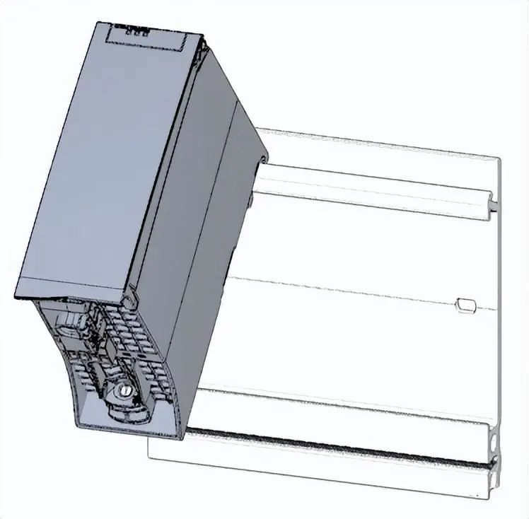 2. Open the front cover and unplug the power connection plug.
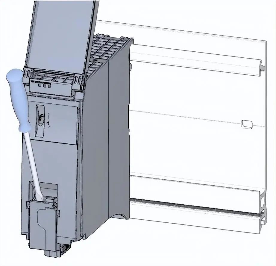 3. Unplug the 4-pin connection plug and tighten the load current power supply (PM).
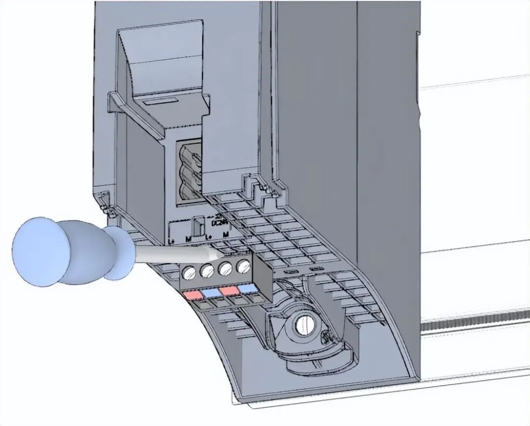 4. Insert the U-shaped connector into the back of the CPU.
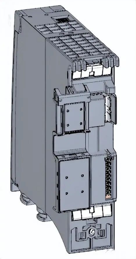 5. Install the CPU on the installation rail and tighten it.
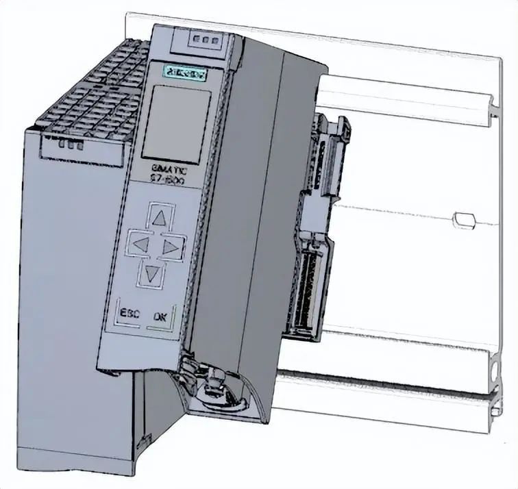 6. Insert the U-shaped connector into the back of the digital input module.
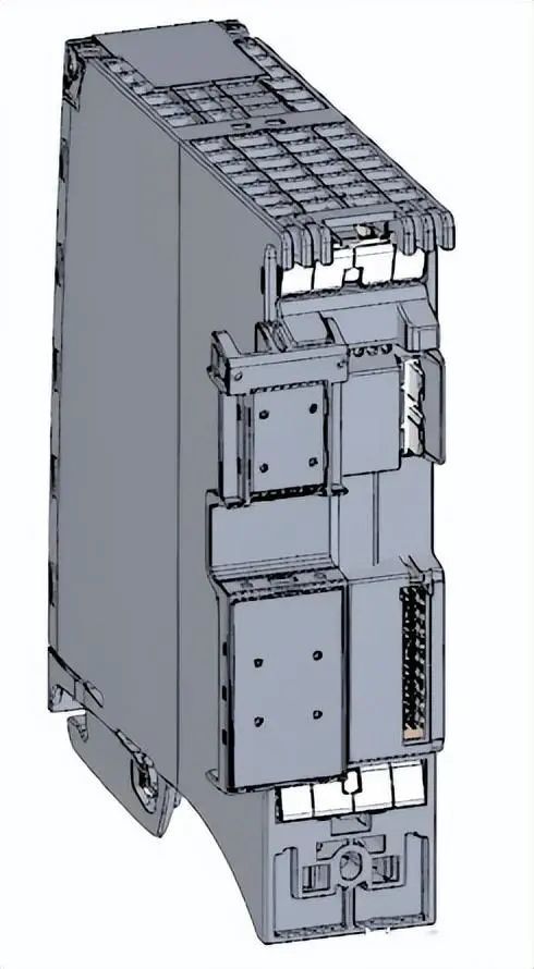 7. Connect the digital input module to the installation rail and tighten it.
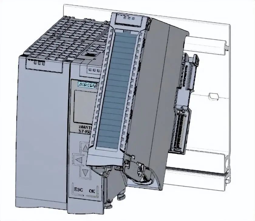 8. Connect the digital output module to the installation rail and tighten it.
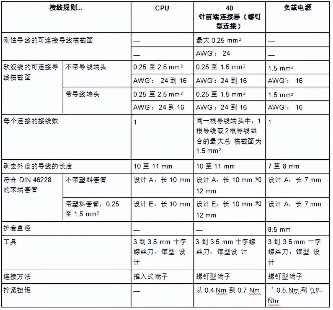
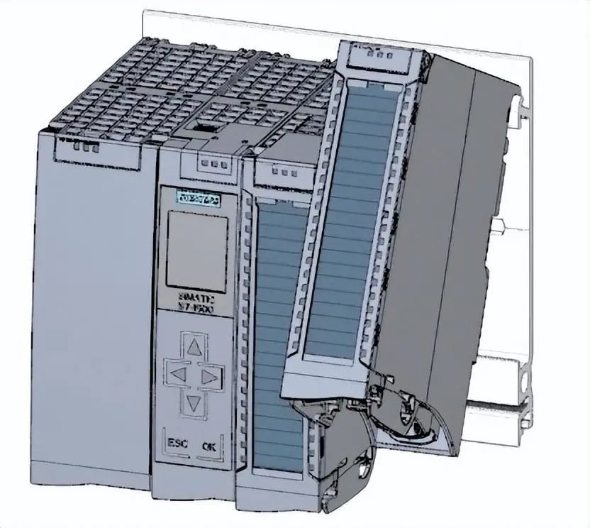 Wiring rules for CPU
 Wiring steps for power connection plug
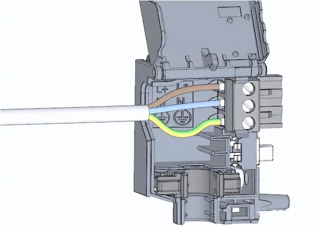
1. Use a suitable tool to pull out the connector cover.
Wiring steps for power connection plug
1. Use a suitable tool to pull out the connector cover.
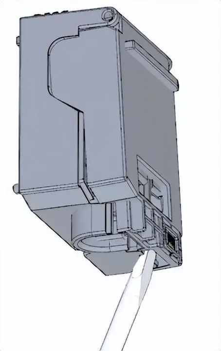 2. Connect the power cord to the plug according to the wiring diagram. On the other side of the plug, there is information indicating the voltage that can be used after the plug is certified. According to the information on the back of the plug, select the corresponding voltage by inserting the coding component.
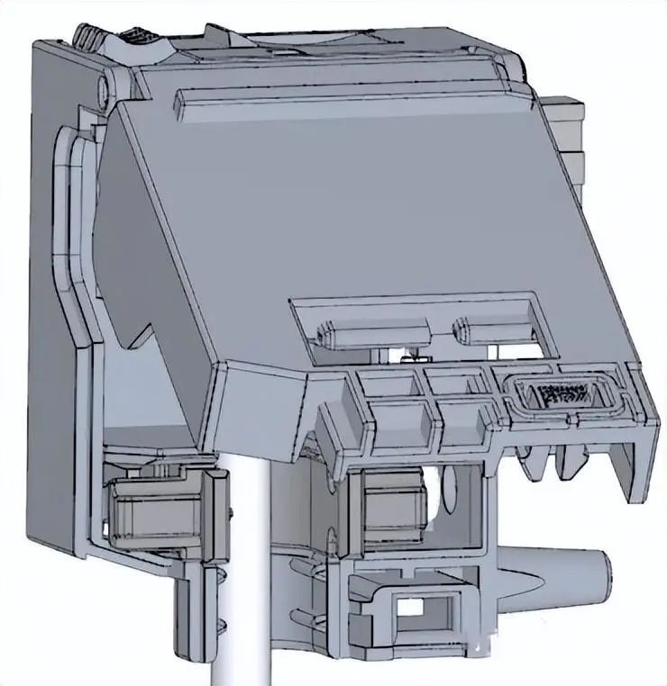
 3. Close the cover.
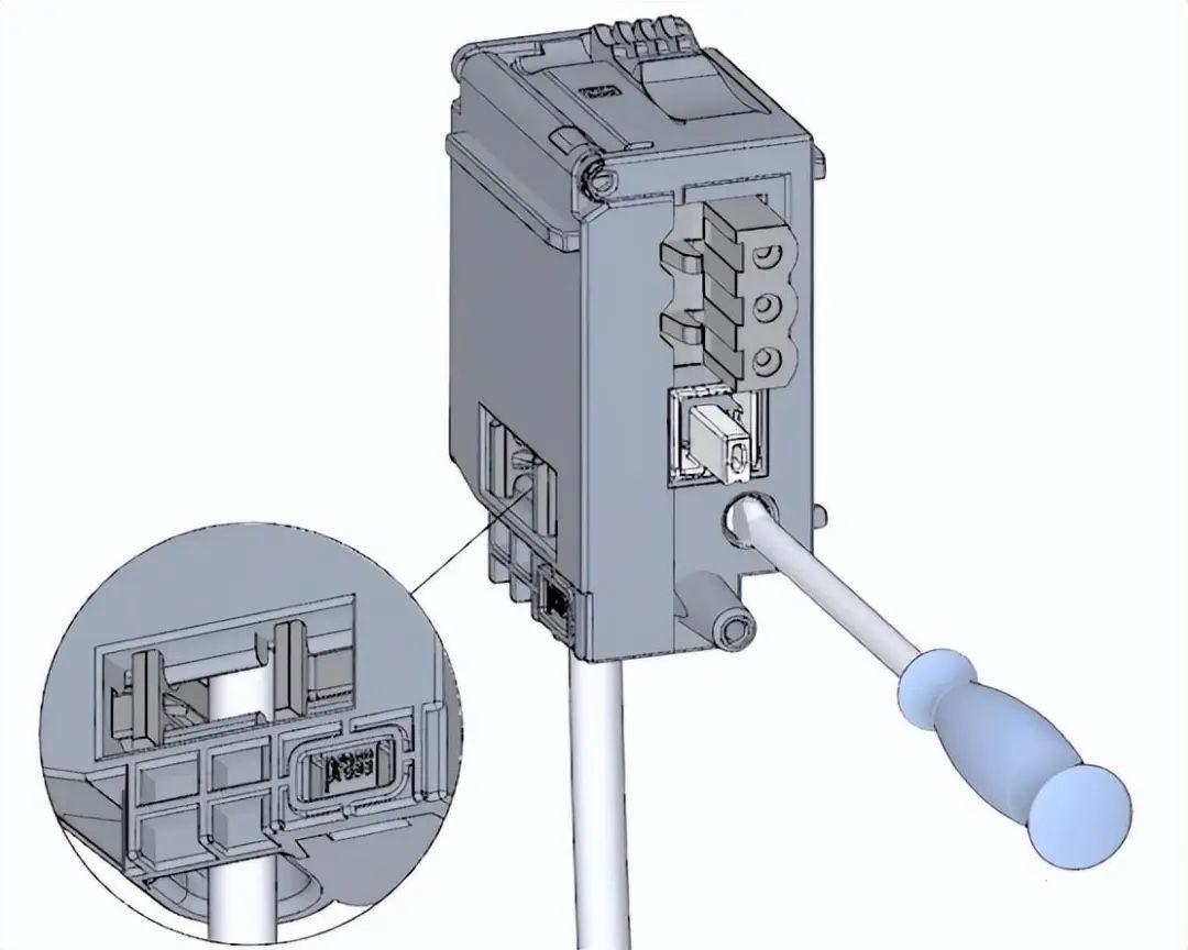
 4. Tighten the screw on the power connection plug.
 Connect the load current power supply (PM) to the CPU steps
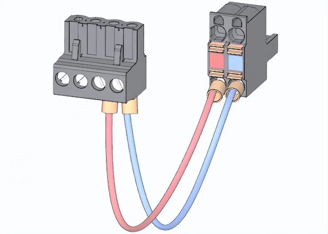
1. Wire the 4-pin connector plug of the load current power supply (PM).
Connect the load current power supply (PM) to the CPU steps
1. Wire the 4-pin connector plug of the load current power supply (PM).
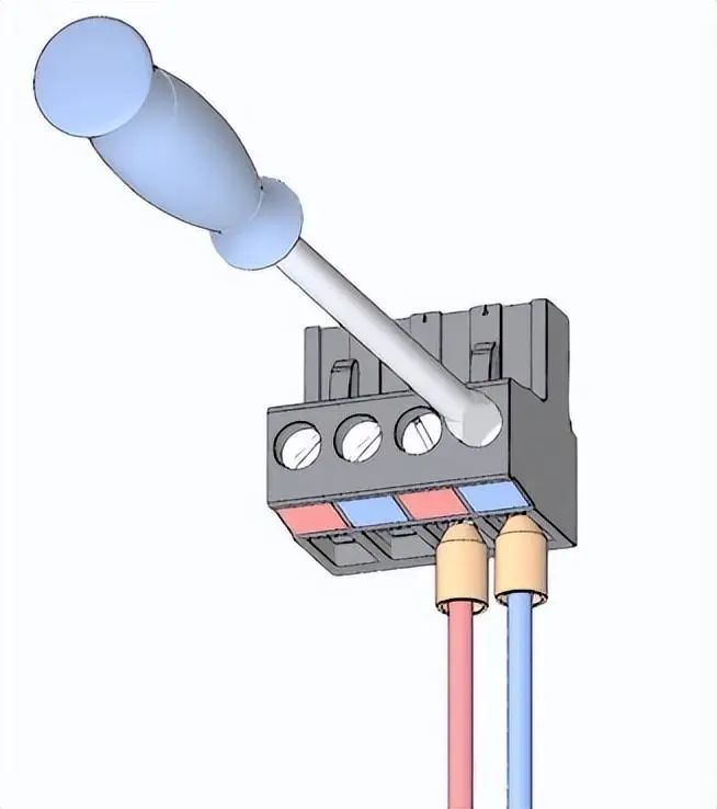 2. Connect the 4-pin connector plug to the 4-pin power connection plug of the CPU.
 Wiring steps for digital input module
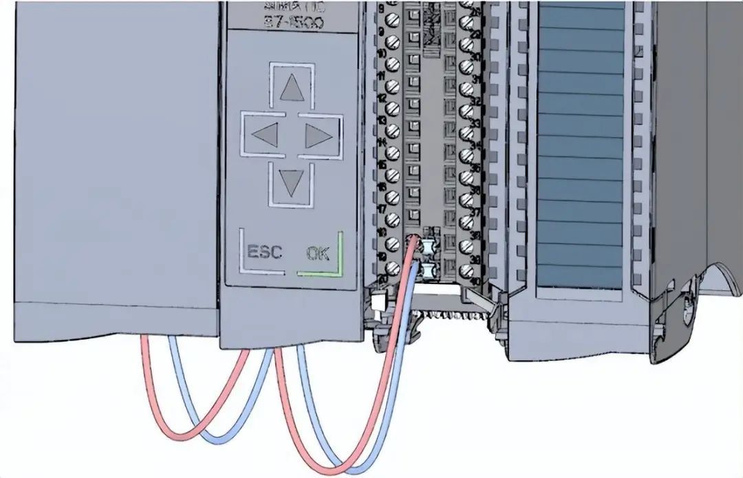
1. Insert the front connector into the prewired position. At the prewired position, there is no electrical connection between the front connector and the module.
Wiring steps for digital input module
1. Insert the front connector into the prewired position. At the prewired position, there is no electrical connection between the front connector and the module.
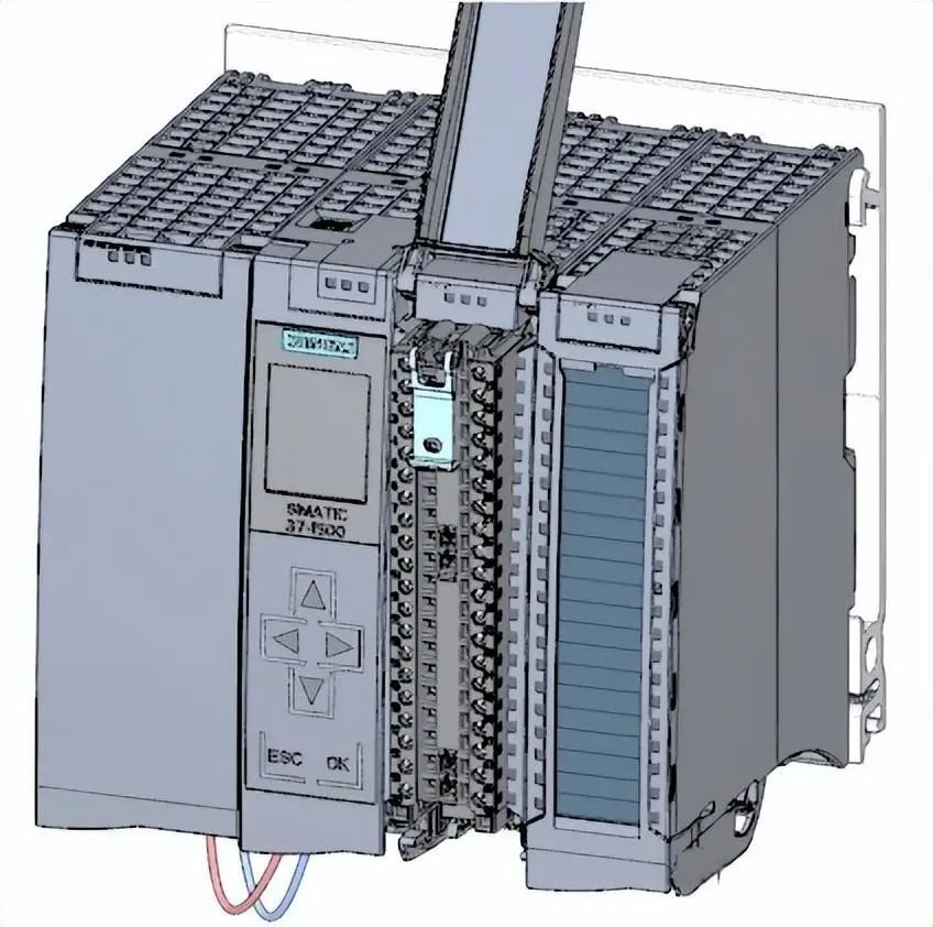 2. Secure the cable with a cable tie.
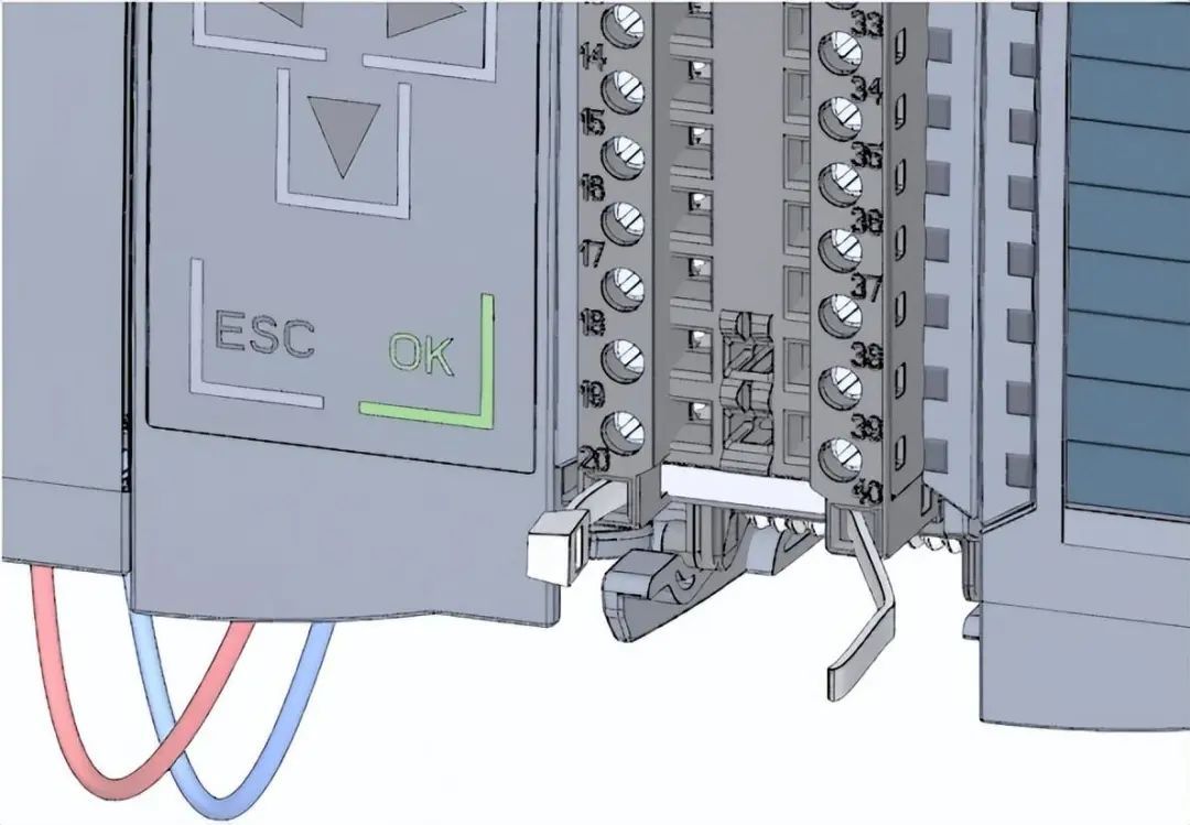 3. Connect the load voltage 24 V DC to terminals 20 (M) and 19 (L+).
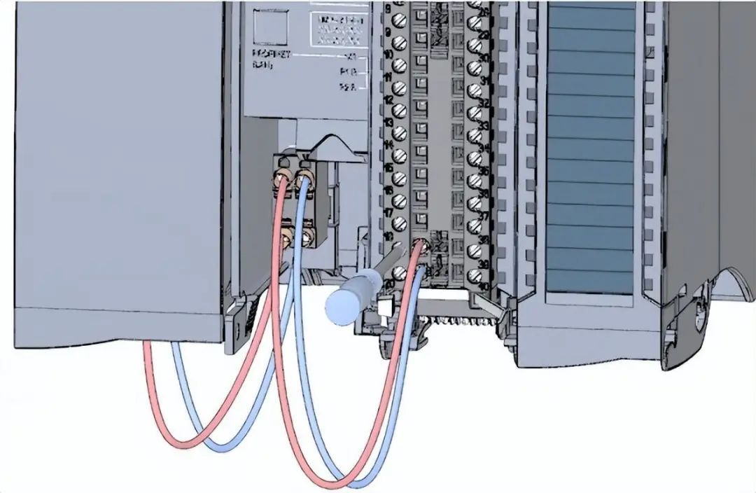 4. Insert a potential circuit bridge between the two bottom terminals.
 Wiring steps for digital output module
1. Insert the front connector into the prewired position.
Wiring steps for digital output module
1. Insert the front connector into the prewired position.
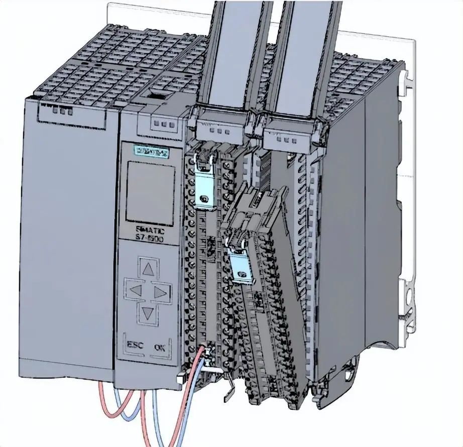 2. Supply DC 24 V power voltage to terminals 20 (M) and 19 (L+) from the digital input module through terminals 40 (M) and 39 (L+) on the digital input module.
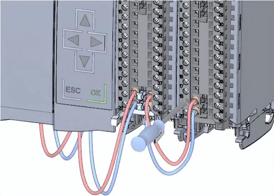 3. Connect four potential circuit bridges.
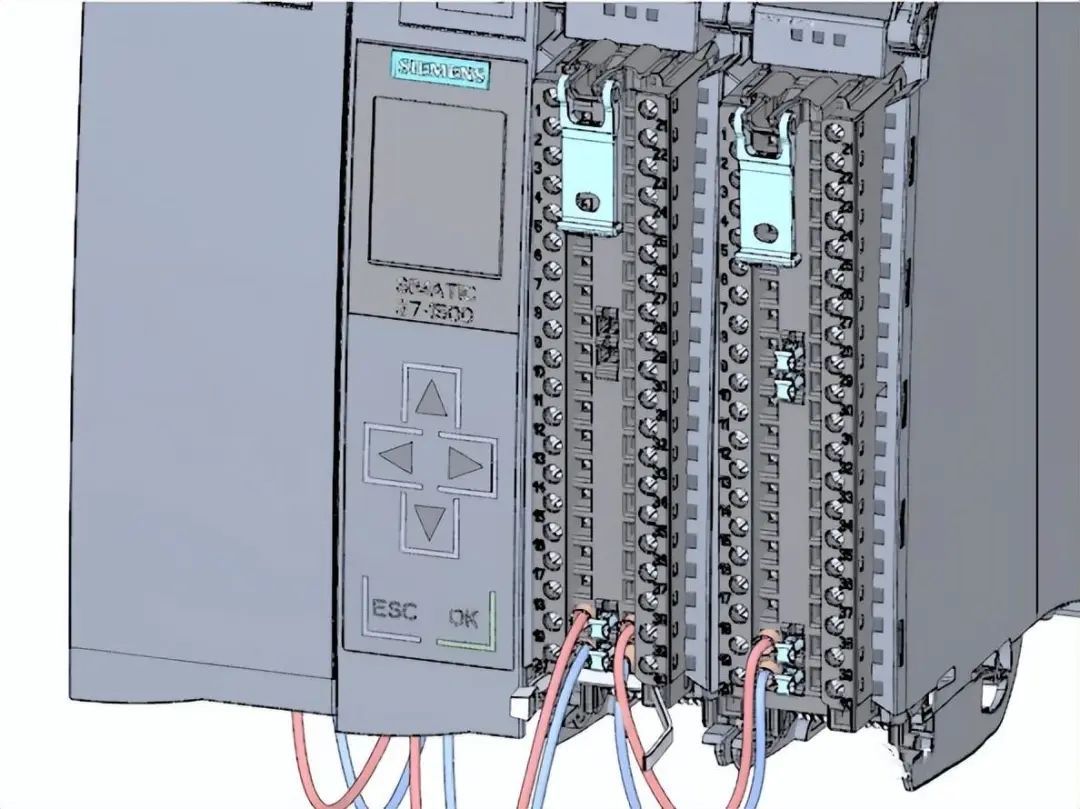 4. Connect terminals 30 and 40, as well as 29 and 39.
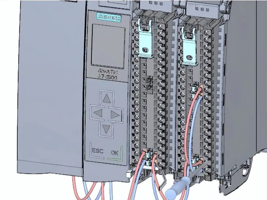 Wiring steps for the front connector
1. Connect each wire according to the wiring diagram on the inside of the terminal front cover and tighten them.
Wiring steps for the front connector
1. Connect each wire according to the wiring diagram on the inside of the terminal front cover and tighten them.
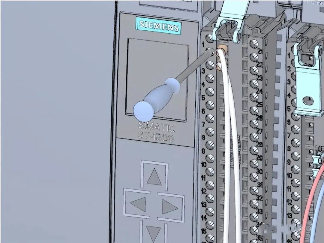 2. To eliminate tension, secure the cables with cable ties and tighten them.
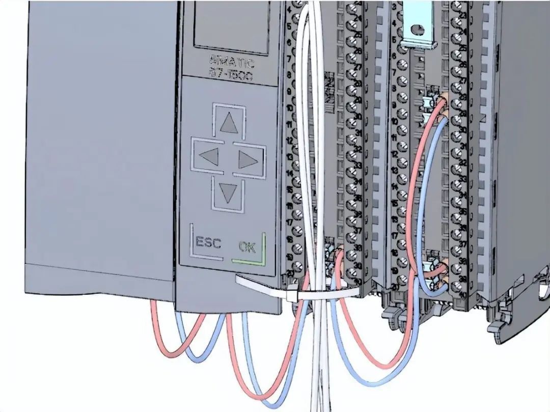 3. Move the front connector from the prewired position to its final position. At this point, the electrical connection between the front connector and the module has been established.
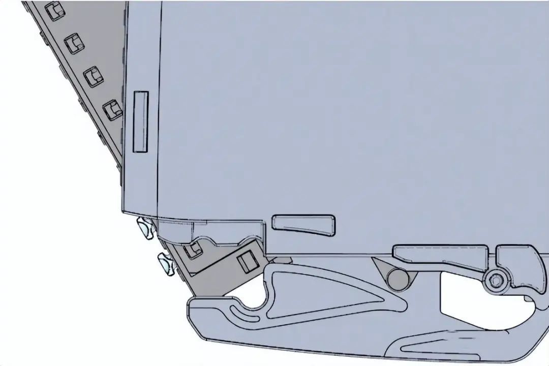 4. Tip: The prewired front connector can be directly inserted, for example, for module replacement.
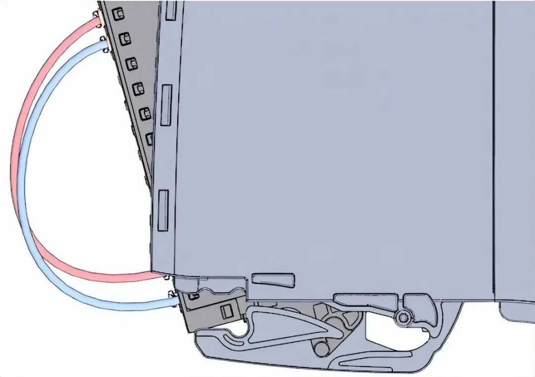 Power-on first CPU startup steps
1. Insert the power connection plug of the load current power supply (PM).
Power-on first CPU startup steps
1. Insert the power connection plug of the load current power supply (PM).
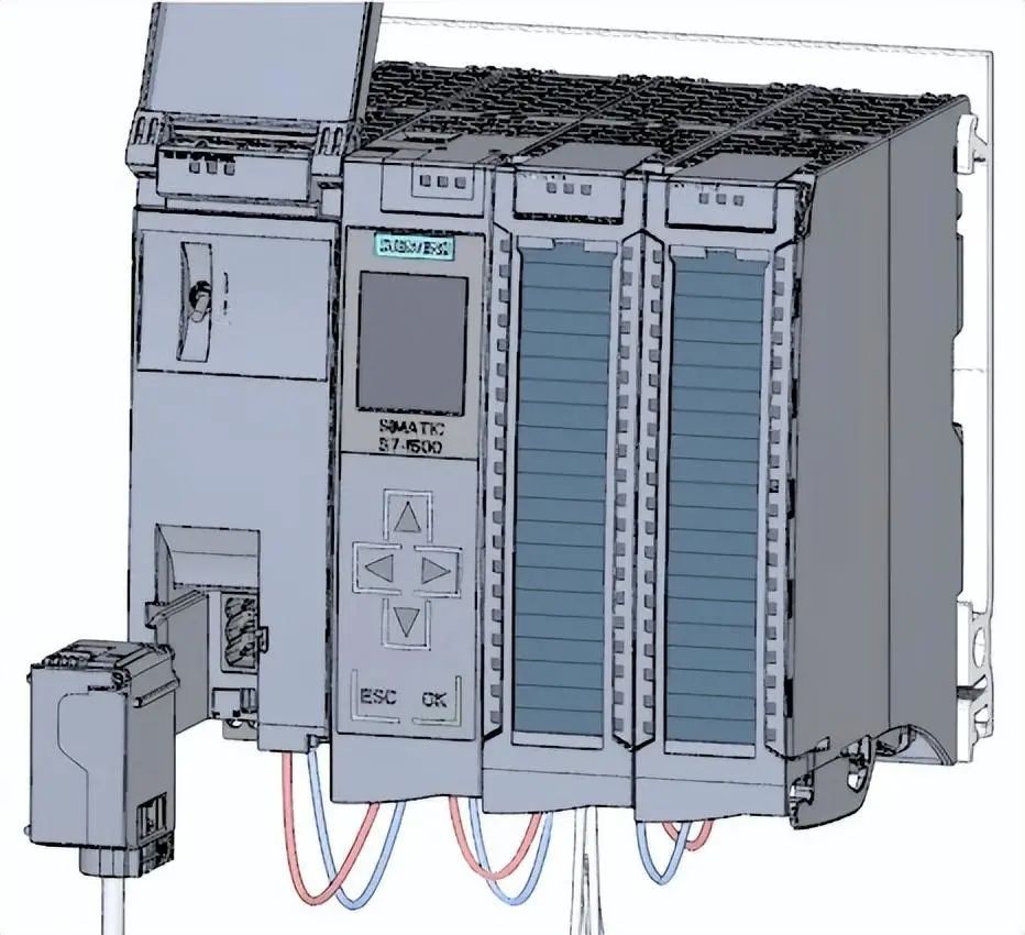 2. Connect the power connection plug to the power source.
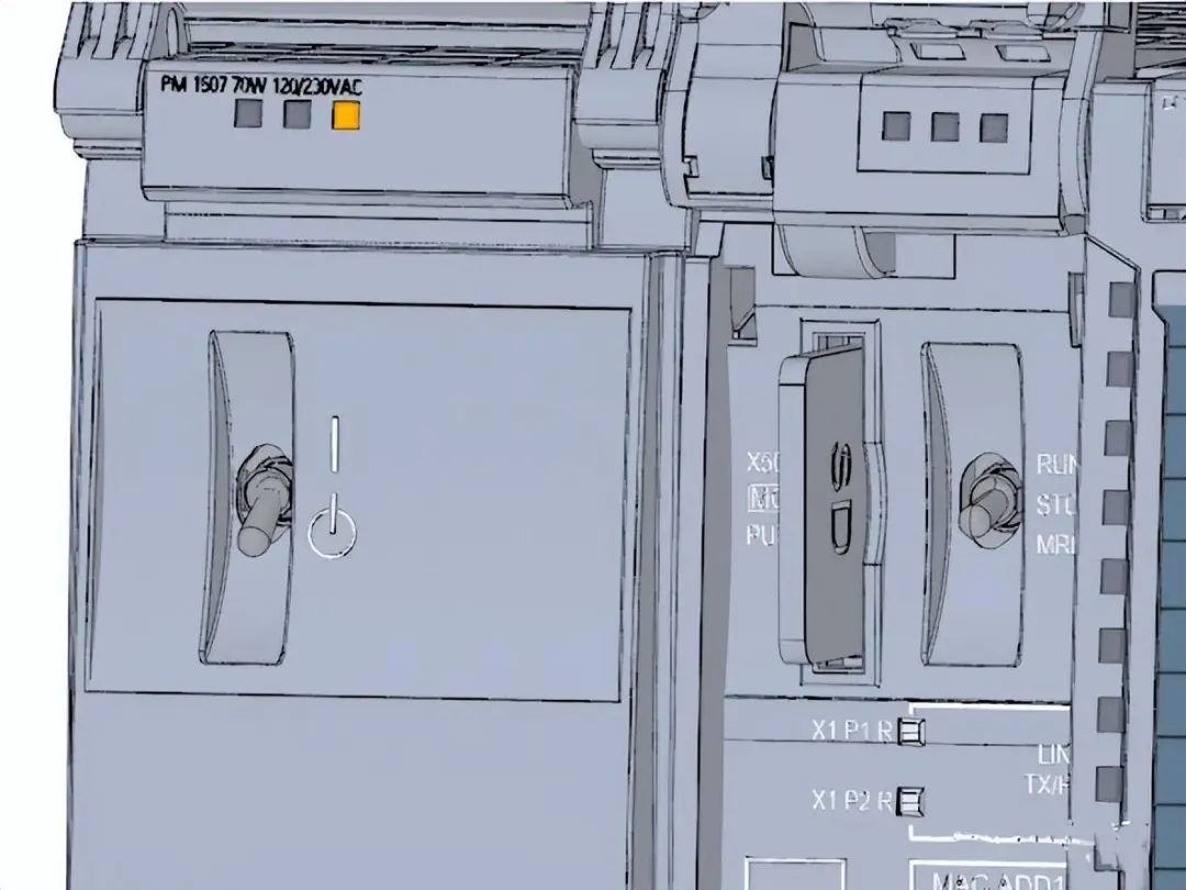
 3. Insert an empty SIMATIC memory card into the CPU.
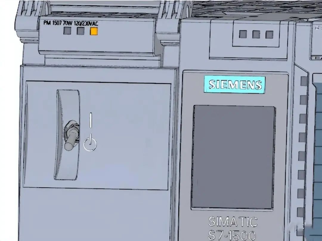
 4. Switch the switch on the load power supply (PM) to the RUN position. The CPU will be started.
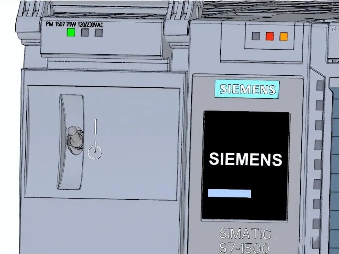 The CPU starts and is in STOP mode. In this step, the IP address and subnet mask of the CPU will be set through the display.
Steps:
1. Navigate to "Settings".
2. Select "Addresses".
3. Select the interface "X1 (IE/PN)".
4. Select the menu item "IP Addresses".
5. Set the IP address to 192.168.0.10.
6. Press the "Right" arrow key on the module.
7. Set the subnet mask to 255.255.255.0.
8. Press the "Down" arrow key on the module to select the menu item "Apply", and then click "OK" to confirm the settings.
PART 06
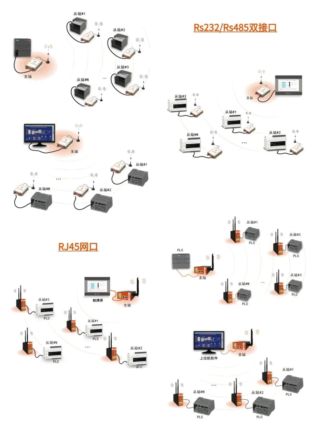
Siemens PLC Wireless Communication
The CPU starts and is in STOP mode. In this step, the IP address and subnet mask of the CPU will be set through the display.
Steps:
1. Navigate to "Settings".
2. Select "Addresses".
3. Select the interface "X1 (IE/PN)".
4. Select the menu item "IP Addresses".
5. Set the IP address to 192.168.0.10.
6. Press the "Right" arrow key on the module.
7. Set the subnet mask to 255.255.255.0.
8. Press the "Down" arrow key on the module to select the menu item "Apply", and then click "OK" to confirm the settings.
PART 06
Siemens PLC Wireless Communication
If you find this helpful, please give a thumbs up


Leave a Reply