

The S7-200 SMART CPU can connect to Siemens HMI devices supporting the PPI protocol through the integrated RS485 port or signal board of the main body, and can also connect to Siemens HMI devices supporting the S7 protocol through the integrated Ethernet port of the main body.When the three physical interfaces of the CPU are simultaneously connected to Siemens HMI devices (including the signal board), the maximum number of connection resources is16..

The connection capacity of the CPU
Smart Panels supports PLCs:
First-generation product SmartLine (without Ethernet interface): S7-200, OMRON CP1 series, Mitsubishi FX series, Modbus RTU;
Note: Only one communication connection can be established, otherwise Smart Panels cannot start the project (white screen).
Second-generation product SmartLine-IE: Serial port: S7-200, OMRON CP1 series, Mitsubishi FX series, Modbus RTU, Delta (DVP-SV/ES2 series);Ethernet: S7-200 (CP243-1), Smart200, LOGO!
Smart Panels can only connect to one device through the serial port and three devices through Ethernet, but the serial port and Ethernet cannot be used simultaneously (compilation fails).
Note: Only one of the serial port and Ethernet port can be used; otherwise, the compilation will fail.
II.
Users need to use WinCC Flexible 2008 SP2 China or later to configure the first-generation product SmartLine. For the second-generation product SmartLine IE, only WinCC Flexible 2008 SP4 China can be used for configuration.
Users can either create a project directly in WinCC Flexible or use a wizard to create one. The following mainly introduces how to create a project directly.
Double-click the SIMATIC WinCC flexible icon on the PC desktop to start WinCC flexible. On the startup screen, select "Create an empty project", as shown in Figure 1. After left-clicking on "Create an empty project", the "Device Selection" interface shown in Figure 2 will open. Select the device to be used in this interface, taking Smart 1000 IE as an example.
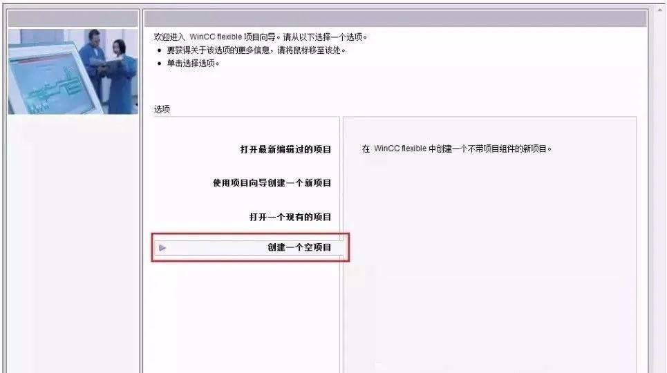
Create a project directly
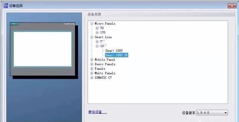 Device selection
III. Configuration
Users can configure the PPI communication between Smart 1000 IE and S7-200 SMART CPU through the following steps.
Step 1:In the main work window of WinCC flexible, expand the tree-like project structure on the left, select "Project" > "Communication" > "Connection", and double-click the "Connection" icon to open the "Connection Settings" property window.
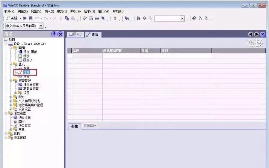
Open the connection window
Step 2:In the "Connections" window, double-click the blank table below the name, or right-click and select "Add Connection" from the shortcut menu to add a connection to the CPU.
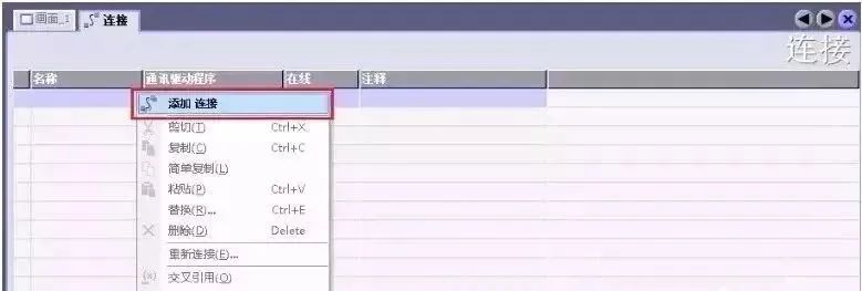
Add connection
Step 3:After adding a connection, users can modify the default connection name "Connection_x" according to project requirements, and select "Communication Driver" and whether it is online. Since the connected device is an S7-200 SMART CPU, select "SIMATIC S7 200 SMART" as the communication driver from the dropdown menu below "Communication Driver", and activate the online connection.
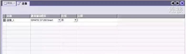
Configure connection
Step 4:Set connection parameters. First, select the interface of Smart 1000 IE as "IF1 B", which is the RS422/485 physical interface of the touch screen. After selecting this interface, the parameter setting window for this interface will automatically display below it. Set the communication baud rate of the touch screen to 187500 and the station address to 1.Next, in the "Network" window, select "PPI" as the communication protocol for both communication parties.
Finally, set the CPU's station address in the "PLC Device" window. Here, set the CPU's station address to 2, as shown in the figure.
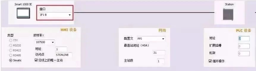
Connection parameter settings
Note: The address of the CPU must be different from that of the HMI device, and the two cannot be duplicate.
Step 5:Set the baud rate and station address of the S7-200 SMART CPU. Select "System Block" in the project tree of the STEP 7 Micro/WIN SMART software, and press "Enter" to open the "System Block" window as shown in Figure 7. The station address and baud rate set for the CPU's RS485 port must be consistent with the configuration in Figure 6. The CPU's station address is 2, and the communication baud rate is 187.5 kbps.
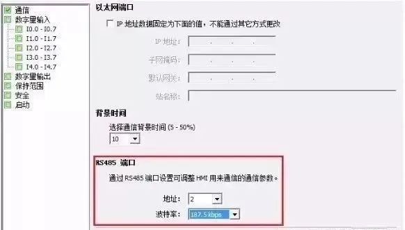
S7-200 SMART Communication Port Settings
By now, the PPI communication between Smart 1000 IE and S7-200 SMART CPU has been configured.
IV. Startup
When powering on the Smart 1000 IE device, the screen will briefly display the startup screen, as shown in Figure 8. The three buttons in the figure represent the following.
Transfer: The HMI device is set to "Transfer" mode.
Start: Starts the project loaded on the HMI device.
Control Panel: Clicking this button enters the control panel of the HMI device, where users can select the transmission mode, add passwords, etc.
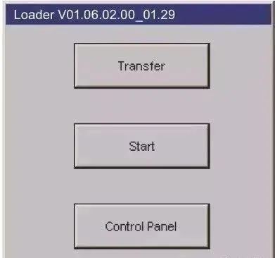
Startup Screen V. Download
To download the configured project to the Smart 1000 IE device, first ensure that the communication port of the HMI device is active. This can be set through the "Control Panel" > "Transfer" of the HMI device, as shown in Figure 9. If you choose to download the project via serial port, you must first check the "Enable Channel" next to "Serial".
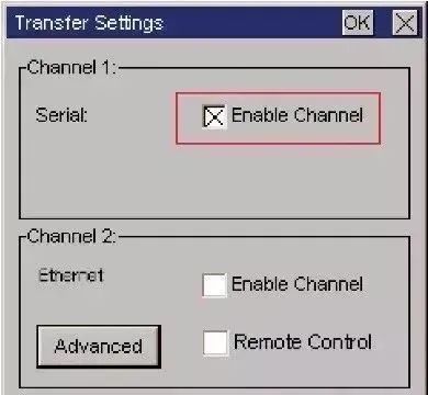
Enable communication port
Next, to download the project using the original Siemens PPI programming cable, both the RS-232/PPI cable (order number 6ES7 901-3CB30-0XA0) and the USB/PPI cable (order number 6ES7 901-3DB30-0XA0) can be used. When using the USB/PPI cable, it is required that its E-STAND version is 05 or higher.
Then, in the menu bar of WinCC flexible software, select "Project" > "Transfer" > "Transmit", as shown in Figure 10. Clicking "Transmit" will open the "Select Device for Transfer" window, as shown in the figure. In the "Select Device for Transfer" window, users can choose the transmission mode as "Serial" or "Serial Port (via USB-PPI Cable)", and select the latter for transmission.
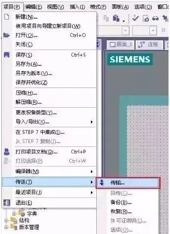
Open Transfer Settings
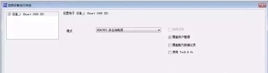
Transfer Settings
After powering off and then powering on the Smart 1000 IE device, the HMI device will display the startup screen. Click the Transfer button to place the HMI device in "Transmit" mode.
Then, in WinCC flexible software, select "Project" > "Transfer" > "Transmit", and click the "Transmit" button in Figure 11. When the transmission status in the HMI device displays "Transmission Complete", the project has been successfully transferred to the HMI device via serial port mode.
Update in 2026: Adaptation Instructions for Second-Generation Smart Line with S7-200 SMART V2.8
The S7-200 SMART CPU firmware has been updated to version V2.8, and the driver for the second-generation Smart Line (Smart Line IE V4) touch screen has also been upgraded accordingly. Actual measurement verification - under the same configuration, the PPI communication response time of the V2.8+V4 combination is about 15% shorter than that of the previous generation.
Note:
- Please back up the PLC program and HMI project before upgrading the firmware.
- The V2.8 version has stricter verification for RS485 port parameters - settings such as baud rate, data bits, stop bits, and parity bits must be consistent between the PLC and HMI ends, otherwise the connection will be actively rejected.
- If Modbus RTU is used for communication with third-party devices, it is recommended to split the RS485 port of the PLC through a 485 hub to avoid conflicts caused by shared ports between PPI and Modbus.
For project solution consultation, please contact the Modbus technical team.


Leave a Reply