
In this case, the communication between the PLC and the serial device server utilizes the "transparent transmission mode", and the communication between the PLC and the platform employs the MODBUS-RTU protocol.
The S7-200 supports the MODBUS-RTU communication protocol through the following two methods:
(1): The communication port 0 (port0) on the S7-200 CPU supports the Modbus RTU slave mode through the instruction library.
(2): Both communication ports 0 and 1 (port0 and port1) on the S7-200 CPU support the Modbus RTU master mode through the instruction library.
(Note: The instruction library can be downloaded from the relevant website provided by Siemens.)
In this case, the first method is used, with the S7-200 acting as a slave for communication with the Modbus IoT platform.
I. Product Selection:
1. PLC: S7-200CN
2. ZLAN serial device server ZLAN5143
II. Setting PLC Communication Information
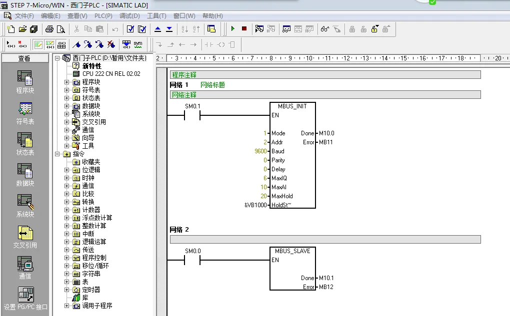
The example program for S7-200 communication is shown in the figure below: (There is a routine download on this page).
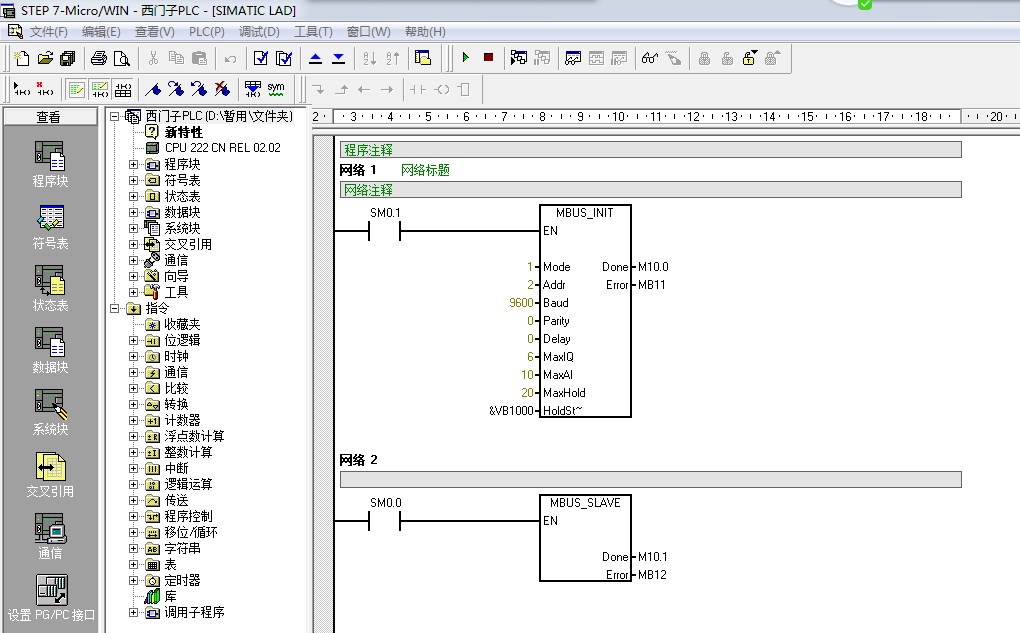
Mode: Start/Stop Modbus, 1=on; 0=off
Addr: Modbus Slave Address, value range 1-247
Baud: Baud Rate, optional values 1200, 2400, 4800, 9600, 19200, 38400, 57600, 115200
Parity: Parity Bit, 0=No Parity; 1=Odd Parity; 2=Even Parity
Delay: Delay, additional delay between characters, default value is 0
MaxIQ: Maximum IO Points, generally settable to 128.
MaxAI: Maximum AI Channels, depends on the specific situation of the PLC, generally settable to 16 or 32.
Maxhold: Maximum Holding Register Area.
Holdstart: Holding Register Starting Area, specified by &VBx.
Done (in Network 1): Initialization Completion Flag, set to 1 after successful initialization.
Error (in Network 1): Initialization Error Code, 0 indicates no error
Done (in Network 2): Set to 1 during communication, and set to 0 when there is no Modbus communication.
Error (in Network 2): Communication error code, 0 indicates no error.
Holdstart and MaxHold specify the area of the hold register, and the range of the hold register area must not conflict with the range of the program storage area, otherwise communication cannot be established.
The value of the hold register start area specified in the above figure is 1000, but it is not mandatory to specify 1000. As long as the program storage area is set properly, communication can be successfully established. The setting of the program storage area is shown in the following figure:
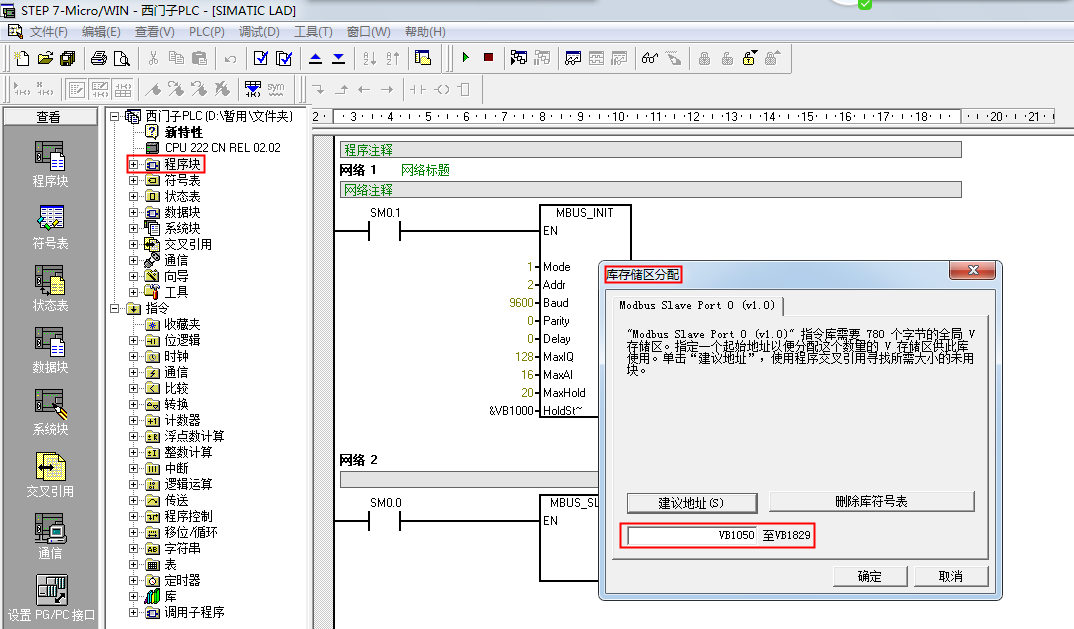
In the program block, the program storage area is allocated from 1050 to 1829. Since the area specified by Holdstart and Maxhold is from 1000 to 1040 (Maxhold specifies the number of VWs, so it needs to be multiplied by 2 for VB), the program storage area is allocated from VB1050 to VB1829.
III. Writing Control Programs
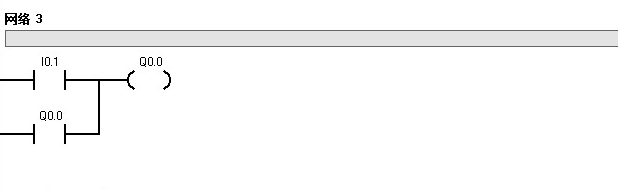
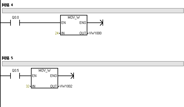
After writing the communication program and allocating the storage area, it can be used as a slave station and master station for communication. To better demonstrate the effect, some additional control programs have been written, and the control program is shown in the following figure:
IV: Configure Serial Server
Configuration of ZLAN5143 Serial Server
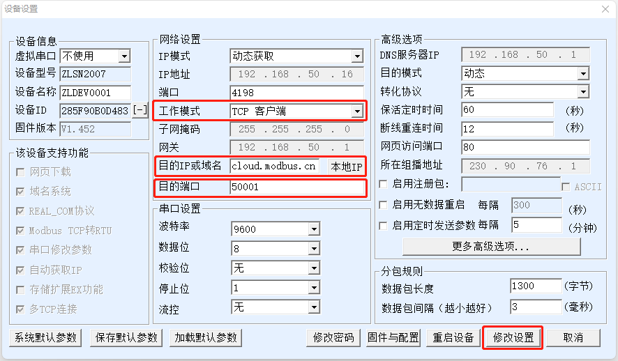
Open the ZLAN Virtual Serial & Device Manager configuration software, connect to the Ethernet port or serial port, and only need to fill in the following sections:
Step 1:
- Working Mode: TCP Client
- Destination IP or Domain: cloud.modbus.cn
- 47.104.68.157 (Alternate)
- www.wulianwang.net.cn (Alternate)
- Destination Port: 50001
- Modify Configuration (Save)
As shown below:
Step 2:
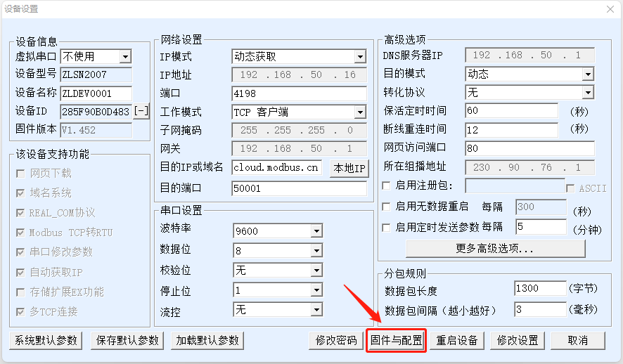
Click "Firmware and Configuration"
Create a new empty "web" folder on the C drive, select this folder, and then click "Register Package"
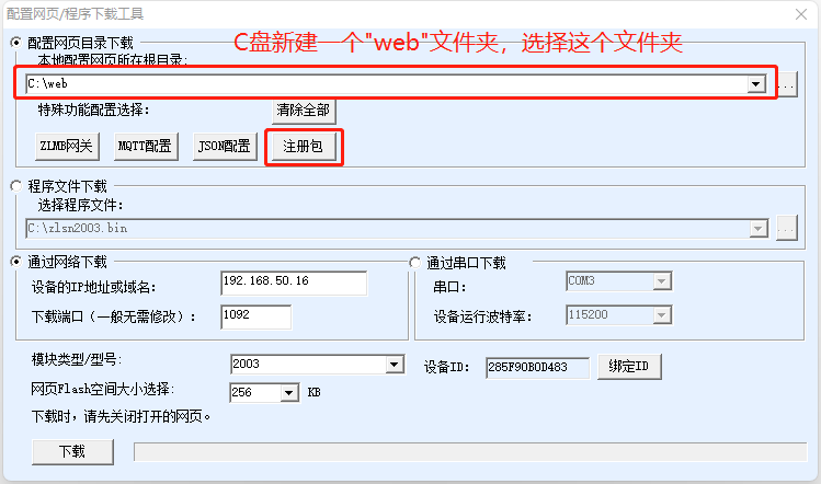
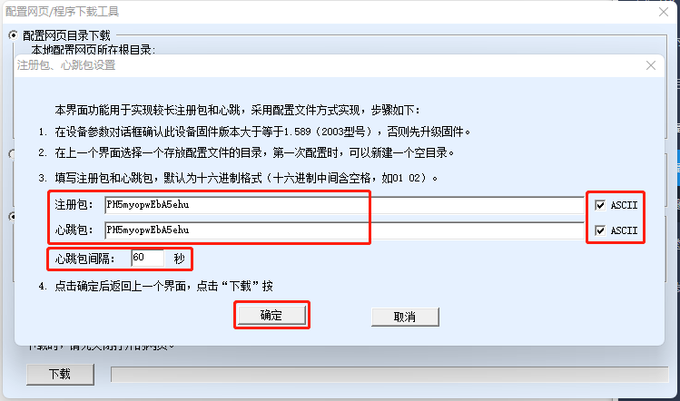
Check both the "Register Package" and "Heartbeat Package" in "ASCII" format, then fill in the device number generated by the cloud platform, set the heartbeat interval to "60" seconds, and click "OK" to save.
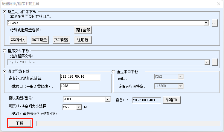
After the page jumps, click "Download".
V. Configure Modbus IoT Platform Read and Write Commands
Preparations on the MODBUS IoT Platform
In practice, we usually use a serial server as a transparent gateway to forward messages between Modbus sub-devices and the cloud platform. Here, we use the TCP client mode of the serial server. The preparations only require the following steps:
- Create a project (Project Management → New Project).
- Create a device (Device Management → Device Information → New Device)
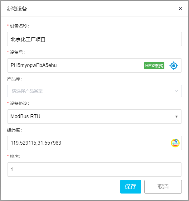
- Fill in the device name, generate randomly or manually enter the device number, select ModBus RTU in the device protocol, locate the device's latitude and longitude, and save. (Save the device number for later use)
For specific steps, please refer to:Introduction to Modbus, which can usually be completed in a few minutes.
On the Modbus IoT Platform, click Device Management, select a project, and choose "Add Slave" in the device list to add a slave device node:
The Modbus addresses corresponding to each area of the PLC are as follows:
·00001-09999: Digital output (coil, readable and writable)
·10001-19999: Digital input (contact, readable only)
·30001-39999: Input data registers (usually analog inputs, read-only)
·40001-49999: Data holding registers (readable and writable)
The addresses corresponding to the values written into the registers in the above program are 40001 and 40002, which correspond to the 03 function code (readable and writable) registers in the platform as 1 and 2
The data format can be filled in as a 16-bit unsigned or signed number according to the actual situation.



11111111111111111111111111111111
漂亮
很好
谢谢提供资源
学习了,感觉自己的水平微不足道,努力学习啊··
学习一下 下步用用
漂亮
非常感谢作者的奉现,让我受益非浅。
kan kan an li shifou you