
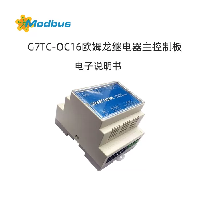
Function Introduction
A centralized control module that supports bus wireless wired dry contact control and a separate design from relays, significantly reducing maintenance costs. Group address function, batch execution of multiple scene control with one instruction, easily achieving preset scenarios such as single point, multi-point, area, and group control.
Recommended to use
Widely applicable to users with centralized control needs such as homes, office buildings, hotels, hospitals, schools, stations, sports centers, museums, exhibition centers, factories, agriculture, shopping malls, etc.
Product Features
Supports RS485, wireless, wired, and dry contact control modes
Outstanding response speed, anti-interference ability, and stability.
can quickly interface with bus panels with active transmission function and a baud rate of 9600.
supports feedback, receiving custom control instructions while also providing feedback on standard status protocols, compatible with both third-party panels and third-party bus control systems.
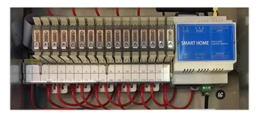
The centralized control main control board and relay are designed in a separated manner to maximize the reliable operation of the equipment and significantly reduce maintenance costs in the later stage. (To be used with relay module)
group address function, batch execution of scene control with one instruction, easy to achieve scene presets such as single point, multi-point, area, group control, etc., reducing bus occupation. For example, one instruction can put hundreds of circuit lights on a building in different scene states.
Paired with multiple intelligent accessories to achieve personalized scene control.
Remote control, ready to control at any time (needs to be used in conjunction with an intelligent control system).
Fearless of network disconnection, able to control even in the absence of network.
Supports running off the host and sending custom scene commands.
Supports access to third-party bus control systems and enables bidirectional communication.
Supports full customization of input control protocol and output control protocol.
Supports delayed closing and delayed opening between 1-255s.
Supports button locking to prevent accidental touch.
Support timed power on/off (to be used in conjunction with an intelligent control system).
Support voice control (requires the use of an intelligent control system or an offline voice control module).
The power on state configuration protocol allows customization of the power on or off state for any number of output channels.
Custom staircase protocol allows for customization of the delay and opening/closing sequence between relays.
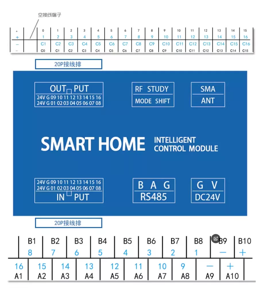
Interface Diagram
How to use RS485 protocol
1. Address modification method
After the device is powered on, it will automatically provide a 5-byte address feedback (for example, if the address is 1A 13 24 56 91, use XX XX XX XX to replace it)
Send XX XX XX XX XX (old address) F8 E7 D6 (fixed) XX XX XX XX XX XX XX (new address)
Example: 1A 13 24 56 91 F8 E7 D6 2A 33 57 26 81 Change the old address 1A 13 24 56 91 to the new address 2A 33 57 26 81
2. Group control address
Address wildcard: FF
Broadcast address: FF FF FF FF FF
FF can be located at any position of the five byte address in XX XX XX XX XX XX.
Modify address branching to achieve group control and scenario control through the configuration of addresses and wildcard characters.
Example:
- Send XX XX XX FF: a module that can control 254 addresses of XX XX XX XX 00-XX XX XX XX XX FE
- • Send XX FF FF XX XX: a module that can control a total of 254 * 254 addresses for XX 00 XX XX XX FE XX XX XX XX XX
- • Send FF FF XX FF XX: A module that can control a total of 254 * 254 * 254 addresses for 00 00 XX 00 XX-FE XX FE XX FE XX
- • Send FF FF FF XX: A module that can control a total of 254 * 254 * 254 * 254 addresses for 00 00 00 XX-FE FE FE XX
- • Send FF FF FF FF: can control all modules
3. Single control command
XX XX XX XX XX (address) 00 (fixed) 00 (number of channels) 02 (function) 0F
Number of channels: 00 01 02 03 04 05 06 07 08 09 0A 0B 0C 0D 0E 0F corresponds to the functions of the 1st to 16th channels
Function: 02 on/off, 01 on, 00 off, 03 jog
Example: XX XX XX XX XX 00 02 0F 1st channel switch flip
4, multiple overall operation instructions
- • 01-08 channels fully open/close:XX XX XX XX XX XX XX XX (address) 01 (01 fully open/02 fully closed) 77 88 0F
- • 09-16 channels fully open/fully closed Close:XX XX XX XX (Address) 10 (10 fully open/20 fully closed) 77 88 0F
- • 01-16 fully open/closed:XX XX XX XX XX (Address) 30 (30 fully open/40 fully closed) 77 88 0F
Example: XX XX XX XX 10 77 88 0F Circuit 9-16 switch fully open
5. Composite operation command (1 command controls 16 relays)
XX XX XX XX XX XX (address) CA (fixed) 00 (circuit) 02 (function) 01 (circuit) 02 (function) .... 0F (number of channels) 02 (function) OFNumber of channels: 00 01 02 03 04 05 06 07 08 09 0A 0B 0C 0D 0E 0F corresponds to channels 1-16
Function: 02 on/off, 01 on/off, 00 off, 03 jog, 04 maintain original state
Example: XX XX XX XX XX CA 00 01 01 01 02 01 03 00 04 00 05 00 06 02 07 02 08 02 09 03 0A 03 03 0C 04 0D 04 0E 04 0F 04 0F Turn on the first path, turn on the second path, turn on the third path, turn off the fourth path, turn off the fifth path, turn off the sixth path, flip the seventh path, flip the eighth path, flip the ninth path, jog the tenth path, jog the eleventh path, jog the twelfth path, keep the thirteenth path in its original state, keep the fourteenth path in its original state, keep the fifteenth path in its original state, and keep the sixteenth path in its original state.
6. Status query instruction
SendXX XX XX XX XX (Address) 86 86 86 0F
FeedbackXX XX XX XX XX XX XX (Address) 00 00 00 01 00 01 01 01 01 00 01 0F (00 off 01 on) Protocol instruction
ExampleSend XX XX XX XX 86 86 0F
Feedback: XX XX XX XX 00 00 01 01 00 01 01 01 01 01 00 01 00 01 01 0F indicates that the status of channels 1-16 is off, off, on, off, on, off, on, off, on, off, on
7. Stair protocol instruction
XX XX XX XX XX (address) CB (function) 00 03 (time interval for sequentially opening) 00 04 (time to keep all open) 00 05 (time interval for sequentially closing) 0F
- • Time interval for sequentially opening, range 00 00 00 FF FF, time unit 0.1 second
- • The time to keep all open, ranging from 00 to FF FF, with a time unit of 0.1 seconds
- • Time interval for sequentially closing, range 00 00 FF FF, time unit 0.1 second
Function: CB 1-16 channels are turned on in the forward direction; CC 1-16 channels are opened in reverse order; CD 1-8 channels are sequentially turned on in the forward direction; CE 1-8 switches are turned on in reverse order; CF 9-16 channels are sequentially opened in the forward direction; CO 9-16 routes are sequentially opened in reverse;
Example: XX XX XX XX CB 00 03 00 04 00 05 0F The switch and backlight are turned on in a forward direction, with a time interval of 0.3 seconds between turns; Keep all open for 0.4 seconds; The time interval for sequentially closing is 0.5 seconds
8. Custom staircase command
XX XX XX XX XX XX XX (address) D3 (fixed) 00 01 (delay time interval) 01 (01 on/00 off/02 flip) 01 (01 forward/11 reverse) 01 (01 front 8 channels/11 rear 8 channels/02 overall) 0F
- • Delay time interval, range 00 00-FF FF, time unit is 0.1 seconds
Example: XX XX XX D3 00 05 01 11 0F Backlight is turned on sequentially in the forward direction, with a delay time interval of 0.5 seconds
9. Corresponding configuration buttons and outputs Relationship (Input Control Output)
- • Single Switch Single Output:XX XX XX XX XX (Address) BB 00 (Fixed) 00 (Number of Channels) F1 (F1 Long Press/F2 Single Click/F3 Double Click) CA (Fixed) 02 (Number of Channels) 02 (Output Status 00 Off/01 On/02 Switch/03 Jogging) 0FExample: XX XX XX XX XX BB 00 03 F1 CA 04 02 0F (Press and hold button 4 to operate output switch 5)
- • Single switch multiple output:XX XX XX XX XX (Address) BB 00 (Fixed) 00 (Number of Channels) F1 (F1 Long Press/F2) Click/F3 Double Click) CA (Fixed) 00 (Output 1) 02 (On/Off) 01 (Output 2) 01 (Only On) 02 (Output 3) 03 (Jogging) 0FExample: XX XX XX XX BB 00 F1 CA 00 02 02 02 02 0F (Press button 1 to switch on/off with output switches 1, 2, and 3)
- • Delete configuration:XX XX XX XX XX (Address) BB 00 (Fixed) 00 (Number of Channels) F1/F2/F3 EE 0FExample: XX XX XX XX BB 00 02 F1 EE 0F (configuration to delete button 3 F1)
Number of channels: 00 01 02 03 05 06 08 09 0A 0B 0C 0D 0E 0F corresponds to buttons 1-16
Output: 00 01 02 03 05 06 08 09 0A 0B 0C 0E 0F corresponds to outputs 1-16
10. Button sends custom bus data command
- • Configuration:XX XX XX XX XX (address) BB 00 (fixed) 00 (number of channels) E1 (E1 relay on/E2 relay off/E3 click/E4 double-click/E5 long press) 01 (storage) YY YY YY YY YY YY YY YY YY YY YY YY YY YY YY YY YY YY (custom bus data hex) 0FThis custom protocol can be used to control bus controlled devices. When the key input status is on/off, it sends custom bus data YY YY YY YY YY YY YY YY YY YY YY YY YY YY YY
- number of channels: 00 01 02 03 04 05 06 08 09 0A 0B 0C 0D 0E 0F corresponding to keys 1-16
- Storage: 01-06 represents the first to sixth storage, supporting the storage of six instructions
- Example 1: XX XX XX XX BB 00 02 E3 01 55 12 35 03 01 FC 4A 0F Storage 1: When button 3 is clicked, send curtain bus data 12 35 03 01 FC 4A 0F, open curtain
- Example 2: XX XX XX XX BB 00 02 E4 55 12 35 03 01 FC 4A 0F Storage 2: When button 3 is double clicked, send curtain bus data 12 35 03 01 FC 4A 0F, open curtain
- • Configure bus data transmission Interval Time:XX XX XX XX XX (Address) BB D1 (Fixed) 00 08 (Interval) 0FSet the bus data transmission interval time based on the performance of the controlled product, ranging from 00 to FF FF, with a unit of 50 milliseconds and an interval time of 8 * 50=400 milliseconds
- Example: XX XX XX XX XX BB D1 00 02 0F The interval time for sending each bus data is 100 milliseconds
- • Delete configuration:XX XX XX XX XX (Address) BB 00 (Fixed) 00 (Number of Channels) E1/E2/E3/E4/E5 EE 0F
- Number of Channels: 00 01 02 03 04 05 Corresponding to Keys 1-6
- Example: XX XX XX XX XX BB 00 03 E1 EE 0F Delete configuration of Key 4
11. Delete all input configuration data
XX XX XX (Address) BB EE EE 0FDelete all data from 16 channels
12. Lock button command
- • Lock button, fully open switch:XX XX XX XX XX XX (address) EC 00 FF FF 0F
- • Lock button, switch fully closed:XX XX XX XX XX XX (address) EC 00 00 00F
13. Unlock button command
- • Unlock button, switch fully open:XX XX XX XX XX XX (address) EC 01 FF 0F
- • Unlock button, switch fully closed:XX XX XX XX XX (address) EC 01 00 00F
14. Switch delay configuration (this mode requires configuring the button as jog mode)
XX XX XX XX XX XX (address) 9F (fixed) 01 (road) Number: 01 (time) 0F
Number of channels: 00-0F correspond to channels 1-16 respectively
Time: 01-FF corresponds to 1-255 seconds
Example: XX XX XX XX 9F 08 06 0F 9th channel delayed by 6 seconds
15. Power on initial state configuration instruction
XX XX XX XX XX XX (address) EA (fixed) 00 (number of channels) 01 (01 on/00 off) 01 (number of channels) 00 (01 on/00 off) 02 (01 on/00 off) 01 (01 on/00 off) 01 (01 on/00 off) 01 (01 on/00 off) 0F
BI_163] Number of channelsNumber of routes: 00-0F correspond to channels 1-16
, with every 2 bytes forming 1 group. Set the initial power on state, 01 on/00 off
The default initial power on state is off
Example: When XX XX XX EA 00 01 00 02 01 0A 01 0B 00 0C 00 0F is initially powered on, the first channel is turned on, the second channel is turned off, the third channel is turned on, the 11th channel is turned on, the 12th channel is turned off, and the 13th channel is turned off.
16. Feedback Mode Configuration Protocol
XX XX XX XX XX (Address) BB D2 00 (Fixed) 00 (00 opens standard active feedback/01 opens custom active feedback/03 closes active feedback) 0FFeedback is divided into standard feedback and custom feedback
- • Standard active feedback: FeedbackXX XX XX XX XX (Address) 16 byte switch status (0 off/1 on) 0F
- • Custom active feedback: Feedback on custom bus data configured in input and send custom bus data instructions
Example: XX XX XX BB D2 00 00 OF opens Standard Active Feedback
Send XX XX XX XX 86 86 0F
Feedback XX XX XX XX XX 00 00 01 01 00 01 01 01 00 01 0F Indicates that the status of channels 1-16 is off, off, on, off, switch off, switch on


Leave a Reply