
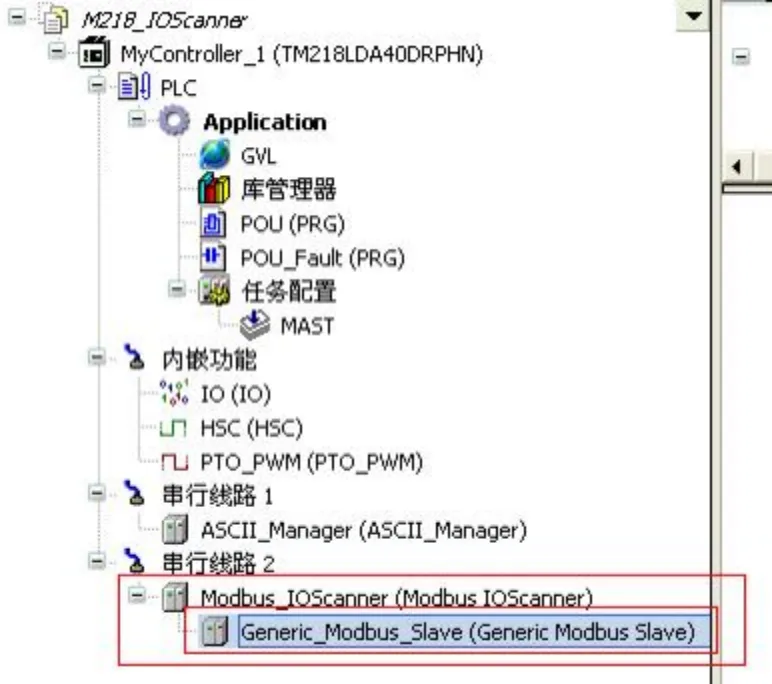
1. First, change the serial line to Modbus_IOScanner (Modbus IOScanner) and set the frequency converter accordingly.
1) Set the communication mode to Modbus given.
2) Set the slave address (1...247) to match the setting in the software.
3) Set the communication rate to 19.2K, which should match the setting in the software.
4) Set the communication format to 8E1, with 8 data bits, even parity, and 1 stop bit.
Note: After setting, power off and then power on the frequency converter for the parameter settings to take effect.
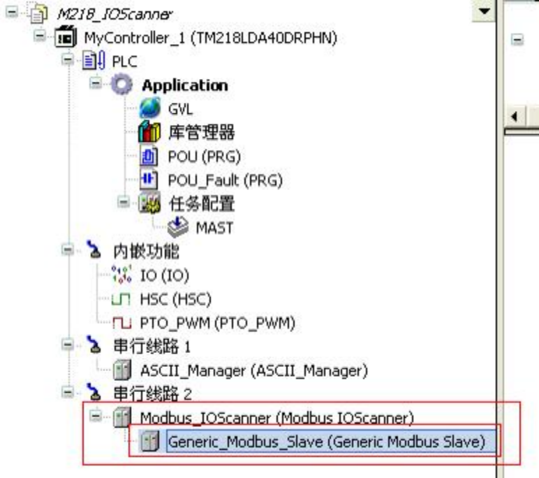
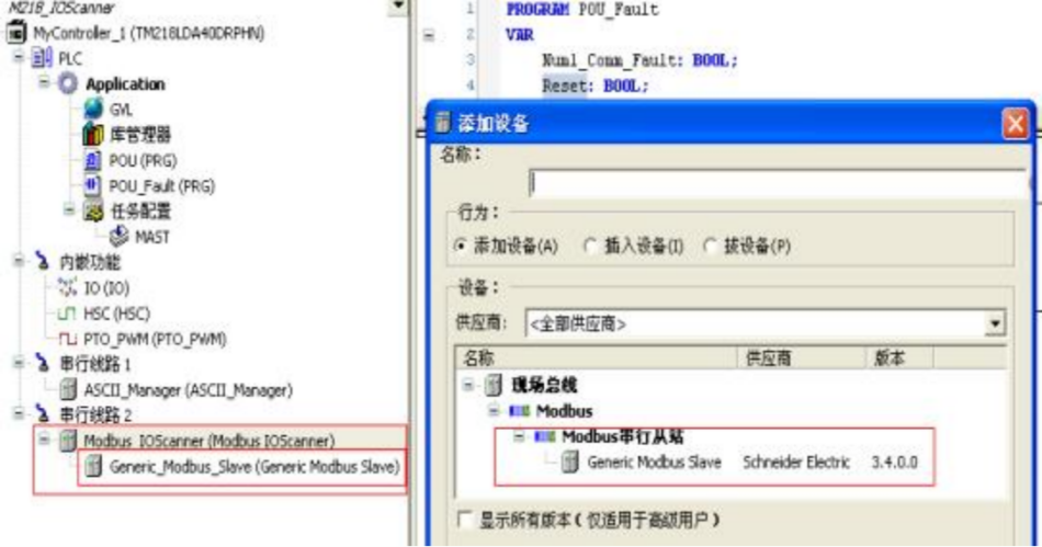
2. Right-click on Modbus_IOScanner (Modbus IOScanner), click Add Device, and add a slave device.
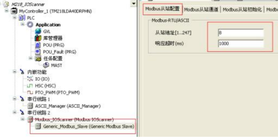
3. After adding the slave device, add the slave address in the Modbus slave configuration.
4. Add channels in the Modbus slave channel as shown below.
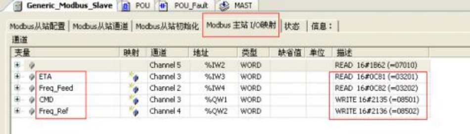
(16#0C81=3201, frequency converter ATV71 ETA status word)
(16#0C82=3202, frequency converter ATV71 Freq_Feed frequency feedback)
(16#2135=8501, frequency converter ATV71 CMD control word)
(16#2136=8502, frequency reference set for frequency converter ATV71 Freq_Ref)
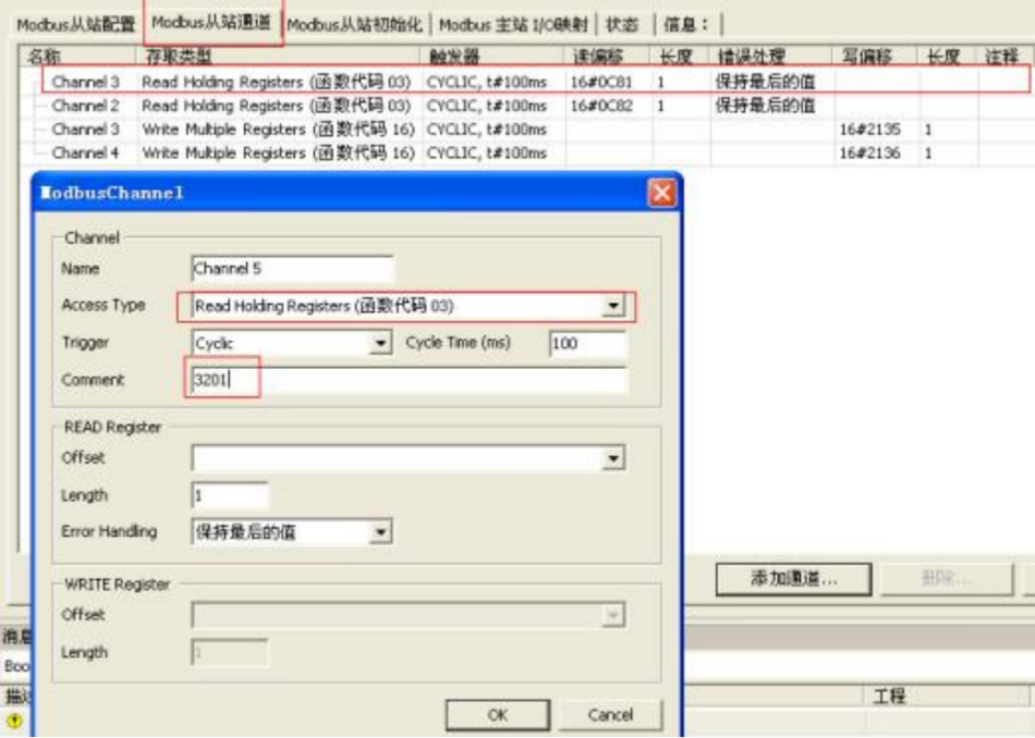
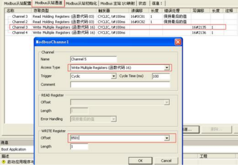
5. Add variable names in the Modbus master I/O mapping, ensuring they correspond to the descriptions
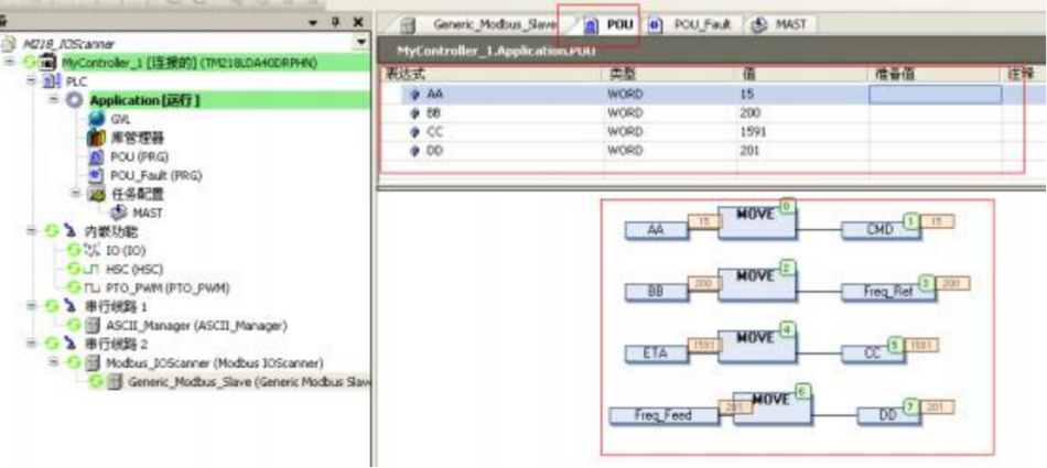
6. Write a program in POU
to manually set the control word CMD to 6 (16#0006), indicating the frequency converter is ready
manually set the control word CMD to 7 (16#0007), indicating the frequency converter is stopped,
manually set the control word CMD to 15 (16#000F), indicating the frequency converter is rotating forward
manually set the control word CMD to 2063 (16#080F), indicating the frequency converter is rotating in reverse
set the frequency reference Freq_Ref, and the frequency of the frequency converter's rotation is HZ=Freq_Ref/10
7. When the Modbus slave device is powered on and off, a "triangle" symbol will appear before the slave device in the PLC. In this case, the human-machine interface can also be used to clearly see which Modbus slave the PLC has not read!
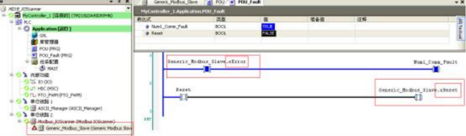
8. At this time, the PLC needs to send a reset signal to itself to ensure normal communication. The reset procedure is shown in the figure
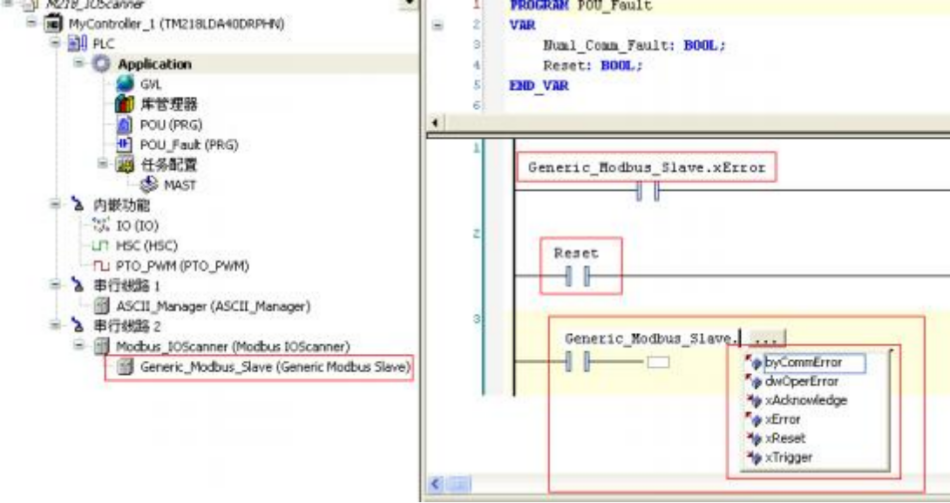
9. Reset steps and effects after resetting
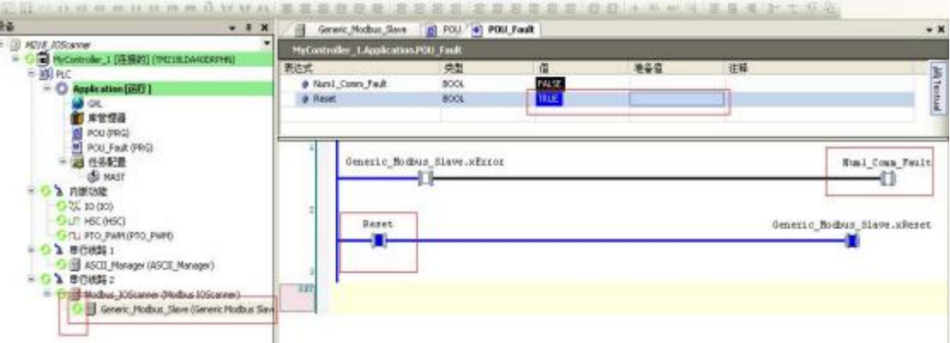
Note: This is only a reset of the PLC to itself. If the Modbus slave device itself has a fault, or if a slave device reports a Modbus fault, it cannot be reset!


555
555′”
555
555
555