
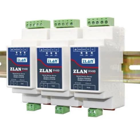
Overview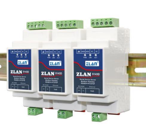 Figure 1 ZLAN5143D White Model
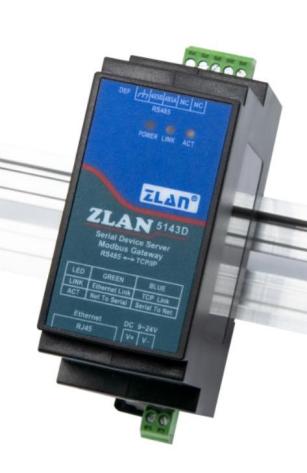 Figure 2 ZLAN5143D Black Model
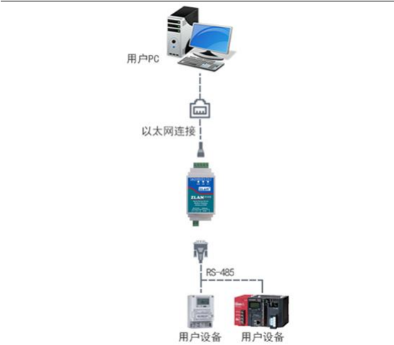 Figure 3 Connection diagram2. Features2.2 Software functions2.3 Advanced software functions3. Technical Parameters
| appearance | |||
| Interface: | 485: Terminal block | ||
| Power supply: | Terminal block type | ||
| Size: | White model L x W x H = 8.9cm×3.7cm×5.9cm | ||
| Communication interface | |||
| Ethernet: | RJ45 interface, 2 KV surge protection | ||
| Serial port: | RS485×1: RXD , TXD , GND | ||
| Serial port parameters | |||
| Baud rate | 300~ 115200bps | Position verification: | None, Odd parity, Even parity, Mark, Space |
| Data bit: | 5th to 9th digit | Fluid control: | No flow control |
| software | |||
| Agreement: | ETHERNET, IP, TCP, UDP, HTTP, ARP, ICMP, DHCP, DNS | ||
| Configuration method: | ZLVirCOM tool, WEB browser, device management function library | ||
| Communication mode: | TCP/IP direct communication, virtual serial port mode | ||
| Operating Mode | |||
| TCP Server, TCP Client (with TCP Server also coexisting), UDP, UDP Multicast | |||
| Power Requirements | |||
| Power Supply: | 9~24V DC | ||
| Environmental Requirements | |||
| Operating Temperature: | -40~85℃ | ||
| Storage Temperature: | -45~ 165℃ | ||
| Humidity Range: | 5~95% Relative Humidity | ||
Instructions for Use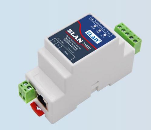 Figure 4 Front view
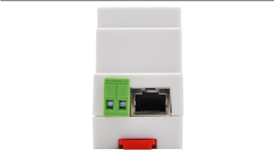 Figure 5 Power Supply, Ethernet PortRS485Using RS485 to connect 485B and 485A, where 485B represents the 485 negative line and 485A represents the 485 positive line; 485 can support up to 32 devices. The maximum communication distance is 1200 meters. Generally, RS485 cable
| Power light | Power indicator light |
| Link light | (1) When the network cable is properly connected, the Link indicator is green. |
| Active light | (1) When the Ethernet port sends data to the serial port, the indicator light is green. The flashing time is longer than the actual communication time |
Shanghai ZLAN Information Technology Co., Ltd
| To determine whether the device has responded to the commands from the host computer. If there is no response, it indicates a serial issue |
Debugging communication method using indicator lights: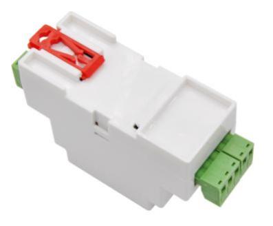 Figure 5: Back of the device4.2 Hardware description for black model
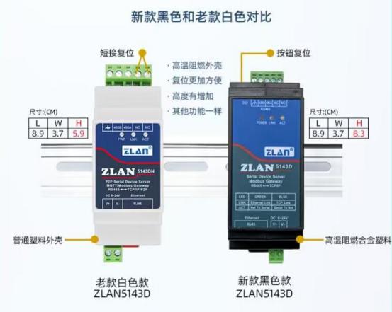 Figure 5 Comparison between black and white models
| comparison item | white version | Black version |
| shell | Common plastics | Flame-retardant alloy plastic, which remains undeformed at high temperatures up to 110 degrees Celsius, and does not contribute to combustion |
| Size | The front dimensions are the same, with a depth of 5.9cm. | The front dimensions are the same, with a depth of 8.3cm. |
| Reset method | Reset by short-circuiting two NC terminals. | Reset via the reset button, which is more convenient. |
| Ethernet port position | On the right. | On the left. |
Other hardware and software functions are the same for both black and white models, and will not be repeated here.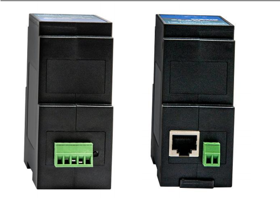 Figure 5: Interface details of the black model.4.3 Hardware connection4.4 Software installationhttp://www.zlmcu.com/download.htmTable 3 ZLVircom Versions
| Software Name | Description |
| ZLVircom Device Management Tool (Non-Installation Version) | The non-installation version does not include virtual serial port functionality. |
| ZLVircom-Device Management Tool (Installation Version) | Installation Version, internally containing ZLVircom_x64.msi and |
Shanghai ZLAN Information Technology Co., Ltd.
| ZLVircom_x86.msi. Install x64 for 64-bit operating systems, |
Simply follow the default prompts during installation. After installation, it will start automatically every time the computer boots up4.5 Parameter configuration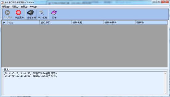 Figure 6 ZLVircom Main Interface
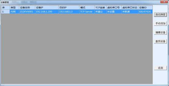 Figure 7 Device List
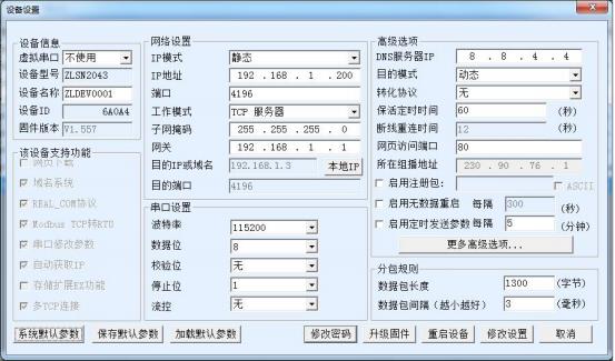 Figure 8: Device Parameters
| parameter name | Value range | meaning |
| Virtual Serial Port | Virtual string that is not used or created | You can bind the current device to a created virtual serial port. |
| Device Model | Only display the models of core modules | |
| Device Name | Any | can give the device a readable name with a maximum length of 9 characters |
| Device ID | The factory-assigned unique ID is non-editable. | |
| Firmware Version | Firmware version of the core module | |
| The device supports | Refer to Table 5 for the functions supported by the device | |
| IP mode | Static, DHCP | Users can choose between static or DHCP (Dynamic Host Configuration Protocol) |
| IP address | IP address of the serial server | |
| Port | 0~65535 | The listening port of the serial server when in TCP Server or UDP mode. When acting as a client, it is best to specify port 0, which helps improve connection speed. When using port 0, the system will randomly assign a local port. The difference between this and a non-zero port is: (1) When the local port is 0, the module will establish a new TCP connection with the PC when restarted, and the old TCP connection may not be closed, potentially resulting in multiple fake connections with the device. Generally, the host computer expects the old connection to be closed when the module is restarted; specifying a non-zero port will close the old connection. (2) When the local port is 0 |
| Work Mode | TCP server mode, TCP client mode, UDP mode | When set as a TCP server, the serial port server waits for a computer connection; when set as a TCP client, the serial port server initiates |
Shanghai ZLAN Information Technology Co., Ltd
| subnet mask | For example: 255.255.255.0 | It must be the same as the subnet mask of the local area network. |
| gateway | For example: 192.168 | It must be the same as the local LAN gateway.. |
| Destination IP or Domain Name | In TCP client or UDP mode, data will be sent to the destination | |
| Destination port | In TCP client or UDP mode, data will be sent to the destination | |
| Baud rate | 1200, 2400, 4800, 7200, 9600, 14400, 19200, 28800, 38400, 57600, 76800, 115200, 230400 | Serial port baud rate |
| data bit | 5, 6, 7, 8, 9 | |
| check digit | None, Even, Odd, Marker, Empty | |
| stop bit | 1, 2 | |
| flow control | No flow control, hard flow control CTS/RTS, hard flow control | Only valid for RS232 serial port |
| DNS server | When the destination IP is described by a domain name, this DNS server IP needs to be filled in. When the IP mode is DHCP, no DNS needs to be specified | |
| Target mode | static, dynamic | In TCP client mode: After using the static destination mode, the device |
| Transformation agreement | NONE, Modbus | NONE indicates that the data forwarding from the serial port to the network is transparent; Modbus TCP<->RTU will directly convert the Modbus TCP protocol into the RTU protocol, facilitating cooperation with the Modbus TCP protocol; RealCOM is designed to be compatible with the old version of the REAL_COM protocol and is a protocol of the virtual serial port type, but |
Shanghai ZLAN Information Technology Co., Ltd
| Agreement. | ||
| Keep-alive timing | 0~255 | Heartbeat interval. (1) When set to 1~255, if the device is in TCP client working mode, it will automatically send TCP heartbeats every "keep-alive timer time". This ensures the TCP validity of the link. When set to 0, there will be no TCP heartbeats. (2) When set to 0~254, if the conversion protocol is set to REAL_COM protocol, the device will send a data packet with a length of 1 and content of 0 every keep-alive timer time, implementing the heartbeat mechanism in the Realcom protocol. When set to 255, there will be no Realcom heartbeat. (3) When set to 0~254, if the device is working as a TCP client, it will send device parameters to the destination computer every keep-alive timer time. When set to 255 |
| Disconnection and reconnection time | 0~255 | When in TCP client mode, if the connection is not successful, a TCP connection will be reinitiated to the computer every "disconnection reconnection time". The value can range from 0 to 254 seconds. If set to 255, it indicates that reconnection will never occur. Note that the first TCP connection (such as when the hardware is powered on, the device is restarted through zlvircom software, or there is no data light) will generally be initiated immediately. Only after the first connection fails will it wait for the "disconnection reconnection time" before attempting again. Therefore, the "disconnection reconnection time" will not affect the network and server under normal conditions |
| Web page access port | 1~65535 | The default is 80. |
| The multicast address where | is used for UDP multicast. | |
| Enable the registration packet. | When a TCP connection is established, send this registration packet to the computer. After enabling the registration packet, the realcom protocol must be selected. | |
| Packet length | 1~1400 | One of the framing rules for serial ports. Upon receiving data of this length, the serial port server sends the received data as a frame to the network |
| Packet interval | 0~255 | Serial port framing rule 2. When the serial port server receives data through its serial port |
Shanghai ZLAN Information Technology Co., Ltd
| When there is a pause and the pause time exceeds a certain threshold, the received |
The functions supported by the device are explained as follows:
| Name | Explanation |
| Webpage download | Support controlling serial port output commands through a webpage. Only products with a suffix of W have this feature |
| Domain Name System | The destination IP can be a domain name (such as the server address starting with www). |
| REAL_COM protocol | A non-transparent serial server protocol, suitable for binding virtual serial ports among multiple serial servers via the Internet. This protocol incorporates the device's MAC address, hence its functionality |
| Modbus TCP to RTU | Only models with the third digit being 4 support this function. It can achieve Modbus TCP conversion |
| Modify serial port parameters | Support serial port AT-like commands for device parameter configuration and reading. |
| Automatically obtain IP | Support DHCP client protocol |
| Storage expansion EX function | Future expansion |
| Multiple TCP connections | Support more than 1 TCP connection when acting as a TCP server. |
| IO port control | Models with the third digit being 4 support arbitrary custom commands to control 8 IO outputs. |
| UDP multicast | UDP multicast |
| Multi-destination IP | supports simultaneous connections to 7 destination IPs when acting as a TCP client. |
| Proxy server | supports proxy server functionality (requires specific model). |
| SNMP functionality | supports SNMP to Modbus RTU protocol conversion. Only those with the suffix -SNMP are supported |
| P2P function | Support the function of accessing devices in any network through P2P traversal technology. |
4.6 TCP communication test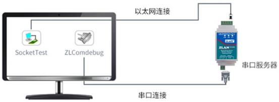 Figure 9 Schematic diagram of TCP communicationhttp://www.zlmcu.com/download/Comdebug.rar"Serial port debugging assistant, and open the corresponding COM port as shown in Figure 6; open TCP&UDP debugging assistant SocketTest."http://www.zlmcu.com/download/SocketTest.rar), and as a TCP client, fill in the destination IP as the IP of the serial server (currently192.168.1.200), and the destination port as 4196, then click the "Open" button. In SocketTest, enter "socket send" and click to send. The data will be transferred to the RS485 interface through the network port of the serial server, and then sent to ZLComDebug, where it will be displayed. Conversely, entering "Comdebug send" in ZLComDebug and clicking to send can also send the data to SocketTest, where it will be displayed.
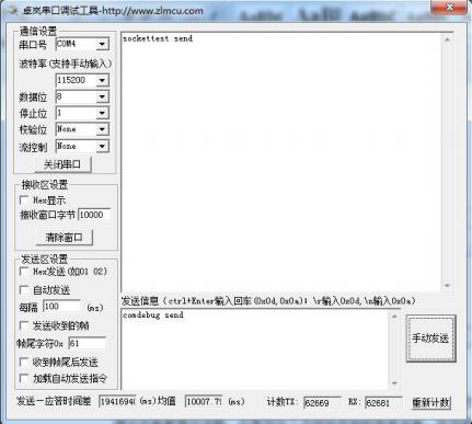 Figure 6: comdebug sending and receiving interface
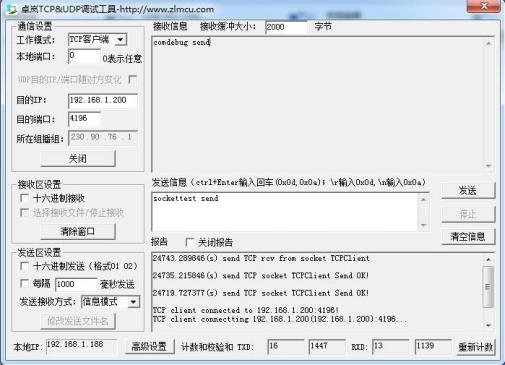 Figure 11: Sockettest sending and receiving interface4.7 Virtual serial port test
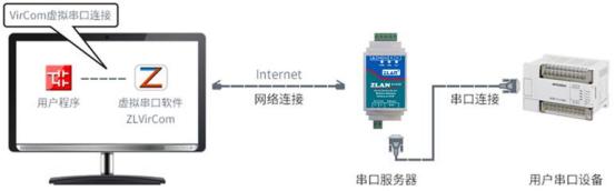 Figure 12: The role of virtual serial port
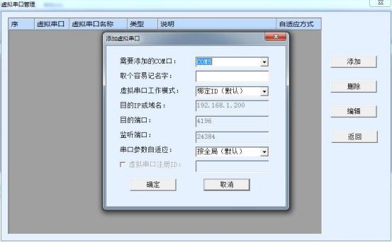 Figure 7: Adding a Virtual Serial Port192.168.1.200The device is connected. At this point, you can use COM5 instead of SocketTest for communication.
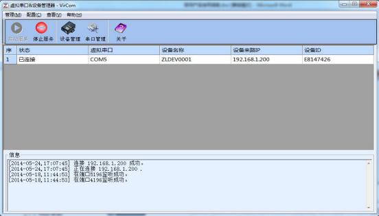 Figure 8: Virtual serial port is connected
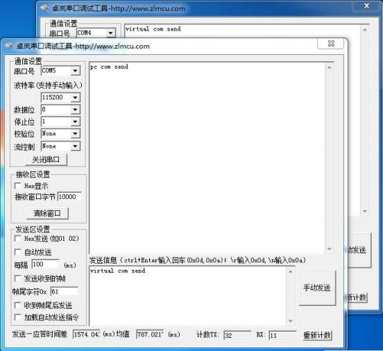 Figure 9: Communication through virtual serial port4.8 Modbus TCP Test
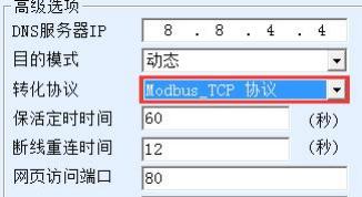 Figure 10: Enabling Modbus TCP Functionality
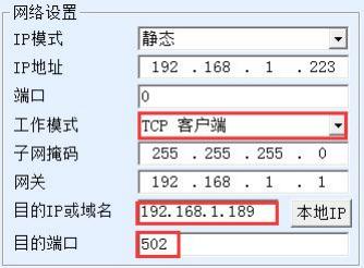 Figure 11: Modbus TCP acting as a client.4.9 Web-based configuration
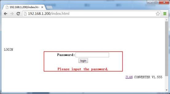 Figure 12
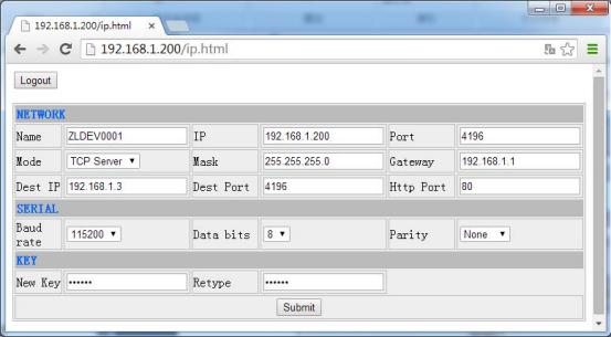 Figure 13 Web Configuration Interface5. Working mode and conversion protocol
| Number | Virtual serial port | Equipment working mode | Transformation agreement | Explanation |
| 1 | Use | TCP server | None | is suitable for user software to open COM port |
| 2 | Use | TCP client | None | Suitable for scenarios where devices actively send data. If a TCP server is chosen, there may be a situation where the device cannot reconnect after being disconnected |
| 3 | do not use | TCP server | Modbus TCP to RTU | The applicable user software is Modbus TCP, and the user device is Modbus RTU. |
| 4 | do not use | TCP client | Modbus TCP to RTU | Applicable to user software being Modbus TCP and user device being Modbus RTU.RTU The situation of the main station. |
| 5 | Use | TCP client | Realcom protocol | Multi-serial port server acting as a TCP client |
Shanghai ZLAN Information Technology Co., Ltd
| Use the Realcom protocol. | ||||
| 6 | do not use | TCP client | None | It is suitable for scenarios where there are numerous devices connected to a single cloud. Generally, the cloud is a public network on the Internet |
| 7 | do not use | TCP server | None | is suitable for scenarios where both the device and the computer are on the same local network, allowing for local monitoring, |
5.1. 5.2. 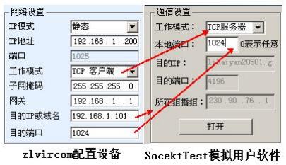 Figure 14 Serial server as a client
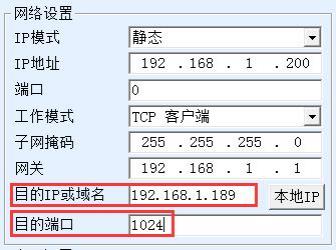 Figure 15: First destination IP and port
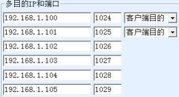 Figure 16: Remaining 2 to 7 IPs and ports
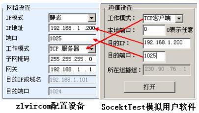 Figure 17 Serial server as server
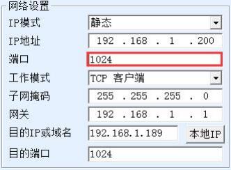 Figure 18: Serving as both a client and a server192.168.1.200Communication is conducted through 1024 ports, and the device also serves as a client connection192.168.1.189The port 1024. It should be noted that since the local port 1024 is occupied by the server, when acting as a client, the local port used is "port + 1", meaning that the software on 192.168.1.189 sees the incoming port of the device as 1024+1=1025.
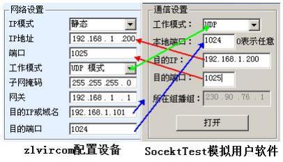 Figure 19 UDP mode parameter configuration5.3. Device connection method
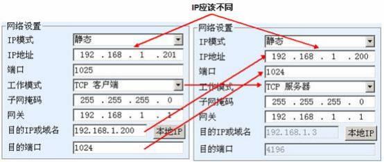 Figure 20 TCP Device Pair Link Parameter Configuration
 Figure 21: Successful check of TCP device pairing
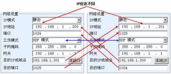 Figure 22: UDP Device Pair Link Parameter Configuration6. equipment debugging6.2.
 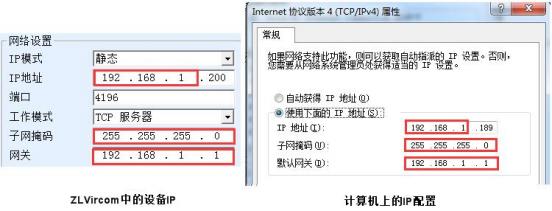 Figure 29: Configured on the same network segment
 Figure 23 Connection status and data transmission and reception status6.3. 6.4.
 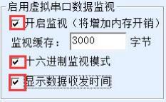 Figure 24: Enable ZLVirocm Monitoring
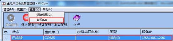 Figure 25: Open ZLVirocm Monitoring
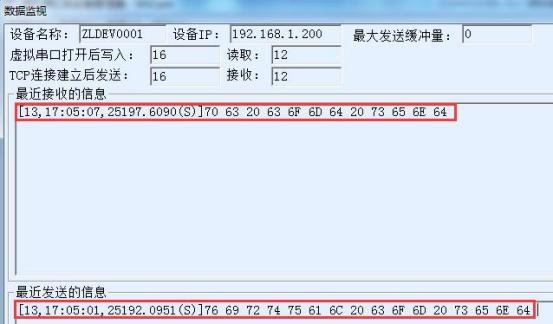 Figure 26 Monitoring and Transmitting Data7. ModbusAdvanced Features7.1. 7.2.
 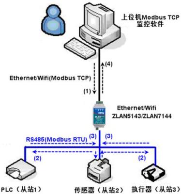 Figure 27: Operating mode of storage-type Modbus gateway7.3.
 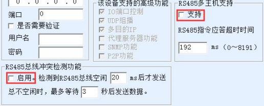 Figure 28 Disable storage-type function7.4.
 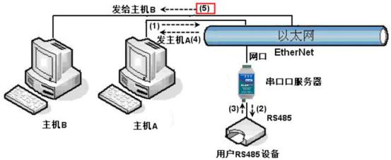 Figure 29 Demonstration of Multi-Host Functionality7.5.
 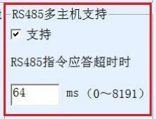 Figure 30 RS485 Multi-host Support
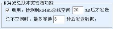 Figure 31 RS485 anti-collision idle time7.6. 7.7. http://www.zlmcu.com/document/Modbus_Gateway.html.
8. Registration packet and heartbeat packet
Figure 31 RS485 anti-collision idle time7.6. 7.7. http://www.zlmcu.com/document/Modbus_Gateway.html.
8. Registration packet and heartbeat packet Figure 32: Send MAC address upon connection
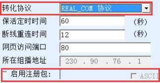 Figure 33: Enabling the realcom protocol
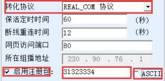 Figure 34: Setting up the registration package8.2.
 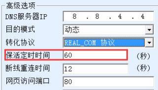 Figure 35 Keep-alive timing
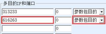 Figure 36 Custom Registration Package9. httpdClient communication function10. MQTTgatewayhttp://www.zlmcu.com/document/Usage_of_MQTT_Gateway.html"Usage of ZLAN MQTT and JSON to Modbus Gateway"http://www.zlmcu.com/document/MQTT&JSON_to_Modbus.html;
11. JSONturn Modbus RTUFor JSON to Modbus RTU conversion and related JSON usage, please refer to "JSON Data Collection Gateway"http://www.zlmcu.com/document/jsondata.html";Use of ZLAN Cloud and Data Collection Equipment"http://www.zlmcu.com/document/zlancloud.html";645 Method for uploading instruments in JSON format"http://www.zlmcu.com/document/645_Instrument_JSON.html; "ZLAN MQTT and JSON to Modbus Gateway Usage"http://www.zlmcu.com/document/MQTT&JSON_to_Modbus.html;
12. NTPTime Functionhttp://www.zlmcu.com/document/zlan_NTP.html.
13. Modify parameters of network port14. Device management function libraryhttp://zlmcu.com/download.htmSearch for "Device Management Function Library" on the page. For details, please refer to "ZLAN WinP2p and Device Management Development Library"15. Modify parameters through serial port16. Remote device management
Figure 36 Custom Registration Package9. httpdClient communication function10. MQTTgatewayhttp://www.zlmcu.com/document/Usage_of_MQTT_Gateway.html"Usage of ZLAN MQTT and JSON to Modbus Gateway"http://www.zlmcu.com/document/MQTT&JSON_to_Modbus.html;
11. JSONturn Modbus RTUFor JSON to Modbus RTU conversion and related JSON usage, please refer to "JSON Data Collection Gateway"http://www.zlmcu.com/document/jsondata.html";Use of ZLAN Cloud and Data Collection Equipment"http://www.zlmcu.com/document/zlancloud.html";645 Method for uploading instruments in JSON format"http://www.zlmcu.com/document/645_Instrument_JSON.html; "ZLAN MQTT and JSON to Modbus Gateway Usage"http://www.zlmcu.com/document/MQTT&JSON_to_Modbus.html;
12. NTPTime Functionhttp://www.zlmcu.com/document/zlan_NTP.html.
13. Modify parameters of network port14. Device management function libraryhttp://zlmcu.com/download.htmSearch for "Device Management Function Library" on the page. For details, please refer to "ZLAN WinP2p and Device Management Development Library"15. Modify parameters through serial port16. Remote device management Figure 37: Automatic Search
 Figure 38: Manual Addition
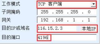 Figure 39: Client
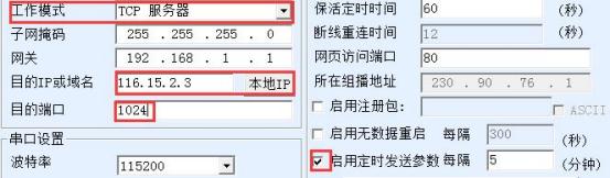 Figure 40: Timed sending parameters17. Firmware upgrade method
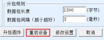 Figure 41 Upgrade button
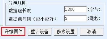 Figure 42 Upgrade button
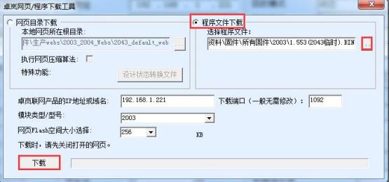 Figure 43 Firmware upgrade method for ZLSN2003
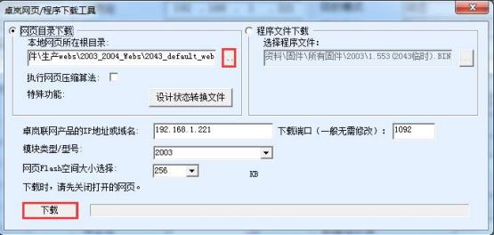 Figure 44 ZLSN2003 web upgrade method
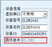 After completing level 45, check the firmware version


Leave a Reply