

Introduction
The MODBUS client interface provides an interface that enables user applications to generate requests for various MODBUS services, including accessing MODBUS application objects. Although illustrated with examples in the implementation model, the MODBUS client interface (API) is not described here.
The IP address of the remote device is used to locate the established TCP connection. When establishing multiple connections with the same remote device, it is necessary to select one of the connections for sending MODBUS messages. Different selection strategies can be adopted, such as the earliest connection or the first connection. Throughout the MODBUS communication process, the connection must always remain open. As described in the following chapters, a client can initiate multiple transactions to a server without waiting for the completion of preceding transactions.
These parameters allow setting high limits for socket interfaces used for sending and receiving. Flow control management can be achieved by adjusting these parameters. The size of the receive cache is the maximum value of each advertised window for each connection. To improve performance, it is necessary to increase the size of the socket cache. Otherwise, these values must be less than the resources of the internal drive in order to close the TCP window before the internal drive's resources are exhausted.
Send MODBUS request ADU to the TCP management module, which is responsible for finding the correct TCP socket for the remote server. In addition to MODBUS ADU, the destination IP address must also be passed.
- The following diagram describes the main processing steps taken by the server to obtain MODBUS requests from TCP management, analyze the requests, process the required operations, and return MODBUS responses.
- This model is independent of the choice of implementation, such as OS type, storage management, etc. To ensure this independence, generic interface layers are used between the TCP management layer and communication layer, as well as between the communication layer and user application layer.
- Step 4: Send a response over the network using CInterfaceResponseMessaging (using the m_MODBUSResponse method). Process the connection object (restore connection descriptors, etc.) through the m_SendData method and send data over the network.
Client/Server Model
MODBUSMessage transmission service provides client/server communication between devices, These devices are connected in oneEthernet (Ethernet) TCP/IPon the internet.
This client/server mode is based on four types of messages:
- MODBUS Request
- MODBUS confirm
- MODBUS Instructions
- MODBUS Response
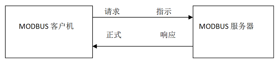
MODBUSA request is a message sent by a client over the network to initiate transaction processing
MODBUSThe indication is a request message received by the server
MODBUSResponse is the response information sent by the server
MODBUSConfirm that the response information is received on the client side
MODBUSMessage transmission service (Client/Server Model) Used for real-time information exchange:
- Between two device applications
- Between device applications and other devices
- inHMI/SCADABetween applications and devices
- in aPCBetween a device program that provides online services
Normative reference documents
This chapter provides a list of favorite files to read before this document:
[2] MODBUSProtocol specifications
[4] RFC1122
abbreviation
ADU -- Application data unit
IETF -- Internet Engineering Task Force
IP -- internet protocol
MAC -- Media Access Control
MB -- MODBUS
MBAP -- MODBUSagreement
PDU -- Protocol Data Unit
PLC -- Programmable Logic Controller
TCP -- Transmission Control Protocol
BSD -- Berkeley Software Distribution
MSL -- Maximum lifespan
Background Overview
Protocol Description
Overall communication structure
MODBUS TCP/IPThe communication system can include different types of devices:
- Connect toTCP/IPnetworkMODBUS TCP/IPClient and server devices
- Interconnected devices, for example: InTCP/IPA bridge that interconnects networks and serial link subnets, Router or gateway, connection, This subnet allows forMODBUSConnect the serial link client and server terminal devices together.
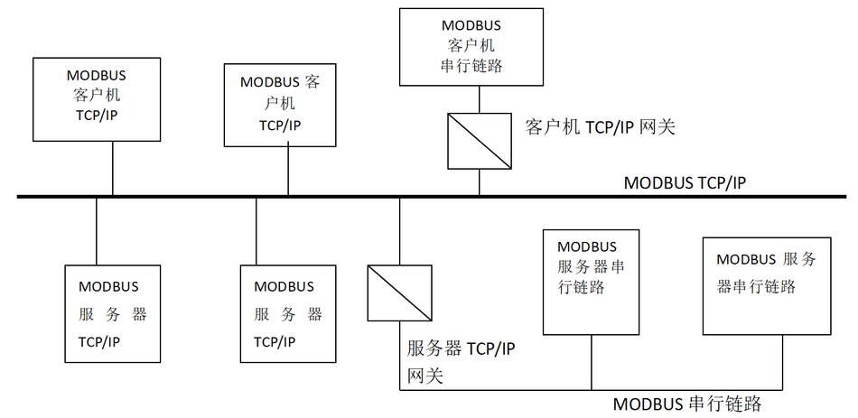
Figure 1:MODBUS TCP/IPCommunication structure
MODBUSThe protocol defines a protocol that is independent of the underlying communication layerSimple Protocol Data Unit (PDU) . On a specific bus or networkMODBUSProtocol mapping can be used inApplication data unit (ADU) Introduce some additional fields on top.

Figure 2:GeneralMODBUSframe
StartMODBUSEstablishment of client for transaction processingMODBUSApplication data unit. This function code indicates to the server which operation to perform.
TCP/IPonMODBUSApplication data unit
This section describesMODBUS TCP/IPConducted in the networkMODBUSEncapsulation of requests or responses.
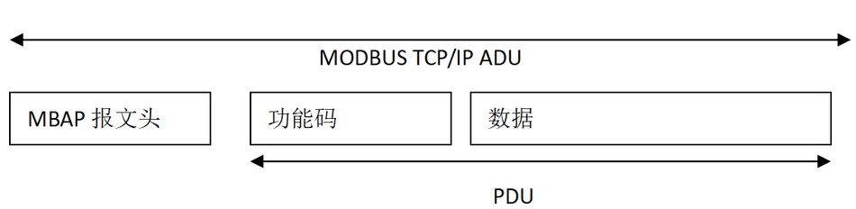
Figure 3:TCP/IPonMODBUSRequest/Response
inTCP/IPUsing a dedicated message header recognition methodMODBUSApplication data unit. This type of message header is referred to asMBAPMessage header (MODBUSProtocol message header) .
This type of message header provides some information for use on serial linksMODBUS RTUDifferences in Comparing Application Data Units:
- UseMBAPReplace the single byte unit identifier in the message headerMODBUSCommonly used on serial linksMODBUSFrom address domain. This unit identifier is used for device communication, These devices use a singleIPAddress supports multiple independent addressesMODBUSTerminal unit, for example: bridge, Router and Gateway.
- Design all messages in a way that the receiver can verify the completion of the messageMODBUSRequest and response. RegardingMODBUS PDUFor function codes with fixed length, Just the function code is enough. For function codes that carry variable data in requests or responses, The data domain includes the number of bytes.
- when inTCPCarry onMODBUSWhen,Even if the message is divided into multiple packets for transmission, Working inMBAPThe message header carries additional length information, So that the receiver can identify the message boundary. The existence of explicit and implicit length rules andCRC-32The use of error check codes (On Ethernet) Will cause minimal undetected interference to request or response messages.
MBAPMessage header description
MBAPThe message header includes the following fields:
| domain | Length | Description | client | Server |
| Transaction Element Identifier | 2bytes | MODBUSIdentification code for request/response transaction processing | Client startup | The server replicates from the received request again |
| Protocol Identifier | 2bytes | 0=MODBUSagreement | Client startup | The server replicates from the received request again |
| Length | 2bytes | The quantity of the following bytes | Client startup (Request) | Server (Response) Start |
| Unit identifier | 1bytes | Identification code of remote slave station connected on serial link or other bus | Client startup | The server replicates from the received request again |
The message header is 7 bytes long:
transaction ID : Used for transaction pairing. In response, MODBUSTransaction identifier for server replication request.
Protocol Identifier: Used for multiplexing within the system. Identify by value 0MODBUSagreement.
Length: The length field is the number of bytes in the next field, Including unit identifiers and data fields.
Unit identifier: For routing within the system, Use this domain. Specially designed for use over EthernetTCP-IPNetwork andMODBUSGateway pair between serial linksMODBUSorMODBUS+Communication of serial link slave station. MODBUSThe client sets this domain in the request, In the response, the server must use the same value to return this field.
In the registration process502Utilize on portTCPSend allMODBUS/TCP ADU.
Note: UseBig-endianEncoding different domains.
MODBUSFunction code description
inMODBUSProtocol specifications[2]The document provides a detailed explanationMODBUSStandard functional codes used on application layer protocols.
Functional Description
What is provided hereMODBUSThe component structure is a combination ofMODBUSThe client also includesMODBUSGeneral model of server components, Suitable for any device.
Some devices may only provide server or client components.
The first part of this chapter, Provide an information aboutMODBUSA brief overview of the structure of message transmission service components, then, Provide a description of each component within the structural model.
MODBUSComponent Structure Model
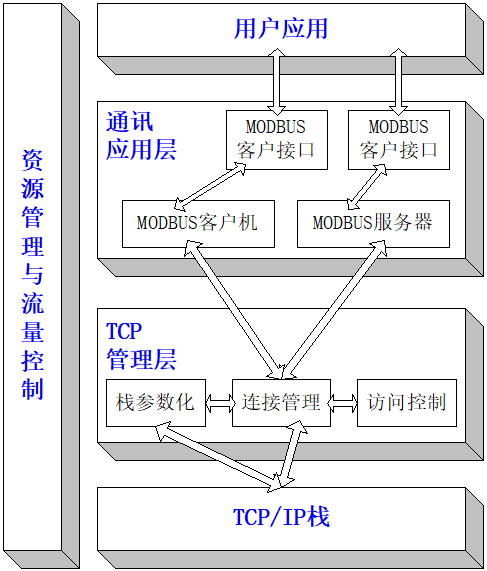
Picture4 MODBUSConceptual structure of message transmission service
- Communication application layer
oneMODBUSThe device can provide a client and/or serverMODBUSinterface.
Can provide oneMODBUSBackend interface, Allow indirect access to user application objects.
This interface consists of four parts: Discrete input, Discrete output (coil) , Register input and register output. The mapping between this interface and user application data must be defined (Local issues) .
| Basic Data Table | object type | attribute | Instructions |
| Discrete input | 1bit | read-only | This type of data can come fromI/Osystem |
| coil | 1bit | Read Write | This type of data can be modified by applications |
| Register input | 16Positional character | read-only | This type of data can come fromI/Osystem |
| Register output | 16Positional character | Just write | This type of data can be modified by applications |
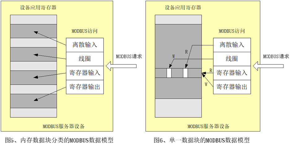
- MODBUSclient
MODBUSThe client allows users to clearly control the exchange of information with remote devices through the application. MODBUSThe client applies to the user based on their applicationMODBUSGenerate a set of parameters included in the requirements sent by the customer interfaceMODBUSRequest.
MODBUSThe client calls aMODBUSTransaction processing, Transaction management includesMODBUSConfirmation waiting and processing.
- MODBUSClient interface
MODBUSThe client interface provides an interface, Enable user applications to generate access to, includingMODBUSVarious types including application objectsMODBUSService Request. Although illustrated with examples in the implementation model, butMODBUSClient interface (API) Not described here.
- MODBUSServer
Received oneMODBUSRequest later, Module activates a local operation for readingWrite, writeOr complete other operations. The handling of these operations is transparent to application developers. MODBUSThe main function of a server is to wait for information fromTCP502The mouthMODBUSRequest, Handle this request, Then generate aMODBUSresponse, The response depends on the condition of the equipment (Field environment) .
- MODBUSBackend interface
MODBUSThe backend interface is aMODBUSThe interface between the server and the user application that defines the application object.
- TCPmanagement
One of the main functions of message transmission services is to manage the establishment and termination of communication, Management is built uponTCPConnected data flow.
- Connection Management
On the client and serverMODBUSCommunication between modules requires callingTCPConnection management module. It is responsible for comprehensive management of message transmissionTCPConnect.
There are two possibilities in connection management: User application self-managementTCPConnect, Or all connections can be managed by this module, And be transparent to user applications. The latter solution has poor flexibility.
TCP 502The listening of the mouth is forMODBUSCommunication reservation. In default state, Force listening on this port. However, Some markets or applications may require other ports asTCPAboveMODBUSFor communication purposes. When needed with non Schneider (Schneider) When products are interoperable, This is exactly the case, for example: In building control. for this, strongly recommend: Both the client and server should provide users with access toTCPOn the sloganMODBUSThe possibility of configuring parameters. What matters: Even in a specific application, forMODBUSOther services have been configuredTCPServer port, Except for some specific application ports, TCPServer502The mouth must still be usable.
- Access Control Module
In certain crucial occasions, Unnecessary hosts must be prohibited from accessing internal data of the device. That's why a secure mode is needed, This is also the reason for implementing secure processing when needed.
- TCP/IPStack layer
TCP/IPThe stack can be configured with parameters, In order to facilitate data flow control, Address management and connection management are adapted to different constraints of specific products or systems. generally speaking, BSDThe socket interface is used for managementTCPConnect.
- Resource management and data flow control
To balanceMODBUSThe data flow of incoming and outgoing message transmission between the client and server, inMODBUSAll layers of the message transmission stack are equipped with data flow control mechanisms. The resource management and data flow control module is first based onTCPInternal data flow control, Some data flow control of additional data link layer, And data flow control at the user application layer.
TCPConnection Management
Connection management module
Overall description
MODBUSCommunication requires establishing a connection between the client and serverTCPConnect.
The establishment of the connection can be directly implemented by the user application module, It can also be done byTCPAutomatic completion of connection management module.
in the first instance, The user application module must provide an application programming interface, In order to fully manage connections. This approach provides flexibility for application developers, but needTCP/IPExpertise in mechanism.
In the second option, TCPConnection management does not appear at all, User applications only need to send and receiveMODBUSmessage. TCPThe connection management module is responsible for establishing new ones when neededTCPConnect.
TCPThe definition of the number of client and server connections is not within the scope of this document (In this article, the use ofn) . According to equipment capability, TCPThe number of connections will vary.
Implementing rules:
- If there is no clear user demand, Suggest using automaticTCPConnection Management
- Suggestion: Open and maintain connection with remote devices, And don't do it every timeMODBUS/TCPOpen and close connections during transaction processing. Note:However, MODBUSThe client must be able to receive shutdown requests from the server, And close the connection. When needed, The connection can be reopened.
- Suggestion: eachMODBUSCustomers should at least open and communicate with the remote endMODBUSserver'sTCPConnect (sameIPaddress) . Establishing a connection for an application is a good choice.
- severalMODBUSTransaction processing can be done in the same placeTCPConnected and activated simultaneously: If in this way, MODBUSThe transaction identifier must be used to uniquely identify the match between the request and response.
- At two remote locationsMODBUSDevice (A client and a server) In the case of bidirectional communication between them, It is necessary to establish separate connections for the client data stream and the server data stream.
- oneTCPOnly one frame can be transmittedMODBUS ADU. Suggestion: Don't be in the same placeTCP PDUSending multiple requests or responses in the middle.
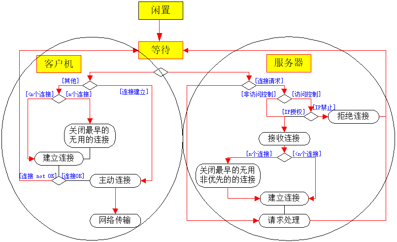
Figure 7:TCPConnection management operation diagram
1. ExplicitTCPConnection Management
The user application module is responsible for managing allTCPConnect: Establishing active and passive connections, Connection completed………. Manage all connections between the client and server in this way. BSDSocket interface is used in user application modules for managementTCPConnect. This scheme provides complete flexibility, But it also means that application developers need to have sufficient relevant skillsTCPThe knowledge.
Considering the capabilities and requirements of the equipment, Restrictions on the number of connections between the client and server must be configured.
2. AutomaticTCPConnection Management
TCPConnection management is completely transparent to user application modules. The connection management module can accept a sufficient number of client/server connections. otherwise, There must be an implementation mechanism when exceeding the authorized number of connections. under these circumstances, We recommend: Close the earliest established unused connection.
After receiving the first packet from a remote client or local user application, A connection was established with the remote object. If a network terminates or a local device decides to terminate, This connection will be closed. When receiving a connection request, Access control options can be used to prevent unauthorized customers from accessing the device.
TCPThe connection management module adopts a stack interface (UsuallyBSDsocket API ) Come andTCP/IPStack communication.
To maintain compatibility between system requirements and server resources, TCPManagement will maintain two connectionsLibrary.
- the first oneLibrary (Priority ConnectionLibrary) Composed of connections that are never actively closed locally. A configuration must be provided to establish this library. The principle of implementation is to associate every possible connection of this library with a specific oneIPLink addresses together. Having thisIPThe device with the address is called“marked”. Any one being“marked”New connection requests from the device must be received, And retrieve it from the priority connection library. It is also necessary to set the maximum number of connections allowed for each remote device to establish, To avoid using all connections in the priority connection library for the same device.
- The second library (Non priority connection library) Including connections to non tagged devices. The rule adopted here is: When there are new connection requests from non tagged devices, And when there are no available connections in the library, Close the connection established earlier.
A configuration can be provided as an option to allocate the number of available connections in each library. However (Non mandatory) , if needed, Designers can set the number of connections during the design phase.
Connection Management Description
- Connection establishment
MODBUSThe message transmission service must be provided within502Provide a listening socket orally, Allow receiving new connections and exchanging data with other devices.
When the message transmission service needs to exchange data with a remote server, It must be connected to the remote end502Establish a new customer connection, In order to exchange data over long distances. The local port must be higher than1024, And each customer connection is different.
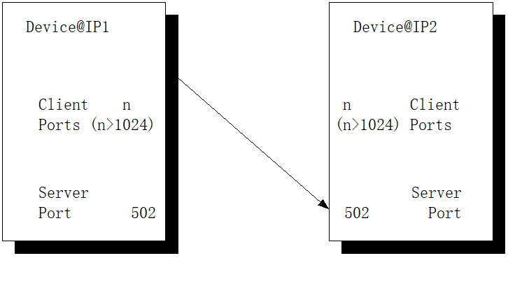
Figure 8:MODBUS TCP/IPConnection establishment
If the number of connections between the client and server is greater than the authorized number of connections, The earliest established useless connection is closed. Activate the access control mechanism to check the remote client'sIPIs the address authorized. If unauthorized, Will reject new connections.
- MODBUSdata transformation
Based on the correct one that has already been openedTCPConnect and sendMODBUSRequest. Remote devicesIPThe address is used to find the builtTCPConnect. When establishing multiple connections with the same remote device, You must choose one of the connections to sendMODBUSmessage, Different selection strategies can be adopted, for example: The earliest connection, The first connectionInMODBUSThroughout the entire process of communication, The connection must always remain open. As described in the following chapters, A client can initiate multiple transactions to a server, And there is no need to wait for the processing of preceding things to end.
- Connection closed
When there is a conflict between the client and serverMODBUSAt the end of communication, The client must close the connection used for communication.
Operation modeTCPThe impact of connectivity
Certain operating modes (Communication between two operation endpoints is disconnected, Fault and restart of an endpoint, ………) will meetTCPConnection has an impact. A connection can be considered closed or terminated abnormally on one side without confirmation from the other side, Call this connection“Half open”The Connection.
This chapter describes the main operating modes for eachcharacteristic. Assuming that both ends of the connection are connected using“ Stay connected ”TCPmechanism.
Communication between the two operating terminals is disconnected
The reason for communication disconnection may be the disconnection of the Ethernet connection cable on the server side. expectedcharacteristicYes:
- If there is no data packet being sent on the connection:
If the duration of communication disconnection is shorter than“Stay connected”The value of the timer, Will not detect communication disconnection. If the communication disconnection time exceeds“Stay connected”The value of the timer, Return an error toTCPadjoining course, Reset the connection through it.
- If sending some data packets before and after disconnection:
TCPRetransmission algorithm (JacobsonAlgorithm, KarnAlgorithm and index compensation algorithm) activated. This may lead to“Stay connected”Before the timer expiresTCPStack connection layer reset.
Server side failures and restarts
After server failure and restart, The client is in“Half open”Connection status. expectedcharacteristicYes:
- If no data packet is sent on a semi open connection:
as long as“Stay connected”The timer is still counting, From the perspective of the client, The connection ishalfopen. afterwards, Will return an error toTCPmanagement, Reset the connection through it.
- If sending some data packets on a semi open connection:
The server is receiving data on a non-existent connection. TCPSend a reset to the stack of layersInstructionTo close the semi open connection of the client.
Client side faults and restarts
After client machine failure and restart, The server side is located at“Half open”Connection status. expectedThe state ofYes:
- If no data packet is sent on a semi open connection:
as long as“Stay connected”The timer is still counting, From the server-side perspective, This connection ishalfopen. afterwards, Will return an error toTCPmanagement, Reset the connection through it.
- If in“Stay connected”Before the timer completes counting, The client opens a new connection:
It must be studied in two situations:
- The opened connection has the same characteristics as the partially opened connection on the server side (Same source and destination port, Same source and purposeIPaddress) , So, After timeout of connection establishment (In most cases, Berkeley's implementation is75ms) , TCPThe stack layer will not be able to open connections. To avoid being unable to communicate for a long timeout period, Suggestion: After restarting on the client side, Ensure to establish a connection using a different source number than the original connection.
- The opened connection has different characteristics from the partially opened connection on the server side (Different source ports and the same destination port, Same source and purposeIPaddress) , So, inTCPOpen a connection on the stack layer, And towards the server sideTCPManagement sends signals.
If the server sideTCPThe management only supports one remote clientIPAddress Connection, So you can close the original semi open connection, Use a new connection.
If the server sideTCPManagement supports multiple remote clientsIPAddress Connection, So the new connection remains open, The original connection remains partially open, until“Stay connected”Timer timer ends, at this moment, Will return an error toTCPmanagement. afterwards, TCPManagement will be able to reset existing connections.
Access Control Module
The purpose of this module is to check every new connection, Compare with a legally authorized remoteIPAddress List, It can authorize or prohibit a remote client'sTCPConnect.
In the crucialoccasion, Application developers need to choose an access control module to ensure network access. under these circumstances, Need to address each remote locationIPAuthorize or prohibit access. The user needs to provide aIPList of addresses, And specifically indicate eachIPIs the address legally authorized. By default, In safe mode, User not configuredIPAll addresses are prohibited. So, By utilizing access control mode, Close from unknown sourcesIPAccess connection of address.
TCP/IPThe use of stack
TCP/IPThe stack provides an interface, Used to manage connections, Sending and receiving data, Parameter configuration can also be performed, To make the stackCharacteristics ofAdapt to the limitations of devices or systems.
The purpose of this chapter is to provide an overview of stack interfaces, And some information related to stack parameter configuration. The overall overview mainly includesMODBUSSome characteristics used in message transmission.
For more information, Suggested readingRFC 1122, thisRFC 1122Provides manufacturers and developers with a guide to Internet communication software. RFC 1122It details the standard protocol that a host connected to the Internet must use, And a clear set of requirements and options.
The stack interface is generally based on the description in this documentBSD (Berkeley software allocation code) interface.
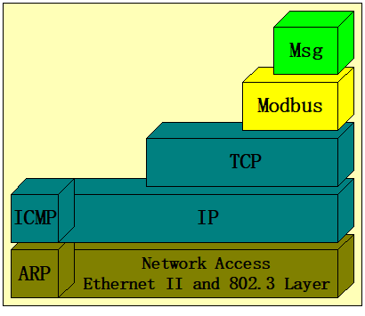
BSDApplication of Socket Interface
Note:someTCP/IPStack proposes other types of interfaces from a performance perspective. MODBUSThe client or server can use these specific interfaces, However, this use is not described in this document.
A socket is a communication endpoint, It is a fundamental building block in communication. Sending and receiving data through sockets can perform aMODBUSCommunication. TCO/IPThe library only provides usageTCPStream sockets that provide connection based communication services.
socket()Function used to create sockets. The returned socket number is used by the creator to access the socket. There is no address when creating the socket (IPAddress and slogan) . Until a port is bound to the socket, Only then can data be received.
bind()Function used to bind a slogan to a socket. bind()The function establishes a connection between the socket and the specified identifier.
To initialize a connection, The client must sendconnect()Function to specify socket size, remote endIPAddress and remote listening slogan (Active connection establishment) .
To complete the connection, The server-side must sendaccept()Function specified beforelisten()The socket number specified in the call (Passive connection establishment) . A new socket has been created, And have the same characteristics as the initial one. This new socket is connected to the client's socket, And return the socket number to the server side. so, Release initial socket, For use by other clients who wish to connect to the server.
inTCPAfter the connection is established, Data can be transmitted immediately. WillSend()andrecv()The function is specifically designed to be used with already connected sockets.
setsockopt()The function allows the creator of a socket to create several options using the socket. These options describe the operational characteristics of sockets.
select()The function allows programmers to test events on all sockets.
shutdown()Function allows the user of the socket to terminatesend()andrecv().
Once the socket is no longer needed, can be usedclose()Function to discard socket description information.
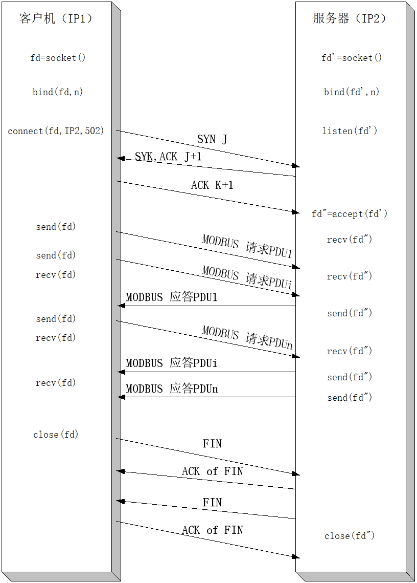
Figure 9:MODBUSinformation switching
The above figure shows the complete communication between the client and serverMODBUScommunication process. Establish a connection on the client machine, Send 3 to the serverMODBUSRequest, Without waiting for the response of the first request to arrive. After receiving all the responses, The client successfully closed the connection.
TCPLayer parameter configuration
can be adjustedTCP/IPSome parameters of the stack to make its characteristics meet the limitations of the product or system. TCPThe following parameters of the layer can be adjusted:
- Parameters for each connection
SO-RCVBUF, SO-SNDBUF:
These parameters allow setting high limits for socket interfaces used for sending and receiving. Flow control management can be achieved by adjusting these parameters. The size of the receiving cache is equal to each connectionadvertised windowThe maximum value. To improve performance, The size of the socket cache must be increased. otherwise, These values must be less than the resources of the internal drive, In order to shut down before the internal drive's resources are exhaustedTCPwindow.
The size of the receiving cache depends onTCPwindow size, TCPThe maximum segment size and the time required to receive input frames. Due to the size of the largest segment being300a character (oneMODBUSRequest requires maximum256character+MBAPMessage header) ,If 3 frames are needed for caching, The size of the socket cache can be adjusted to900Words.To meet the maximum caching requirements and scheduled time, can be increasedTCPWindow size.
TCP-NODELAY:
Usually, Small message (called: tinygrams) In the local area network (LAN) The transmission on will not cause any problems, Because most LANs are not congested, but, thesetinygramsIt will cause congestion on the wide area network. One called“NAGLEAlgorithm”The simple solution is: Collect small amounts of data, When the previous messageTCPConfirm arrival and send separately.
In order to achieve better real-time performance, Suggestion: Sending small amounts of data directly, Don't try to collect it into a segment before sending it. That's why it's recommended to enforceTCP-NODELAYoption, This option disables the connection between the client and server“NAGLEAlgorithm”.
SO-REUSEADDR:
WhenMODBUSThe server shuts down a remote client initiated systemTCPWhen connecting, At this connection“Time waiting”Status (twoMSL: Maximum lifespan) During the process, The local port number used for this connection cannot be used again to open a new connection.
Suggestion: Connect to each client and server, indicateSO-REUSEADDRoption, By circumventing this restriction. This option allows assigning a slogan to oneself, It serves as a part of the connection2MSLDuring this period, wait for the client and listen on the socket interface.
SO-KEEPALIVE:
TCP/IPIn the default state of the protocol, Not through idleTCPConnect to send data. Therefore, If inTCPThe connection process did not send any data, in twoTCPThere is no data exchange between modules. This assumes that both the client-side application and the server-side application use counters to detect the viability of connections, In order to close the connection.
Suggestion: Both ends of the client server connection are connected usingKEEPALIVEoption, In order to query the other end and determine if the other end has malfunctioned and crashed, Or malfunction and restart.
However, We must bear in mind, adoptKEEPALIVEMay cause a very good connection, Communication interruption in case of momentary malfunction, If the duration of the keep connected timer is too short, Will occupy unnecessary network bandwidth.
- wholeTCPLayer parameters
TCPConnection establishment timeout:
Most of the systems launched by Berkeley set the time limit for establishing new connections as75In seconds,This default value should be suitable for real-time application limitations.
Maintain connection parameters:
The default idle time for the connection is 2 hours. Exceeding this idle time will trigger a keep connected probing process. After the first attempt to maintain connection, Within the maximum number of times, every75Send a probe in seconds, Until receiving a response to the probing.
The maximum number of keep connection probes sent on an idle connection is 8 times. If no response is received after sending the maximum number of probing attempts, TCPSend an error signal to the application, The application decides to close the connection.
Timeout and Resend Parameters:
If one is detectedTCPMessage loss, Resend this message. One of the methods to detect loss is to manage resend timeouts (RTO) , If no confirmation is received from the remote end, Timeout termination.
TCPconductRTODynamic evaluation. for this, Measure round-trip time after sending each non resend message(RTT). round-trip time (RTT) It refers to the time it takes for a message to arrive at a remote device and receive a confirmation from the remote device. The round-trip time of a connection is dynamically calculated, However, IfTCPCannot be obtained within 3 secondsRTTThe estimate, then, Just set it upRTTThe default value is 3 seconds.
If it has already been estimatedRTO, It will be used for sending the next message. If estimatedRTONot receiving confirmation of the next message before termination, EnableIndex compensationAlgorithm. Within a specific time period, Allow maximum resending of the same message. afterwards, If no confirmation is received, Connection terminated.
It is possible to set the maximum number of retransmissions and the maximum time for retransmissions before connection termination for certain stacks.
inTCPSome resend algorithms are defined in the standard:
- Jacobson RTOEstimation algorithmUsed to estimate resend timeout(RTO);
- KarnAlgorithmpoint out, In the resend segment, Should not be carried outRTOestimate;
- Index compensation algorithmdefinition: Regarding64Resend every time within the maximum time limit of seconds, Double resend timeout;
- Fast Resend AlgorithmAllow resending after receiving 3 duplicate confirmations. Consider this algorithm because: InLANUp,Detection that may result in packet loss is faster than waitingRTOTermination detection.
inMODBUSImplementation in progress, Recommend using these algorithms.
IPParameter configuration of layers
IPparameter
The following parameters must be inMODBUSimplementedIPConfigure layers:
- LocalIPaddress: IPThe address can beA, BOr a type of C.
- subnet mask: Can be based on various reasons, willIPThe network is divided into subnets: Using different physical media (for example: Ethernet, Wide Area Network, etc) , More effective use of network addresses, And the ability to control network traffic. The subnet mask must match the localIPThe type of address is consistent.
- Default gateway: The default gatewayIPThe address must match the local addressIPAddress within the same subnet. Prohibited from use0.0.0.0The value of. If no gateway is defined, So this value can be set as127.0.0.1Or locallyIPaddress.
Note:MODBUSreportThe text transmission serviceIPNo segment functionality is required on the layer.
Should utilize local resourcesIPaddress, Subnet mask and provincial missing gateway (different from0.0.0.0) Configure LocalIPEnd.
Communication application layer
MODBUSclient
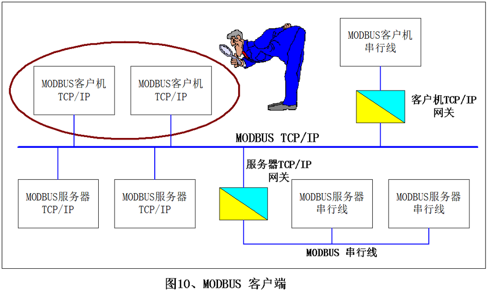
Picture10: MODBUSclient
MODBUSClient Design
MODBUS/TCPThe protocol enables simple design of a client. The following diagram illustrates the client sendingMODBUSRequest and processMODBUSThe main processing procedure for response.
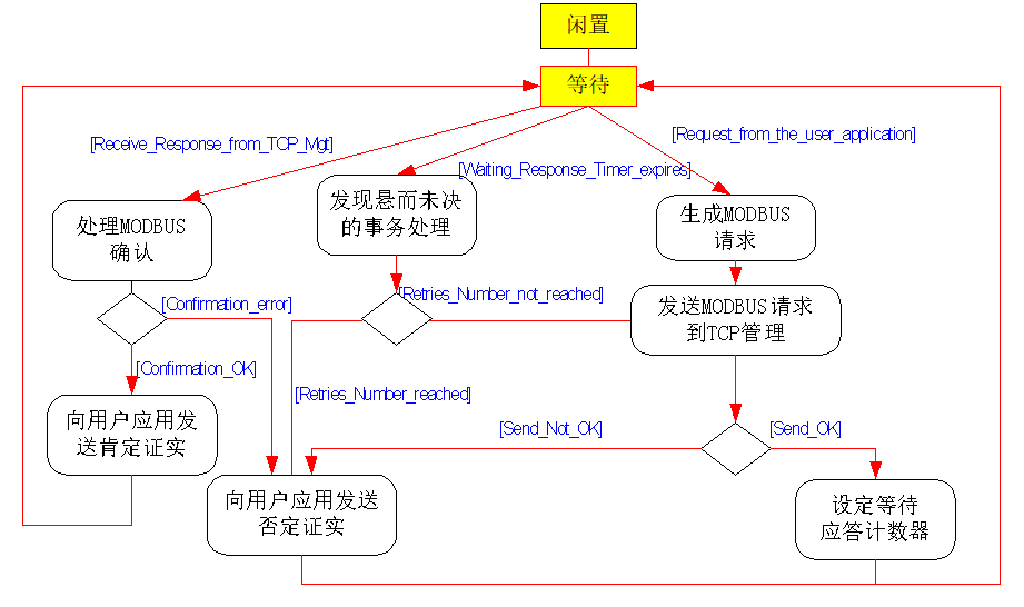
Picture11: MODBUSClient operation diagram
oneMODBUSThe client can receive three types of events:
- A new requirement for sending requests from user applications, under these circumstances, Must be rightMODBUSRequest encoding, And use itTCPThe management component service is sent over the networkMODBUSRequest. lower level (TCPManagement Module) It will return an error message, These error messages are due toTCPCaused by connection errors or other incorrect information.
- FromTCPA response from management, under these circumstances, The client must analyze the content of the response, And send a confirmation to the user application.
- Expired due to no response. You can send a retry message through the network, Or send a negative confirmation to the user application.
Note:These retries are caused byMODBUSStarted by the client, Can be done withoutTCPUnder confirmed circumstancesTCPUse layers to perform other types of retries.
MODBUSGeneration of requests
After receiving the demand from the user application, The client must generate aMODBUSRequest, And send it toTCPManagement.
Can generateMODBUSRequest to decompose into several subtasks:
- MODBUSInstantiation of transaction processing, Enable the client to store all necessary information, In order to match the response with the corresponding request, And send a confirmation to the user application.
- MODBUSRequest (PDU+MPABMessage header) The encoding. The user application that initiates the requirement must provide all the necessary information, Enable the client to encode requests. according toMODBUSProtocol implementationMODBUS PDUThe encoding (MODBUSfunction code, Related parameters and application data[2]) . fillMBAPAll fields of the message header. then, willMBAPMessage header asPDUprefix, GenerateMODBUSRequestADU.
- sendMODBUSRequestADUtoTCPManagement Module, TCPThe management module is responsible for searching for the correct remote serverTCPThe socket. Except forMODBUS ADUother than, We must also convey the purposeIPaddress.
Figure below17More in-depth description of the process of request generation.
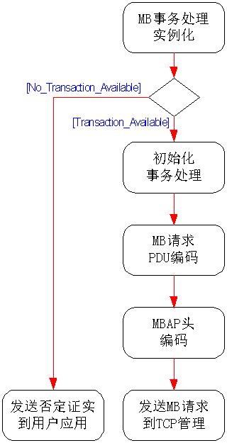
Picture12: Request generation operation diagram
Below are examples provided: From the address to05The remote server reads one wordMODBUSRequestADUcoding
- MODBUSRequestADUcoding:
| Instructions | size | example | |
| MBAPMessage header | transaction ID Hi | 1 | 0x15 |
| transaction ID Lo | 1 | 0x01 | |
| Protocol Identifier | 2 | 0x0000 | |
| Length | 2 | 0x0006 | |
| Unit identifier | 1 | 0xFF | |
| MODBUSRequest | function code (*) | 1 | 0x03 |
| starting address | 2 | 0x0005 | |
| number of registers | 2 | 0x0001 |
(*) SeeMODBUSProtocol specifications[2]
- transaction ID
Transaction identifiers are used to establish a connection between requests and future responses. ThereforeYes, that's rightTCPIn terms of connectivity, At the same time, This identifier must be unique. There are several ways to use this identifier:
- for example: Can be used as a simple device with a counter“TCPserial number”, Increase the counter at each request;
- It can also be used as an intelligent index or pointer, To identify the content of transaction processing, In order to remember the current remote server and unprocessed requests.
Usually, inMODBUSOn the serial link, The client must send one request at a time. This means that the client must wait for a response to the first request before sending the second requestInMODBUS TCPUp,Multiple requests can be sent to the same server without waiting for confirmation from the server. MODBUS/TCPtoMODBUSThe gateway between serial links is responsible for ensuring compatibility between these two operations.
The number of requests received by the server depends on its capacity, namely:The amount of server resources andTCPWindow Size. also, The number of transactions initiated simultaneously by the client also depends on the client's resource capacity. This implementation parameter is called“NnmberMaxofClientTransaction”, Must act asMODBUSDescribe a feature of the client. According to the type of device, The value of this parameter is1~16.
- Unit identifier
inMODBUSorMODBUS+When addressing devices in a serial link subnet, This domain is used for routing purposes. under these circumstances, “Unit Identifier”Carrying a remote deviceMODBUSslave address:
- IfMODBUSServer connection toMODBUS+orMODBUSSerial Link Subnet, And configure the address of this server through a bridge or gateway, MODBUSUnit identifiers are necessary for identifying slave devices connected to a bridge or gateway in a subnet. PurposeIPThe address recognizes the address of the bridge itself, And the bridge usesMODBUSUnit identifier forwards the request to the correct slave device.
- Allocate on the serial linkMODBUSThe address of the slave device is1~247 (10numeral system) , Address 0 as broadcast address.
CorrectTCP/IPSpeaking of, UtilizeIPAddress AddressingMODBUSServer; Therefore, MODBUSUnit identifiers are useless. Required Value0xFF.
- When directly connected toTCP/IPOn the internetMODBUSWhen addressing servers, Suggest not to“Unit identifier”Effective domain usageMODBUSslave address. Reassignment in an automated systemIPIn the case of an address, And if previously assigned toMODBUSserver'sIPThe address is assigned to the gateway again, Using a valid slave address may cause trouble due to poor routing of the gateway. Using an invalid slave address, The gateway is simply abandonedMODBUD PDU, And there won't be any problems. Suggestion: In adopting0xFFas“Unit identifier”Invalid value for.
Note:0It can also be used in conjunction withMODBUS/TCPDirect communication between devices.
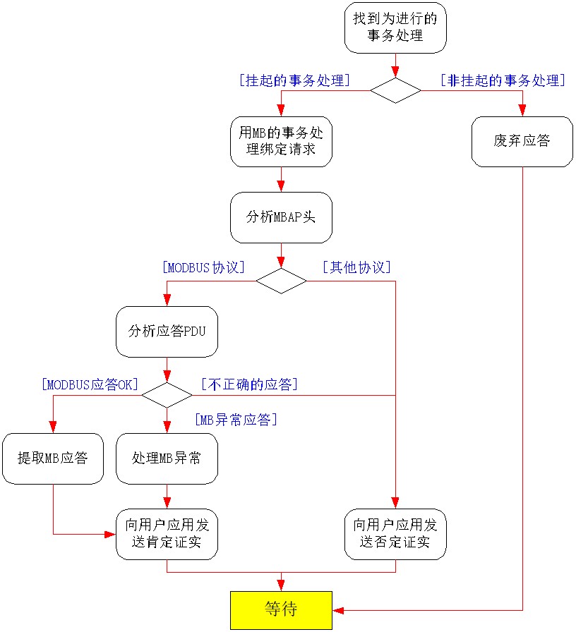
ProcessingMODBUSconfirm
inTCPConnecting in progress, When receiving a response frame, located inMBAPThe transaction identifier in the message header is used to match the response with the previously sent oneTCPConnect the original requests of the connection:
- If the transaction identifier does not mention any unresolved transactions, So the response must be abandoned;
- If the transaction identifier mentions unresolved transactions, So the response must be decomposed, In order to send to the user applicationMODBUSconfirm (Affirmative or negative confirmation) ;
Decomposing response is testingMBAPMessage header andMODBUS PDUThe response:
- MBAPMessage header
The verification protocol identifier must be0x0000in the future, The length is givenMODBUSResponse size.
If the response comes from a direct connection toTCP/IPnetworkMODBUSserver equipment, TCPThe connection identification code is sufficient to clearly identify the remote server. Therefore, MBAPThe unit identifier carried in the header is invalid, This unit identifier must be discarded.
If the remote server is connected to a serial link subnet, And respond from a bridge, Routing or gateway, So the unit identifier(Value)≠0xFF) Identify the remote end that sent the initial responseMODBUSServer.
- MODBUSResponsePDU
Function code must be verified, according toMODBUSagreement, AnalyzeMODBUSResponse format:
- If the function code is the same as the function code used in the request, And if the format of the response is correct, then, Send to user applicationsMODBUSResponse as affirmative confirmation.
- If the function code is aMODBUSException Code (function code+80H) , Send an abnormal response to the user application as positive confirmation.
- If the function code is different from the one used in the request (= Unexpected function codes) , Or if the format of the response is incorrect, then, Send an error signal to the user application as a negative confirmation.
Note:Positive confirmation refers to the confirmation that the server receives the request command and responds accordingly. It does not mean that the server can successfully complete the operation required in the request command (MODBUSAbnormal response indicates that the operation has failed to execute) .
Figure below17More in-depth description of the verification process.
Picture13: MODBUSConfirmation processing operation diagram
timeout management
CorrectMODBUS/TCPThe response time required for transaction processing is intentionally not specified.
This is because: From millisecond levelI/OScan to a long-distance wireless link with a delay of a few seconds, ExpectationMODBUS/TCPWill be used in the widest possible communication scenarios.
From the perspective of the client, Timeout must take into account the expected transmission delay on the network, In order to determine a reasonable response time. This transmission delay may be a few milliseconds in switched Ethernet, Or a few hundred milliseconds in a wide area network connection.
On the other hand, speaking in reverse, The timeout period for any client to start an application and retry should be greater than the expected maximum reasonable response time. If this is not followed, There is a potential danger of overcrowding on the target device or network, And conversely, it will lead to more errors. This is a feature that should always be avoided.
Therefore, in practice, The client timeout used in high-performance applications always seems to be related to network topology and expected client performance.
Systems where time is not a significant factor are often usedTCPDefault value as timeout value, On most platforms, A communication malfunction will be reported in a few seconds.
MODBUSserver-side
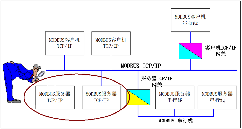
Picture14: MODBUSserver-side
MODBUSThe role of a server is to provide access to application objects and services to remote clients.
According to user applications, Provide different types of access:
- Simple Access: Obtain or set the properties of the application object;
- Advanced Access: Launch a specific application service
MODBUSThe server must:
- Map an application object to be readable or writableMODBUSobject, In order to obtain or set the properties of the application object;
- Provide a method for starting services on application objects;
During operation, MODBUSThe server must analyze the received dataMODBUSRequest, Process the required operations, ReturnMODBUSResponse.
MODBUSServer Design
MODBUSThe server design depends on the following two aspects:
- Types of access to application objects (Simple access to attributes or advanced access to services) ;
- MODBUSTypes of interaction between servers and user applications (Synchronous or asynchronous) .
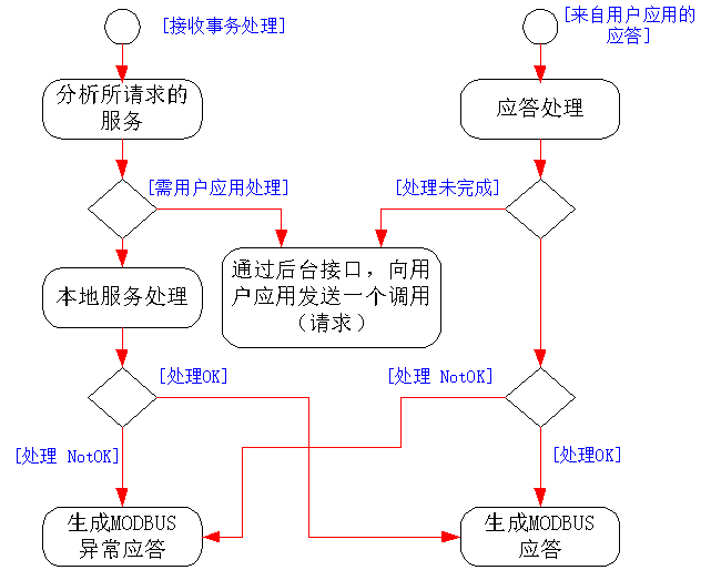
The following figure describes the main processing procedures carried out by the server, In order to obtain information fromTCPmanagementMODBUSRequest, then, Analyze request, Process the required operations, ReturnMODBUSResponse.
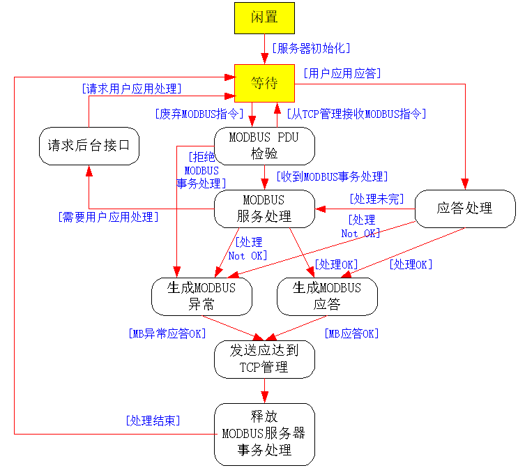
Picture15: ProcessingMODBUSInstruction operation diagram
As shown in the previous operation diagram:
- MODBUSThe server itself can immediately handle some services, No interaction with user applications;
- Some services may also require significant interaction with the processed user applications;
- Some advanced services require calling specific interfaces, namely:MODBUSbackground service. for example: Possible based on user application layer protocol, Use severalMODBUSInitiate user application services based on the timing of request/response transaction processing. The backend service is responsible for all individual tasksMODBUSProper handling of transactions, To facilitate the execution of global user application services.
Provide more complete descriptions in the following chapters.
MODBUSThe server can receive and simultaneously serve multipleMODBUSRequest to provide services. The server can receive at the same timeMODBUSThe maximum number of requests isMODBUSOne of the main features of a server. This quantity depends on the design of the server and its processing and storage capabilities. Call this implementation parameter“NumberMaxOfServerTransaction”, Must act asMODBUSA feature of the server describes this implementation parameter. According to the capabilities of the equipment, Its value range is: 1~16, .
“NumberMaxOfServerTransaction”Parameter pairsMODBUSThe operation and performance of servers have a significant impact. Especially important is, Managed concurrencyMODBUSThe number of transactions processed may affect the server's performanceMODBUSResponse time for requests.
MODBUS PDUinspection
The following diagram describesMODBUS PDUInspection operation.
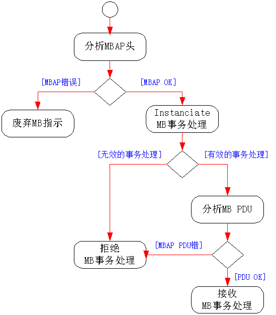
Picture16: MODBUS PDUInspection operation flowchart
MODBUS PDUThe inspection function is first decomposedMBAPMessage header. Protocol identifier field must be verified:
- If andMODBUSDifferent types of protocols, So abolish this directive.
- If it is correct (= MODBUSProtocol Type; value0x00) , Immediately give an example to illustrate oneMODBUSTransaction Processing.
A server can be explained by distanceMODBUSThe maximum number of transactions processed is determined by the parameter“NumberMaxOfTransaction” (System or configuration parameters) To define.
In the case of invalid transaction processing, The server generates aMODBUSException Response (Exception Code6: Server busy) .
If transaction processing is effective, It will be activated, In order to store the following information:
- Used for sending instructionsTCPConnection identifier(From)TCPManagement provides)
- MODBUSTransaction ProcessingID (MBAPGiven in the message header)
- Unit identifier (MBAPGiven in the message header)
then, decomposeMODBUS PDU. Firstly, analyze the function code:
- When invalid, GenerateMODBUSException Response (Exception Code1: invalid function)
- If receiving function codes, Start a server“MODBUSService processing”Operation.
MODBUSService processing
Picture17: MODBUS Service processing operation flowchart
Based on the device software and hardware structure in the following examples, Requirements can be made in different waysMODBUSService processing:
- Within a small device or single threaded architecture, MODBUSThe server can directly access user application data, The server itself can handle the requested services locally, Without the need to call backend services.
according to“MODBUSProtocol specifications”, Perform this processing. In the event of an error, GenerateMODBUSException Response.
- In a modular multiprocessor device or multi-threaded architecture, “Communication Layer”and“User application layer”They are two independent entities, Communication entities can fully handle some unimportant services, And other services require coordination between application backend services and user application entities to complete.
In order to achieve interaction with user applications, MODBUSThe backend service must implement all appropriate mechanisms, In order to handle transaction processing of user applications, And correctly manage user application calls and corresponding responses.
User Application Interface (Backend interface)
inMODBUSIn the backend service, Several strategies can be implemented to complete the work, Although from the perspective of user network throughput, Interface bandwidth usage, response time, Even from the perspective of design workload, These strategies are unbalanced.
MODBUSThe backend service will adopt appropriate interfaces for user applications:
- Or physical interfaces based on serial links, Or dual portRAMPlan, Or a simple oneI/OCable, Or a logical interface based on message transmission services provided by the operating system.
- The interface to the user application can be synchronous or asynchronous.
MODBUSThe backend service will also use appropriate design patterns to obtain/set target attributes or trigger services. In some cases, a simple“Gateway Pattern”It will be enough. In other cases, From simple exchange table history to more complex repetition mechanisms, Designers will have to implement caching strategies“Proxy server mode”, .
MODBUSThe backend service is responsible for implementing protocol conversion, In order to interact with user applications. Therefore, It must have mechanisms to achieve message splitting and reassembly, Data consistency assurance and all necessary synchronization functions.
MODBUSGeneration of response
Once the request is processed, MODBUSThe server must use appropriateMODBUSServer transaction generates a response, And the response must be sent toTCPManage Components.
According to the processing results, Can generate two types of responses:
- affirmativeMODBUSResponse:
- Response function code = Request function code
- MODBUSException Response:
- The purpose is to provide the client with information related to errors detected during the processing
- Response function code = Request function code+0x80
- Provide exception codes to indicate the cause of the error.
| Exception Code | MODBUSName | Remark |
| 01 | Illegal function codes | The server is not familiar with the function code |
| 02 | Illegal data address | Related to the request |
| 03 | Illegal data values | Related to the request |
| 04 | Server malfunction | During the execution process, Server malfunction |
| 05 | Confirm | The server accepts service calls, But it takes a relatively long time to complete the service. Therefore, The server only returns a confirmation of receiving one service call. |
| 06 | Server busy | The server cannot acceptMODBUSRequestPDU. Customer applications are responsible for deciding whether and when to resend requests. |
| 0A | Gateway failure | The gateway route is invalid. |
| 0B | Gateway failure | The target device is not responding. Gateway generates this exception message. |
MODBUSResponsePDUMust beMBAPAdd a prefix to the message header, Generate data from transaction processing bodyMBAPMessage header.
- Unit identifier
When receivedMODBUSWhen the unit identifier is provided in the request, Copy this unit identifier, And store it in the body of the transaction processing.
- Length
Server ComputingMODBUS PDUAnd the size of the unit identifier wordIn“Length”Set this value in the domain.
- Protocol Identifier
Set the protocol identifier field to0x0000 (MODBUSagreement) , In the receivedMODBUSProvide the protocol identifier in the request.
- transaction ID
Set this domain as“transaction ID ”Value,It is related to the initial request, And store it in.
Utilize the transaction processing stored in the main textTCPConnect correctlyMODBUSClient returnMODBUSResponse. When sending a response, The transaction processing text must be left blank.
Implementation Guide
The purpose of this chapter is to propose an example of implementing message transmission services. The model described below can be implemented as a client or serverMODBUSGuidelines for Message Transmission Service Process.
Object Model Diagram

Picture18: MODBUSSchematic diagram of message transmission service object model
Schematic diagram of the object model composed of four main program packages:
- Configuration layer, It configures and manages the operational modes of other package components
- TCPManagement, It makesTCP/IPStack and ManagementTCPConnected communication application layer connection. This refers to the management of socket interfaces.
- Communication application layer, It is located on one sideMODBUSClient and on the other sideMODBUSServer composition. The package and user application link.
- User application, It corresponds to the device application, It is completely related to the device, Therefore, it will not be discussed in this document.
This model is independent of the choice of implementation, for example: OSType, Storage management, etc. To ensure this lack of relevance, inTCPUse a common interface layer between the management layer and the communication layer, as well as between the communication layer and the user application layer (generic Interface layers) .
There are different implementation methods to implement this interface: Transmission between two tasks, Shared Memory, Serial Link Interface, Process call, etc.
To define the following implementation model, Made some assumptions:
- Static memory management
- Synchronization processing of servers
- Handle tasks related to all socket receptions.
TCPManagement package
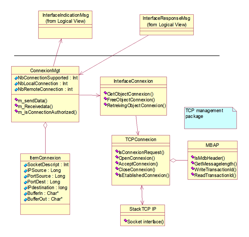
Picture19: MODBUS TCPManagement package
TCPThe management package includes the following categories:
ClnterfaceConnexion: The purpose of this class is to manage the repository used for connections.
CltemConnexion: This class contains all the information needed to describe the connection.
CTCPConnexion: This category provides automatic managementTCPConnection method (CStackTCP_IPProvide interface sockets) .
CconnexionMngt: This category manages all connections, and pass throughCinterfaceindicationMsgandCinterfaceRoseponseMsgto, toward, at, facingMODBUSServer/MODBUSClient sends request/response. This class also handles access control for connection establishment.
CMBAP: This category provides read/write/analysis servicesMODBUS MBAPThe method.
CStackTCP_IP: This class executes socket services and provides stack parameter configuration.
Configuration layer package
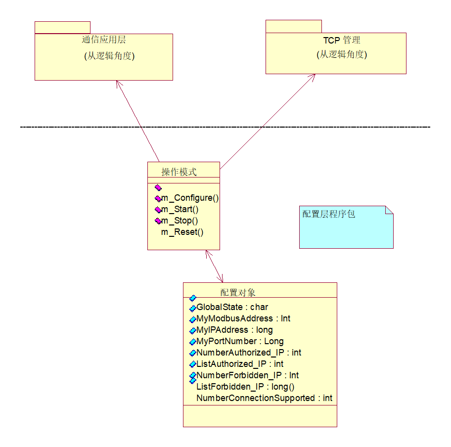
Picture20: MODBUSConfiguration layer package
The configuration layer package includes the following classes:
TConfigreObject: This class groups the data required for configuring each component together. UseCoperatingModeWithin the classm_ConfireMethod to fill this structure. Each class that needs to be configured retrieves its own data from this object. The configuration data is related to the implementation itself. Therefore, Provide the attribute table of this class as an instance.
CoperatingMode: The function of this class is to fillTConfigueObject (According to the user's configuration) Manage the operating modes of the following categories.
- CMODBUSServer
- CMODBUSClient
- CconnexionMngt
Communication layer package
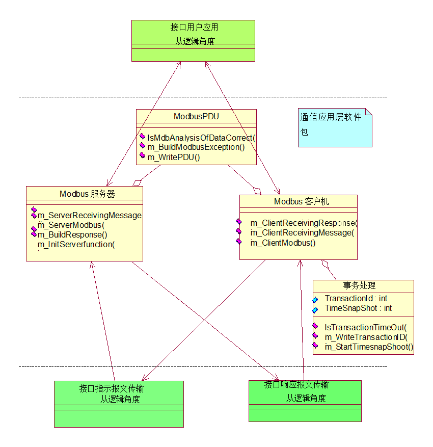
Picture21: MODBUSCommunication application layer package
The communication application layer package includes the following categories:
CMODBUSServer: FromCinterfaceIndicationMsgReceived in the middleMODBUSinquire (Throughm_ServerRecievingMessagemethod) . The purpose of this category is to establish based on inquiriesMODBUSResponse orMODBUSabnormality (Entering from the internet) . This type of implementationMODBUSserver'sGraph State. Only classCoperatingModeSent user configuration and correct operating mode, Only then can a response be generated.
CMODBUSClient: From ClassCinterfaceUserApplicationRead from the middleMODBUSinquire, The task of the client is to usem_ClientReceivingMessageMethod for receiving inquiries. This type of implementationMODBUSThe client'sState Graph, And manage the transaction processing of links with responsive queries (From the internet) . Only classCoperatingModeSent user configuration and correct operating mode, Only then can inquiries be sent through the network.
CTransaction: The method and structure for implementing management transactions in this class.
interface class
CInterfaceUserApplication: This class represents the interface with user applications, It provides two methods for accessing user data. In practical implementation, Based on the capabilities of hardware and software devices, Implement this method in different ways (Equivalent to a terminal driver, visitPCMCIAExamples of, Shared storage, etc) .
CInterfaceIndicationMsg: This interface class is used to connect from the network toMODBUSServer sends inquiry, And sending responses from the network to the client. This category makesTCPManagementConnect with communication application layer packages (From the internet) . The implementation of this class is related to the network.
CInterfaceResponseMsg: This interface class is used to receive responses from the server, And sending queries from the client to the network. This class enables communication application layer packages andTCPManagementConnect (Towards the Network) . The implementation of this class is related to the device.
Schematic diagram of communication implementation classes
The schematic diagram of the following classes is a complete implementation scheme.
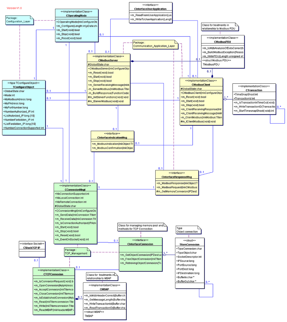
Picture22: Schematic diagram of the class
Sequence diagram
Two sequence diagrams are described below, To illustrate the client machineMODBUSTransaction processing and serversMODBUSTransaction Processing.
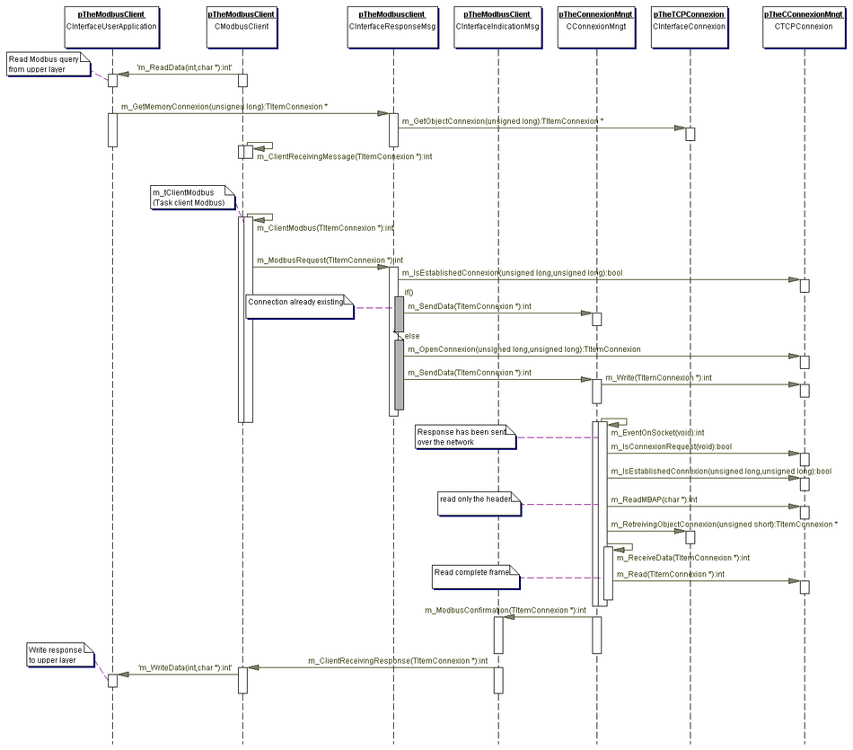
Picture23: MODBUSClient sequence diagram
To better understand the client sequence diagram, A simple annotation is:
First step: Read inquiries from user applications (viam_Readmethod).
Step two: The task of the client is to receiveMODBUSinquire (Throughm_ClientReceivingMessagemethod) . This is the entry point for the client machine. In order to coordinate inquiries and corresponding responses, When asked, Client uses transaction processing resources (class name: CTransaction) . Through call type interfacesCInterfaceResponseMsgto, toward, at, facingTCP_ManagementsendMODBUSinquire (Throughm_MODBUSRequestmethod) .
Step Three: If a connection has already been established, And there's no need to do anything about the connection, So send messages through the network. otherwise, Before sending messages on the network, There must be an open connection.
at this moment, The client is waiting for the final discussion response (From remote server) .
Step Four: If a response has already been received from the network, thenTCP/IPStack receiving data (Secretly callm_EventOnStackmethod) .
If a connection has been established, So read itMBAPTo restore the connected object (Connect objects to provide storage resources and other information) .
Read data from the network, Through class interfacesCinterfaceIndicationMsgSend confirmation to the client (Throughm_MODBUSConfirmationmethod) . The task of the client is to receiveMODBUSconfirm (Throughm_ClientReceivingResponsemethod) .
Finally, Write a response to the user application (Throughm_Writedatamethod) , And the transaction processing resources are idle.
Below isMODBUSExamples of server exchange:
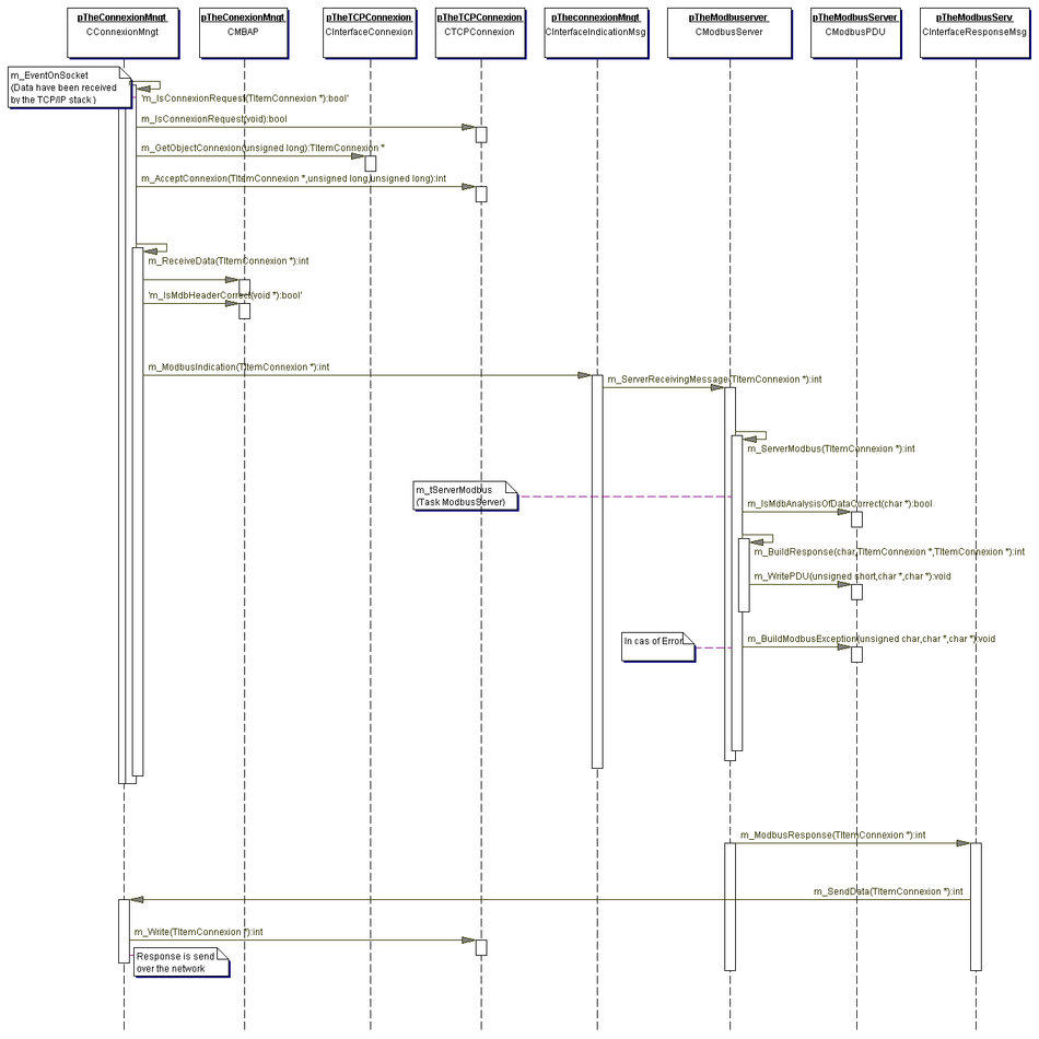
Picture24: MODBUSServer Sequence Diagram
To better understand the client sequence diagram, A simple annotation is:
First step: A certain client has sent an inquiry through the network (MODBUSinquire) . TCP/IPStack receiving data (Secretly callm_EventOnSocketmethod) .
Step two: The request may be a connection request, It may not be a connection request either (Throughm_IsConnexionRequestmethod) . If the request is a connection request, So allocate connection objects and send/receiveMODBUSBuffer for frames (m_GetObjectConnexion) . afterwards, Must check and accept connection access control.
Step Three: If the inquiry isMODBUSRequest, So we can read out the completeMODBUS Query (Throughm_ReceiveDatamethod) . at this moment, Must analyzeMBAP (Throughm_IsMdbHeadercorrectmethod) . ThroughCInterfaceIndicationMessagingClass directed server task (task) Send complete frames (Throughm_MODBUSIndicationmethod) . The task of the server is to receiveMODBUS QUERY (Throughm_ServerReceivingMessagemethod) And analyze it.
If any errors occur (Unsupported function codes, etc) , GenerateMODBUSAbnormal frame shape (m_BuildMODBUSException) , Otherwise, generate a response.
Step Four: ThroughCInterfaceResponseMessaging (Throughm_MODBUSResponsemethod) Send a response online. Throughm_SendDataMethod for handling connected objects (Restore connection descriptors, etc) , Sending data over the network.
Description of Classes and Methods
MODBUSServer side classes
class name: CMODBUSServer
class name: CMODBUSServer
Stereotypeimplementation class
Provide server mode managementMODBUSMethod of message transmission
| Domain Overview | |
| protected char | GlobalStateMODBUSThe status of the server |
| Overview of Constructors | |
| CMODBUSServer(TConfigureObject * lnkConfigureObject)constructor: Generate internal objects | |
| Method Overview | |
| protected void | m_InitServerFunctions(void )To fill the functional array“m_ServerFunction”The function of calling the sequence constructor |
| bool | m_Reset(void )Method for resetting the server, If reset, So return a positive value |
| int | m_ServerReceivingMessage(TItemConnexion * lnkMODBUS)andCindicationMsg: : m_MODBUSIndicationThe interface, To receive inquiries from the network, If there are any issues, Return negative value |
| bool | m_Start(void )Method to start the server, If activated, Return positive value |
| bool | m_Stop(void )Method to stop the server, If stopped, Return positive value |
| protected void | m_tServerMODBUS(void )server'sMODBUSTask.. |
MODBUSClient class
class name: CMODBUSClient
class name: CMODBUSClient
Provide client mode managementMODBUSMethod of message transmission
Stereotypeimplementation class
| Domain Overview | |
| protected char | GlobalStateMODBUSThe status of the client machine |
| Overview of Constructors | |
| CMODBUSClient(TConfigureObject * lnkConfigureObject)constructor: Generate internal objects, Start 0 variable | |
| Method Overview | |
| Int | m_ClientReceivingMessage(TItemConnexion * lnkMODBUS)Interface for receiving message transmission from the application layer: Call to read data callCinterfaceUserApplication::m_Read Obtaining memory for transaction processingCInterfaceConnexion::m_GetObjectConnexion If there is a problem, So return a negative value |
| Bool | m_Reset(Method for resetting components (empty), If reset, Return positive value |
| bool | m_Start(The method of starting an empty component, If activated, Return positive value |
| bool | m_Stop(The method of stopping an empty component, If stopped, Return positive value |
| protected empty | m_tClientMODBUS(Empty client'sMODBUSTask.... |
Class of interfaces
Interface indicator class
class name: CInterfaceIndicationMsg
Directly known subclasses
class name: CInterfaceIndicationMsg
fromTCP_Managementto, toward, at, facingMODBUSThe class of messages sent by servers or clients
Stereotypeinterface
| Method Overview | |
| int | m_MODBUSConfirmation(TItemConnexion * lnkObject)Method for receiving incoming responses and calling clients: By using available reference values, Message queuing, Remote process calls, etc, ... |
| int | m_MODBUSIndication(TItemConnexion * lnkObject)Read inMODBUSMethods for querying and calling servers: By using available reference values, Message queuing, Remote process calls, etc, ... |
Interface response class
class name: CInterfaceResponseMsg
Directly known subclasses:
class CInterfaceResponseMsg
From the client or server toTCP_ManagementClass for sending responses or inquiries
Stereotypeinterface
| Method Overview | |
| TitemConnexion * | m_GetMemoryConnexion(unsigned long IPDest)Retrieve objects from the repositoryItemConnexion, If there is insufficient storage, return value-1 |
| int | m_MODBUSRequest(TItemConnexion * lnkCMODBUS)Will enterMODBUSAsk the client to writeConnexionMngtThe method: By using available reference values, Message queuing, Remote process calls, etc, ... |
| int | m_MODBUSResponse(TItemConnexion * lnkObject)TranslateMODBUSServer response writingConnexionMngtThe method: By using available reference values, Message queuing, Remote process calls, etc, ... |
Connection management category
class name: CConnexionMngt
class name: CConnexionMngt
Manage allTCPConnected classes
Stereotype implementation class
| Domain Overview | |
| protected char | GlobalStateComponentConnexionMngtThe comprehensive state |
| Int | NbConnectionSupportedThe total number of connections |
| Int | NbLocalConnectionThe number of connections opened from local clients to remote servers |
| Int | NbRemoteConnectionThe number of connections opened from remote clients to local servers |
| Overview of Constructors | |
| CconnexionMngt(TConfigureObject * lnkConfigureObject)constructor: Generate internal objects, Start 0 variable | |
| Method Overview | |
| int | m_EventOnSocket(Empty wake-up |
| bool | m_IsConnectionAuthorized(unsigned long IPAdress)If authorizing a new connection, Return positive value |
| int | m_ReceiveData(TItemConnexion * lnkConnexion)andCTCPConnexion::writeinterface, The method of reading data from the network, If there is a problem, Return negative value |
| bool | m_Reset(Empty) ResetConnectionMngtMethod of Components, If reset, Return positive value |
| int | m_SendData(TItemConnexion * lnkConnexion)forCTCPConnexion::readinterface, Method of sending data to the network, If there is a problem, Return negative value |
| bool | m_Start(Empty startupConnectionMngtMethod of Components, If activated, Return positive value |
| bool | m_Stop(The method of stopping an empty component, If stopped, Return positive value |


Leave a Reply