1. Introduction
In the rapidly evolving Industry 4.0 era, edge computing has emerged as a pivotal technology. It enables data processing to be situated closer to the source of the data, thereby enhancing processing speed and reducing response time. This technology demonstrates immense potential in the field of industrial automation, as it effectively processes vast amounts of data from industrial devices and sensors, facilitating real-time monitoring and control.
As a bridge connecting sensors, controllers, and central processing systems, edge gateways are responsible not only for data acquisition and preprocessing but also for data encryption and transmission, ensuring the security and integrity of data during transmission. Furthermore, edge gateways support multiple communication protocols, including but not limited to RS485 and Ethernet, making them widely applicable in various industrial environments.
2. Overview of Edge Gateways
2.1 Definition and Functions
An edge gateway is a device situated between the data generation source (such as sensors) and the central data processing facility (such as a cloud server). Its primary functions include data acquisition, preprocessing, storage, and forwarding. By processing data locally, edge gateways can reduce the demand for data transmission to central servers, lower latency, enhance data processing efficiency, and maintain continuous system operation in poor network conditions.
2.2 Differences between Edge Gateways and Traditional Gateways
Compared to traditional gateways, edge gateways exhibit significant improvements in processing power and intelligence. Traditional gateways typically handle data forwarding only, whereas edge gateways are equipped with enhanced computing capabilities, enabling them to perform complex data analysis and processing tasks. Additionally, edge gateways often integrate additional security measures, such as data encryption and firewalls, to ensure data security during transmission.
By introducing edge gateways, enterprises can effectively address issues such as slow data processing, long system response times, and data security concerns. This is of great significance for achieving efficient industrial automation and smart manufacturing. With technological advancements and increasing application demands, the role and functionality of edge gateways will continue to evolve, bringing more possibilities and challenges to industrial automation.
Recently, the Changwei Tongda EN6400 edge gateway was utilized in a project. Next, I will present the application and technical details of this edge gateway through a case study from real-world business operations.
3. Technical specifications and features of Changwei Tongda EN6400 gateway
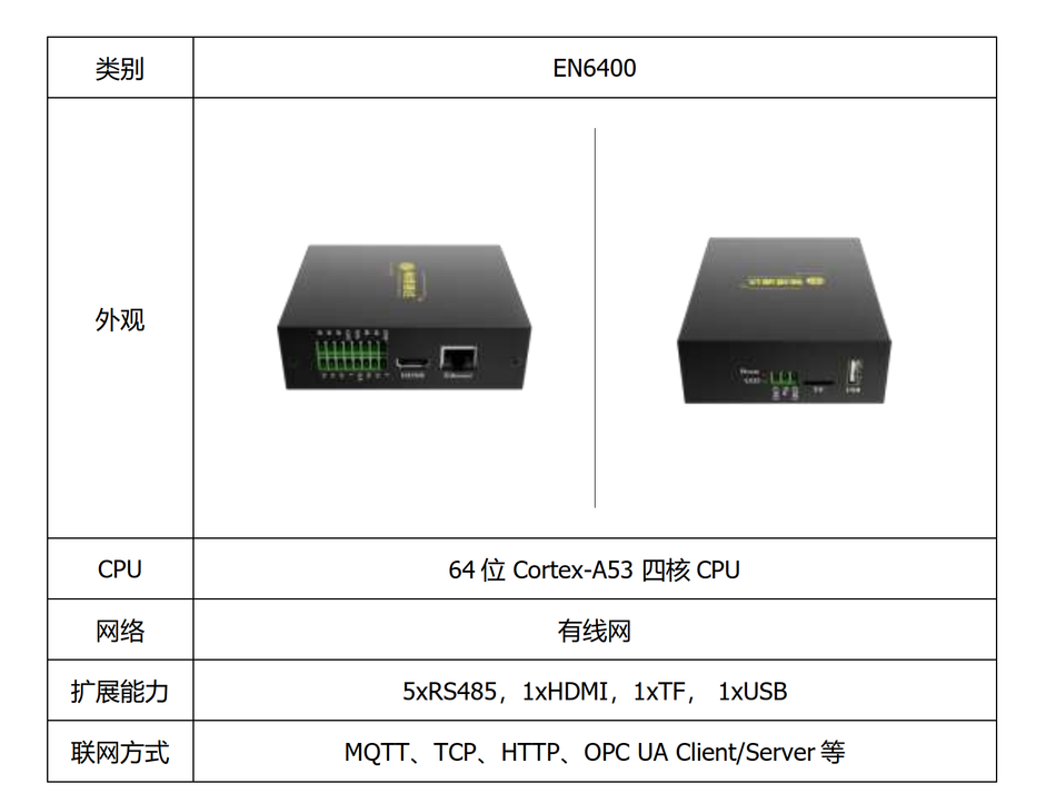
Before use, let's take a look at the detailed technical specifications and parameters of this gateway
- With ARM as the core, it achieves a balanced performance in power consumption, computing power, size, and thermal performance.
- The input power supply has a wide voltage range and is equipped with anti-reverse connection protection.
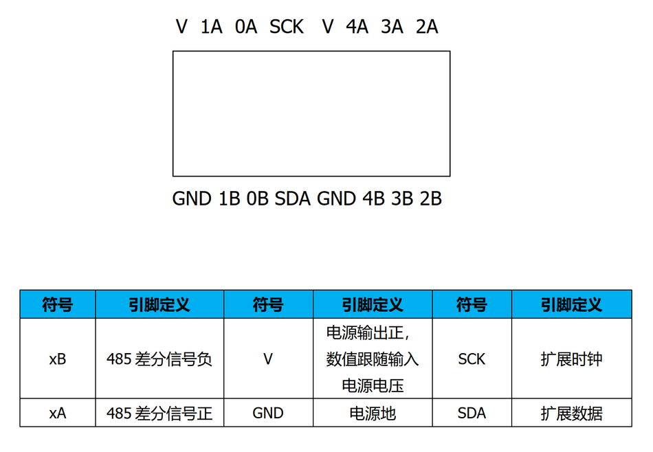
- It features 5 independent 485 interfaces, supporting the connection of Modbus devices.
- It has 1 HDMI output for easy connection to a monitor.
- 1 USB 2.0 port, allowing for external connection of keyboards, mice, and USB drives.
- 1 TF card slot for expanding data storage space.
- It supports wired Ethernet for convenient deployment.
- The interface adopts spring-type terminals, facilitating manual plugging and unplugging of wiring harnesses.
- The metal shell has a protection level of IP30, being sturdy, lightweight, and corrosion-resistant, with an optional DIN buckle for easy rail installation.
Communication interfaces
In the EN6400 gateway, there is built-in Node-RED, and other platforms can also be embedded. Specific details can be seen in the image below, and it is set to start automatically at boot. The gateway's default LAN IP is 192.168.0.202.
4. Practical projects
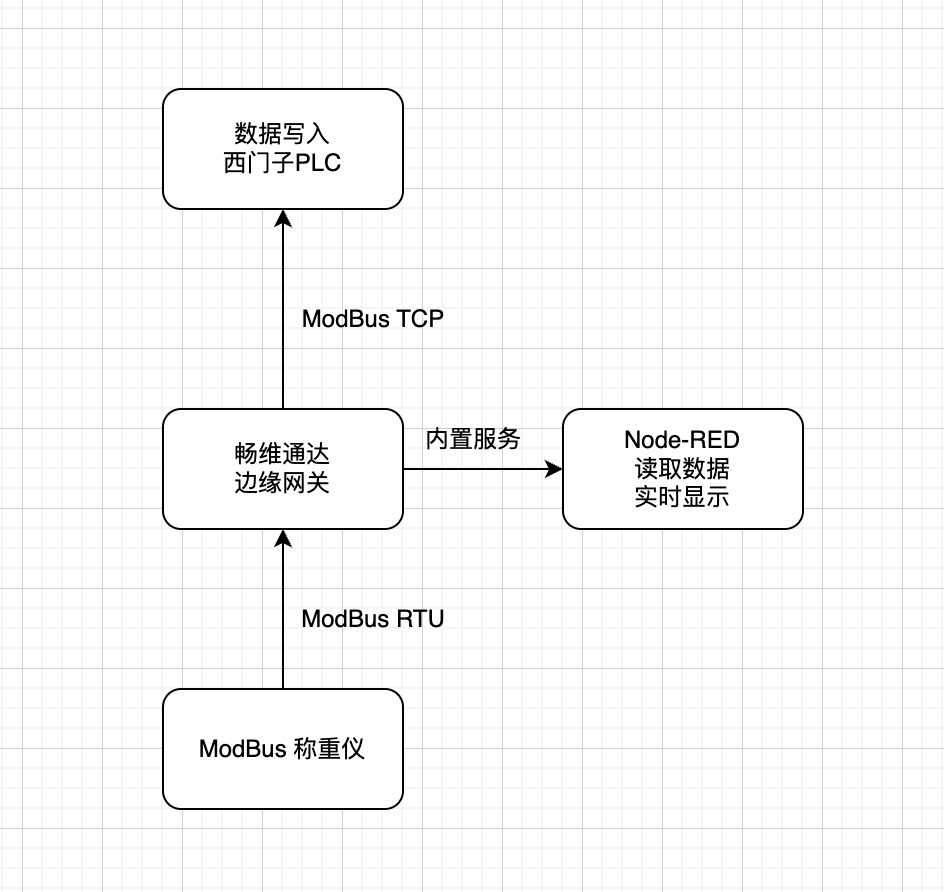
Due to the limited hardware equipment available, I designed a practical test using an edge gateway to collect data from weighing scales via RS485, read serial port data through the built-in Node-RED of the edge gateway, and display it using a dashboard node. Finally, the data was written to a Siemens PLC via Modbus TCP. The main focus was on testing the advantages of the edge gateway in practical projects.
The overall architecture is as follows
4.1 Using EN6400 to collect RS485 sensor data
The weighing scales and the edge gateway communicate using Modbus RTU through the built-in 5 RS485 interfaces, specifically 0A and 0B, for collecting weight data from the scales. The gateway acts as the Modbus master, while the scales are slaves with a slave address of 2, a baud rate of 19200, 8 data bits, 1 stop bit, and no parity.
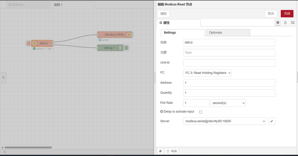
The node used in Node-RED is a Modbus node, which reads device data once per second.
The following diagram shows the flow file connections and node configuration.
Printed output.
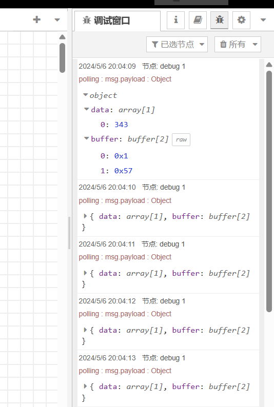
The number 343 represents 3.43KG.
Complete flow content.
[
  {
    "id": "bf7de48e301a2645",
    "type": "tab",
    "label": "拿我格子衫来",
    "disabled": false,
    "info": "",
    "env": []
  },
  {
    "id": "df0b29fd65548aeb",
    "type": "modbus-read",
    "z": "bf7de48e301a2645",
    "name": "485-0",
    "topic": "",
    "showStatusActivities": false,
    "logIOActivities": false,
    "showErrors": false,
    "showWarnings": true,
    "unitid": "",
    "dataType": "HoldingRegister",
    "adr": "1",
    "quantity": "1",
    "rate": "1",
    "rateUnit": "s",
    "delayOnStart": false,
    "startDelayTime": "",
    "server": "9f669d2b1c2d58e3",
    "useIOFile": false,
    "ioFile": "",
    "useIOForPayload": false,
    "emptyMsgOnFail": false,
    "x": 190,
    "y": 160,
    "wires": [
      [
        "a22b902052776c1d"
      ],
      [
        "ad51dea38739870b"
      ]
    ]
  },
  {
    "id": "a22b902052776c1d",
    "type": "modbus-write",
    "z": "bf7de48e301a2645",
    "name": "",
    "showStatusActivities": false,
    "showErrors": false,
    "showWarnings": true,
    "unitid": "",
    "dataType": "HoldingRegister",
    "adr": "0",
    "quantity": "1",
    "server": "97d630483ae5377e",
    "emptyMsgOnFail": false,
    "keepMsgProperties": false,
    "delayOnStart": false,
    "startDelayTime": "",
    "x": 520,
    "y": 120,
    "wires": [
      [],
      []
    ]
  },
  {
    "id": "ad51dea38739870b",
    "type": "debug",
    "z": "bf7de48e301a2645",
    "name": "debug 1",
    "active": true,
    "tosidebar": true,
    "console": false,
    "tostatus": false,
    "complete": "payload",
    "targetType": "msg",
    "statusVal": "",
    "statusType": "auto",
    "x": 500,
    "y": 180,
    "wires": []
  },
  {
    "id": "9f669d2b1c2d58e3",
    "type": "modbus-client",
    "name": "拿我格子衫来",
    "clienttype": "serial",
    "bufferCommands": true,
    "stateLogEnabled": false,
    "queueLogEnabled": false,
    "failureLogEnabled": true,
    "tcpHost": "127.0.0.1",
    "tcpPort": "502",
    "tcpType": "DEFAULT",
    "serialPort": "/dev/ttyS0",
    "serialType": "RTU",
    "serialBaudrate": "19200",
    "serialDatabits": "8",
    "serialStopbits": "1",
    "serialParity": "none",
    "serialConnectionDelay": "100",
    "serialAsciiResponseStartDelimiter": "0x3A",
    "unit_id": "2",
    "commandDelay": "1",
    "clientTimeout": "1000",
    "reconnectOnTimeout": true,
    "reconnectTimeout": "2000",
    "parallelUnitIdsAllowed": true,
    "showWarnings": true,
    "showLogs": true
  },
  {
    "id": "97d630483ae5377e",
    "type": "modbus-client",
    "name": "Fizz",
        "clienttype": "tcp",
        "bufferCommands": true,
        "stateLogEnabled": false,
        "queueLogEnabled": false,
        "failureLogEnabled": true,
        "tcpHost": "192.168.0.10",
        "tcpPort": "502",
        "tcpType": "DEFAULT",
        "serialPort": "/dev/ttyUSB",
        "serialType": "RTU-BUFFERD",
        "serialBaudrate": "9600",
        "serialDatabits": "8",
        "serialStopbits": "1",
        "serialParity": "none",
        "serialConnectionDelay": "100",
        "serialAsciiResponseStartDelimiter": "0x3A",
        "unit_id": 1,
        "commandDelay": 1,
        "clientTimeout": 1000,
        "reconnectOnTimeout": true,
        "reconnectTimeout": 2000,
        "parallelUnitIdsAllowed": true,
        "showWarnings": true,
        "showLogs": true
    }
]
4.2 Displaying charts using built-in Node-RED.
To display real-time data, it is necessary to install the dashboard. For those with poor network connectivity, you can set the npm source to Huawei or Taobao.
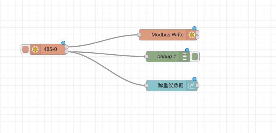
Complete flow connections
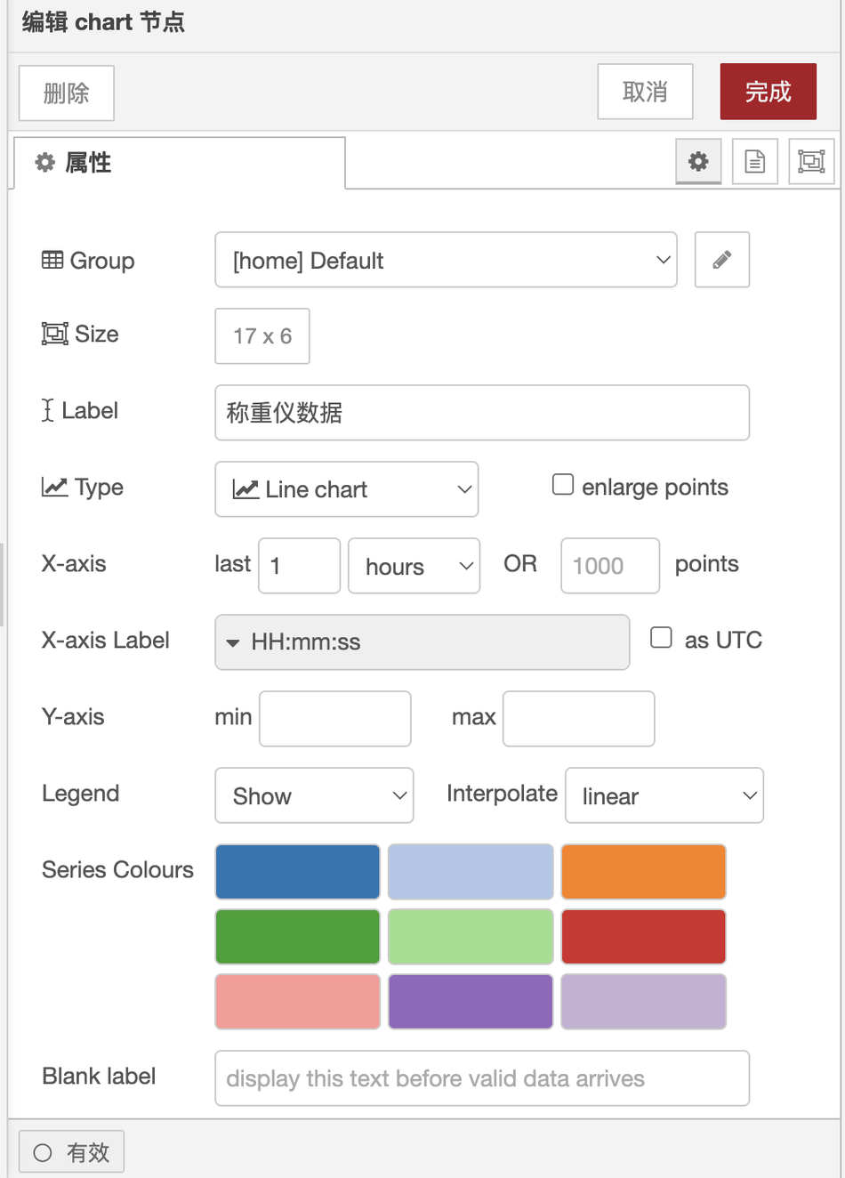
The configuration of the chart node is as follows:
The display effect of real-time data is shown in the following figure:
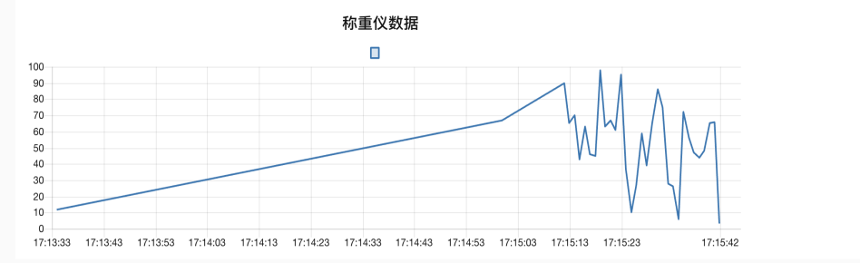
Random pressure is applied on the weighing instrument, and the data can be read in real-time on the Node-RED UI.
The default access address of the UI is: http://192.168.0.202:1880/ui
(Original link: https://fizzz.blog.csdn.net/article/details/138586861, reproduced with permission from the original authorPlease bring me my checkered shirtAgreed, all rights reserved)
4.3 Writing data into the PLC
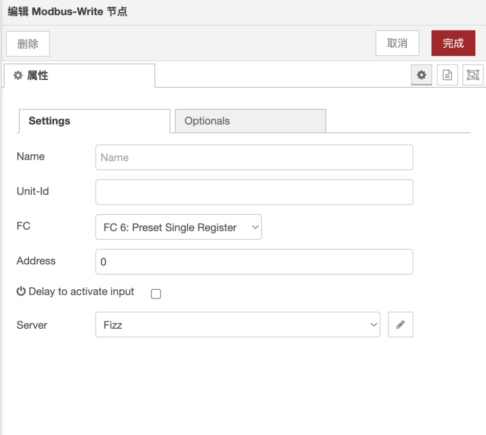
The Modbus Write node in Node-RED is used to write data into the Siemens PLC through the Modbus TCP protocol.
The configuration of the Modbus Write node is as follows
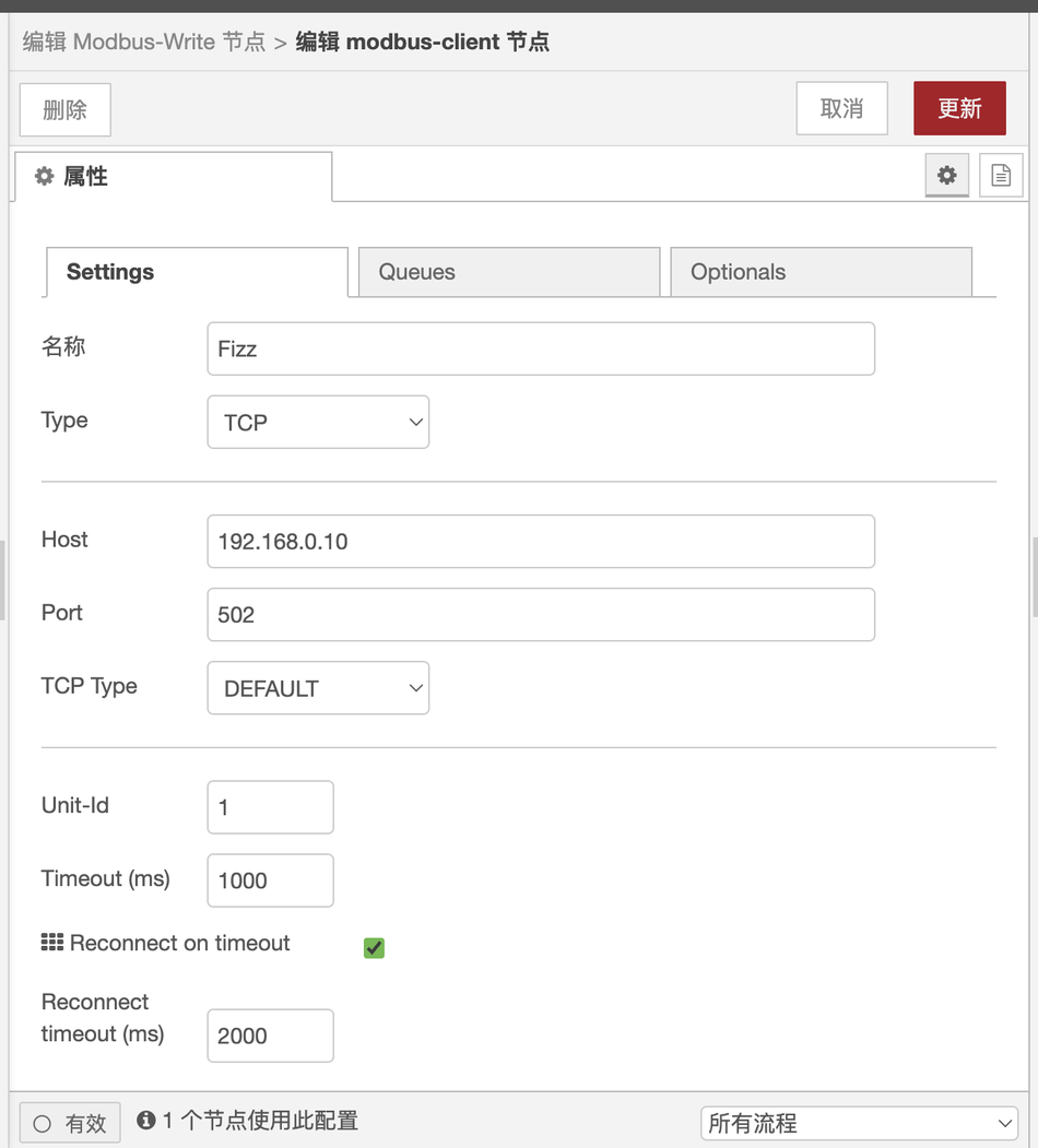
Modbus client node configuration
The data collected by the gateway is transmitted to the Siemens 200smart PLC,
The communication method involves the gateway acting as a Modbus TCP client, with the 200smart PLC acting as the server.
The VW0 register of the 200smart PLC is the Modbus TCP address 0.
After receiving data, the PLC VW0 processes it internally through a program and converts it into a real number to be stored in VD300.
Connect the gateway and the computer to the switch using a network cable, so that Modbus TCP communication can be performed within the local area network.
The PLC program is as follows:
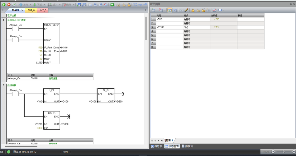
If you need the complete PLC program, feel free to send me a direct message (bring me my checkered shirt).
PLC program operation:
1. Open the programming software for the 200smart PLC: STEP 7-MicroWIN SMART.
2. Select the CPU model of the PLC and establish communication with the PLC.
3. Open the PLC program, import it, download it to the PLC, and start the PLC after the download is complete.
4. Click on the program monitoring and status chart monitoring of the PLC to monitor the program operation and PLC register data changes online.
5. Project summary
Overall, in practical project applications, the Changwei Tongda edge gateway performs exceptionally well. Whether it's the numerous Modbus interfaces or the auto-start Node-RED upon power-on, the user experience is very smooth. One thing to note is that since the default IP is 192.168.0.202, if the network segment set by the switch or router does not start with 192.168.0, the IP cannot be obtained. You need to modify the router or connect a keyboard and mouse to the gateway to modify its IP configuration file.


Leave a Reply