
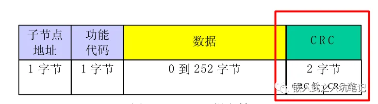
I have already analyzed the differences between RTU frames and ASCII frames, and observant friends should find that there is a common component - error checking - in both different message transmission modes. This error check is not different between RTU mode and ASCII mode.
See the comparison below: Error checking in RTU mode:
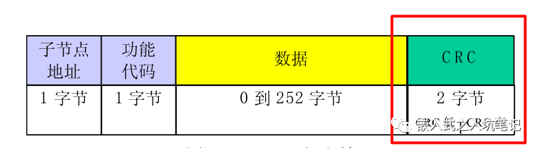
Error checking in ASCII mode:

In summary, CRC check is used in RTU mode, while LRC check is used in ASCII mode.
The following will explain how these two different verification methods are implemented.
1. CRC verification in RTU mode
Error checking domain based on cyclic redundancy checking (CRC) algorithm in RTU mode. CRC domain checks the content of the entire message. This check is performed regardless of whether the message has parity or not. CRC contains a 16 bit value consisting of two 8-bit bytes, which is attached as the last field of the message after the message. After calculation, the low byte is appended first, followed by the high byte. The CRC high byte is the last sub section of the message sent. The CRC value attached to the message is calculated by the sending device. The receiving device recalculates the CRC value when receiving the message and compares the calculated result with the actual received CRC value. If two values are not equal, it is an error. This operation can prevent errors from occurring during data transmission, leading to abnormal phenomena in the end.
(1) The principle of CRC generation
During the generation process of CRC, each 8-bit character is XORed with the value in the register. Then the result shifts (Shift) 1 bit towards the least significant bit (LSB) direction, while the most significant bit (MSB) position is charged to zero. Then extract and check the LSB: if LSB is 1, the value in the register is XORed with a fixed preset value; If LSB is 0, no XOR operation is performed.
This process will be repeated until 8 shifts are executed. After completing the last (8th) shift and related operations, the next 8-bit byte is XORed with the current value of the register, and then repeated 8 times as described above. The final value in the register obtained after all sub nodes in the message have been computed is the CRC.
(2) The generation process of CRC
1. Take one 16 Load the bit register into hexadecimal format FFFF (Full) 1). Call it CRC register.
2. Put the first one of the message 8 Bit bytes and 16 bit CRC Low byte XOR of registers,Result placed CRC register.
3. Translate CRC Register shift to the right 1 bit (To) LSB Direction), MSB Charge zero. Extract and detect LSB.
4. (If) LSB for 0): Repeat steps 3 (Another shift).(If) LSB for 1): Correct CRC Register XOR polynomial value 0xA001 (1010 0000 0000 0001).
5. Repeat steps 3 and 4,Until completion 8 Secondary shift。After completing this operation,It will be completed 8 Complete operation of byte bits。
6. Repeat the steps for the next byte in the message 2 to 5,Continue this operation until all messages have been processed。
7. CRC The final content in the register is CRC Value.
8. When placed CRC Value at message time,High and low bytes must be swapped。
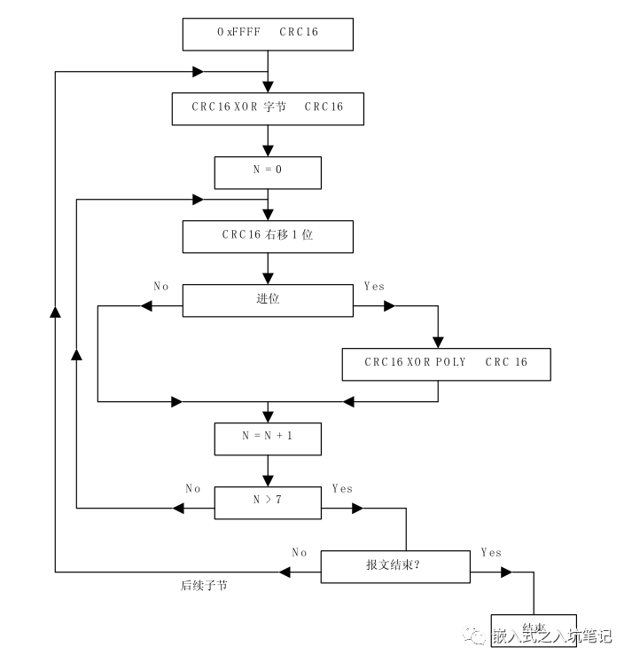
The flowchart is as follows:
(3) Algorithm Implementation for CRC Check GenerationThe calculation of CRC is generally implemented using the lookup table method, which has the advantage of fast calculation speed but the disadvantage of occupying more memory resources. The high byte table of CRC is as follows:
static unsigned char auchCRCHi[] = {
0x00, 0xC1, 0x81, 0x40, 0x01, 0xC0, 0x80, 0x41, 0x01, 0xC0, 0x80, 0x41, 0x00, 0xC1, 0x81,
0x40, 0x01, 0xC0, 0x80, 0x41, 0x00, 0xC1, 0x81, 0x40, 0x00, 0xC1, 0x81, 0x40, 0x01, 0xC0,
0x80, 0x41, 0x01, 0xC0, 0x80, 0x41, 0x00, 0xC1, 0x81, 0x40, 0x00, 0xC1, 0x81, 0x40, 0x01,
0xC0, 0x80, 0x41, 0x00, 0xC1, 0x81, 0x40, 0x01, 0xC0, 0x80, 0x41, 0x01, 0xC0, 0x80, 0x41,
0x00, 0xC1, 0x81, 0x40, 0x01, 0xC0, 0x80, 0x41, 0x00, 0xC1, 0x81, 0x40, 0x00, 0xC1, 0x81,
0x40, 0x01, 0xC0, 0x80, 0x41, 0x00, 0xC1, 0x81, 0x40, 0x01, 0xC0, 0x80, 0x41, 0x01, 0xC0,
0x80, 0x41, 0x00, 0xC1, 0x81, 0x40, 0x00, 0xC1, 0x81, 0x40, 0x01, 0xC0, 0x80, 0x41, 0x01,
0xC0, 0x80, 0x41, 0x00, 0xC1, 0x81, 0x40, 0x01, 0xC0, 0x80, 0x41, 0x00, 0xC1, 0x81, 0x40,
0x00, 0xC1, 0x81, 0x40, 0x01, 0xC0, 0x80, 0x41, 0x01, 0xC0, 0x80, 0x41, 0x00, 0xC1, 0x81,
0x40, 0x00, 0xC1, 0x81, 0x40, 0x01, 0xC0, 0x80, 0x41, 0x00, 0xC1, 0x81, 0x40, 0x01, 0xC0,
0x80, 0x41, 0x01, 0xC0, 0x80, 0x41, 0x00, 0xC1, 0x81, 0x40, 0x00, 0xC1, 0x81, 0x40, 0x01,
0xC0, 0x80, 0x41, 0x01, 0xC0, 0x80, 0x41, 0x00, 0xC1, 0x81, 0x40, 0x01, 0xC0, 0x80, 0x41,
0x00, 0xC1, 0x81, 0x40, 0x00, 0xC1, 0x81, 0x40, 0x01, 0xC0, 0x80, 0x41, 0x00, 0xC1, 0x81,
0x40, 0x01, 0xC0, 0x80, 0x41, 0x01, 0xC0, 0x80, 0x41, 0x00, 0xC1, 0x81, 0x40, 0x01, 0xC0,
0x80, 0x41, 0x00, 0xC1, 0x81, 0x40, 0x00, 0xC1, 0x81, 0x40, 0x01, 0xC0, 0x80, 0x41, 0x01,
0xC0, 0x80, 0x41, 0x00, 0xC1, 0x81, 0x40, 0x00, 0xC1, 0x81, 0x40, 0x01, 0xC0, 0x80, 0x41,
0x00, 0xC1, 0x81, 0x40, 0x01, 0xC0, 0x80, 0x41, 0x01, 0xC0, 0x80, 0x41, 0x00, 0xC1, 0x81,
0x40
} ;
The low byte table of CRC is as follows:
static char auchCRCLo[] = {
0x00, 0xC0, 0xC1, 0x01, 0xC3, 0x03, 0x02, 0xC2, 0xC6, 0x06, 0x07, 0xC7, 0x05, 0xC5, 0xC4,
0x04, 0xCC, 0x0C, 0x0D, 0xCD, 0x0F, 0xCF, 0xCE, 0x0E, 0x0A, 0xCA, 0xCB, 0x0B, 0xC9, 0x09,
0x08, 0xC8, 0xD8, 0x18, 0x19, 0xD9, 0x1B, 0xDB, 0xDA, 0x1A, 0x1E, 0xDE, 0xDF, 0x1F, 0xDD,
0x1D, 0x1C, 0xDC, 0x14, 0xD4, 0xD5, 0x15, 0xD7, 0x17, 0x16, 0xD6, 0xD2, 0x12, 0x13, 0xD3,
0x11, 0xD1, 0xD0, 0x10, 0xF0, 0x30, 0x31, 0xF1, 0x33, 0xF3, 0xF2, 0x32, 0x36, 0xF6, 0xF7,
0x37, 0xF5, 0x35, 0x34, 0xF4, 0x3C, 0xFC, 0xFD, 0x3D, 0xFF, 0x3F, 0x3E, 0xFE, 0xFA, 0x3A,
0x3B, 0xFB, 0x39, 0xF9, 0xF8, 0x38, 0x28, 0xE8, 0xE9, 0x29, 0xEB, 0x2B, 0x2A, 0xEA, 0xEE,
0x2E, 0x2F, 0xEF, 0x2D, 0xED, 0xEC, 0x2C, 0xE4, 0x24, 0x25, 0xE5, 0x27, 0xE7, 0xE6, 0x26,
0x22, 0xE2, 0xE3, 0x23, 0xE1, 0x21, 0x20, 0xE0, 0xA0, 0x60, 0x61, 0xA1, 0x63, 0xA3, 0xA2,
0x62, 0x66, 0xA6, 0xA7, 0x67, 0xA5, 0x65, 0x64, 0xA4, 0x6C, 0xAC, 0xAD, 0x6D, 0xAF, 0x6F,
0x6E, 0xAE, 0xAA, 0x6A, 0x6B, 0xAB, 0x69, 0xA9, 0xA8, 0x68, 0x78, 0xB8, 0xB9, 0x79, 0xBB,
0x7B, 0x7A, 0xBA, 0xBE, 0x7E, 0x7F, 0xBF, 0x7D, 0xBD, 0xBC, 0x7C, 0xB4, 0x74, 0x75, 0xB5,
0x77, 0xB7, 0xB6, 0x76, 0x72, 0xB2, 0xB3, 0x73, 0xB1, 0x71, 0x70, 0xB0, 0x50, 0x90, 0x91,
0x51, 0x93, 0x53, 0x52, 0x92, 0x96, 0x56, 0x57, 0x97, 0x55, 0x95, 0x94, 0x54, 0x9C, 0x5C,
0x5D, 0x9D, 0x5F, 0x9F, 0x9E, 0x5E, 0x5A, 0x9A, 0x9B, 0x5B, 0x99, 0x59, 0x58, 0x98, 0x88,
0x48, 0x49, 0x89, 0x4B, 0x8B, 0x8A, 0x4A, 0x4E, 0x8E, 0x8F, 0x4F, 0x8D, 0x4D, 0x4C, 0x8C,
0x44, 0x84, 0x85, 0x45, 0x87, 0x47, 0x46, 0x86, 0x82, 0x42, 0x43, 0x83, 0x41, 0x81, 0x80,
0x40
};
The generation function of CRC is as follows:
unsigned short CRC16 ( puchMsg, usDataLen ) /* 函数以 unsigned short 类型返回 CRC */
{
    unsigned char *puchMsg ; /* 用于计算 CRC 的报文 */
    unsigned short usDataLen ; /* 报文中的字节数 */
    unsigned char uchCRCHi = 0xFF ; /* CRC 的高字节初始化 */
    unsigned char uchCRCLo = 0xFF ; /* CRC 的低字节初始化 */
    unsigned uIndex ; /* CRC 查询表索引 */

    while (usDataLen--) /* 完成整个报文缓冲区 */
    {
            uIndex = uchCRCLo ^ *puchMsgg++ ; /* 计算 CRC */
            uchCRCLo = uchCRCHi ^ auchCRCHi[uIndex} ;
            uchCRCHi = auchCRCLo[uIndex] ;
    }

    return (uchCRCHi << 8 | uchCRCLo) ;
}
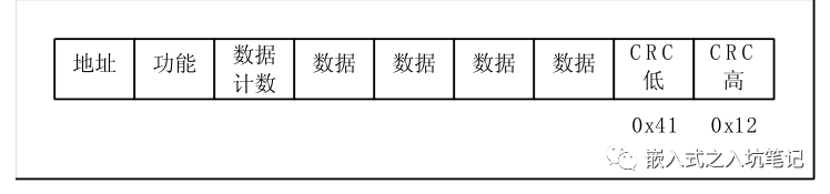
(4) Add CRC checksum to the messageWhen a 16 bit CRC (2 8-bit bytes) is transmitted in a message, the lower byte is sent first, followed by the higher byte. For example, if the CRC value is hexadecimal 1241 (0001 0010 0100 0001), as follows:
2LRC verification in ASCII mode
(1) The generation principle of LRCVertical Redundancy Check (LRC) is a byte containing an 8-bit binary value. LRC is calculated by the sending device and attached to the message. The receiving device calculates LRC when receiving a message and compares the calculated result with the actual value received at LRC. If the two values are not equal, the result is incorrect. The calculation of LRC involves adding up all consecutive 8-bit bytes in the message, ignoring any carry, and then finding their binary complement. LRC is an 8-bit field, so each addition that results in a value greater than 255 simply "wraps" the value of the field around zero. Because there is no 9th digit, the carry is automatically discarded.
(2) The generation process of LRC
1.Excluding the starting point”colon”And end CRLF All bytes in the message are added together into one 8 bit field,Therefore, the carry is discarded。
2.from FF (Full) 1)The final value obtained by subtracting the field from hexadecimal,generate 1 The complement code(Binary Reverse Code)。
3.plus 1 Generate binary complement code.
(3) Algorithm for LRC verification generation
static unsigned char LRC(auchMsg, usDataLen) /* 函数返回 unsigned char 类型的 LRC 结果*/
{
    unsigned char *auchMsg ; /* 要计算 LRC 的报文*/
    unsigned short usDataLen ; /* 报文的字节数 */
    unsigned char uchLRC = 0 ; /* LRC 初始化 */

    while (usDataLen--) /* 完成整个报文缓冲区 */
        uchLRC += *auchMsg++ ; /* 缓冲区字节相加,无进位 */

    return ((unsigned char)(-((char)uchLRC))) ; /* 返回二进制补码 */
}
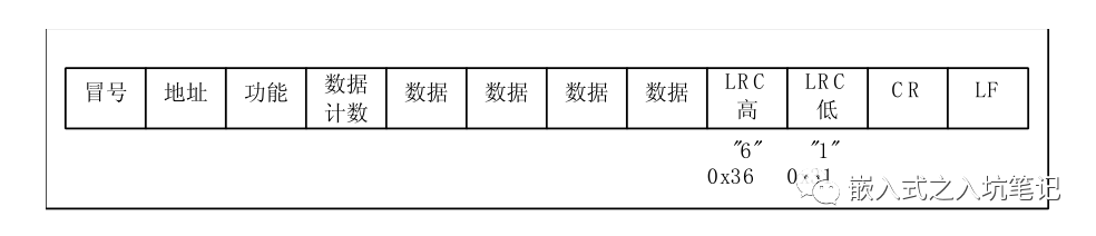
(4) Add LRC checksum to the messageWhen an 8-bit LRC (2 ASCII characters) is transmitted in a message, the high-order characters are sent first, followed by the low order characters. For example, if the LRC value is hexadecimal 61 (0110 0001), as follows:


Leave a Reply