
Since Modbus is a communication protocol, it should have a defined communication format for instruction reception and recognition between devices.
2) Each time the ":" character is received, it indicates the beginning of a new message. If the character is received during the reception of a message, the current message is considered incomplete and discarded. And a new receiving buffer is reallocated.
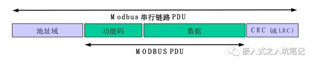
ModbusThe format of the frame on the serial link is as follows:

In the format shown in the figure above:
1) Address Domain: Refers to the address of the child node. The legitimate child node address is 0 – 247. Each sub device is assigned 1 – 247 Address within the scope. The master node addresses the child nodes by placing their addresses in the address field of the message. When the child node returns a response, It places its own address in the address field of the response message to let the master node know which child node is answering.
2) function code: Indicate the actions to be executed by the server.
3) data domain: After the function code, there is data indicating the presence of request and response parameters.
4) Error checking: It is to execute the content of the message "Redundancy check" The calculation results. According to different transmission modes (RTU or ASCII)Using two different calculation methods.
It was explained aboveModbusThe frame format, It is a prescribed protocol for data packaging.
ModbusThere are two serial transmission modes in the system: RTU pattern and ASCII pattern. It defines the content of the message domain for serial transmission over the line. It determines how information is packaged into packets and decoded.
All devices must implement RTU pattern, ASCII Mode is a backup option.
1, Modbus RTUFrame mode
RTUWhat does frame refer to? Simply put, each byte in the message is represented in hexadecimal format.
RTUThe format definition of each byte of data in the frame is as follows:
Each byte is 8bit
Each message in the message 8 Bit bytes contain two 4 Hexadecimal characters(0–9, A–F)

Bits per Byte:
1 start position
8 data bit,First, send the least significant bit
1 Bit as parity check
1 stop bit

note : Use without verification requirements 2 A stop position。
每个字节为8bit报文中每个 8 位字节含有两个 4 位十六进制字符(0–9, A–F)Bits per Byte: 1 起始位8 数据位,首先发送最低有效位1 位作为奇偶校验1 停止位注 : 使用无校验要求 2 个停止位。
The transport stream of characters isLSBSend first, The last one isMSB, as follows:
With parity check:
 Without parity check:

The key is here, RTUThe frame format of the message: 
Modbus RTUThe maximum length of a frame is256bytes.
2, Modbus ASCIIFrame mode
Modbus ASCIIThe frame specifies that each byte of data in the message is divided into twoASCIISend characters.
How do you understand it?
Example : There is a data byte that is 0X5B, It will be encoded as two characters : 0x35 and 0x42 (ASCII coding 0x35 ="5", 0x42 ="B" ).
ASCII Each byte of the pattern section (10 bit ) The format for is :
Each message in the message ASCII Characters contain 1 Hexadecimal characters
Bits per Byte:
1 start position
7 data bit, First, send the least significant bit
1 Bit as parity check
1 stop bit

note : Use without verification requirements 2 A stop position。
报文中每个 ASCII 字符含有 1 个十六进制字符Bits per Byte: 1 起始位7 数据位, 首先发送最低有效位1 位作为奇偶校验1 停止位注 : 使用无校验要求 2 个停止位。
How are characters transmitted serially:
With parity check:
Without parity check:
Modbus ASCIIThe frame format of the message:

ASCIIMessage frames andRTUThe message frames have significant differences, ASCIIThe message frame contains beginning and ending identifiers, This pair of devices is very convenient for receiving message frames. The device can easily know the beginning of a new message frame, And know when the message ends.
RTUThere is no such identifier in the message frame, So when receiving message frames, some processing needs to be done, Only then can we determine whether the message has completed the reception of a frame of data.
ASCIIUse colons in message frames(:)(ASCIIThe hexadecimal system is0x3A)As a starting point, Use carriage return to wrap the line(CR LF)(ASCIIThe hexadecimal system is0x0D 0x0A)by way of conclusion.
Due toASCIIIn mode, each character byte needs to be encoded with two characters, So in order to ensure ASCII pattern and RTU Mode in Modbus Application level compatibility, ASCIIThe maximum data length in the data domain is (2x252) is RTU data domain (252) Twice as much. Therefore, ModbusASCII The maximum size of a frame is 513 One character.
3, RTUFrame andASCIIDifferences in frame transmission
We have already analyzed it earlierRTUMessage frames andASCIIThe difference between message frames, RTUMessage frames do not include start and end identifiersButASCIIThe message frame contains start and end identifiers. So in the device receivingRTUFrame andASCIIThe processing method will be different when it comes to frames.
(1) RTUFrame based message transmission
Now think about a question: RTUBecause there are no start and end identifiers in the frame, How does the device know that it has received a complete frame of message?
In order to confirm that the message has been fully received, Not to perform message parsing and processing upon receiving incomplete messages, So we must find a way to confirm that a frame of message has been received, Then go deal with it.
inRTUIn the mode, To identify different message frames, Insert an idle time interval between message frames, Use at least3.5Using the idle time of one character to distinguish different frames, Simultaneously identify whether a frame has been received or not. This time is also known ast3.5time interval.
This operation method can be understood by looking at the following figure:

If a message frame transmission has started earlier, The receiving device is awakened from an idle state, We need to receive more and implement a timeout mechanism, Used to confirm whether the message frame has been received and completed. As shown in the figure above, if the interval between frame 1 and frame 2 is equal to or exceedst3.5The set idle waiting time, It can be considered that the previous frame 1 has been received completely, The data that comes later belongs to frame 2.
inRTUThere is another important aspect to note in the frame: Because message frames are essentially sent using character streams, To distinguish different message frames, it is necessary to uset3.5The character interval. But how do we confirm that each character in the message frame is continuous?
So in order to confirm the continuous transmission of the character stream, We need to use itt1.5Character time. See the picture below: 
It can be clearly seen from the above picture: If the gap between two characters is greater than 1.5 Character time, The message frame is considered incomplete and should be discarded by the receiving node. Less than or equal to1.5A time of one character is considered normal.
As mentioned abovet1.5andt3.5These two times, Actually, it's not necessarily applicable. Why?
Because in the application of time projects, Many times, the reception of multiple message frames involves interruptions, Especially at high communication speeds, Frequent and rapid interruptions will occurYes, that's rightcpuThe burden is very heavy, At this moment, thist1.5andt3.5The time will become very short, Not very easy to handle.
So, t1.5andt3.5These two times are usually when the communication rate is19200BpsStrict agreement is only required when it is below or below.
(2) ASCIIFrame based message transmission
Due toASCIIMessage frames andRTUMessage frames have significant differences, ASCIIMessage frames have start and end identifiersButRTUThe frame does not have such an identifier. SoASCIIReceiving message frames is much simpler and more convenient, I don't need anything eithert3.5The frame interval time.
But then, To ensure the continuity of the received message frames, It is still possible to agree on the transmission time between characters. It is generally believed, The time interval between characters in the message can reach one second, If this time interval is exceeded, Just assume that an error has occurred, To discard this frame of message data, Restart receiving.
4, RTUFrame andASCIIAnalysis of frame transmission status
(1) RTUTransmission status of frames:

The information that can be obtained from the state diagram above:
1)From "Initial" State to state “free” State transition is required t 3.5 Timed timeout, To ensure inter frame delay.
2) “free” State is a normal state where there are no messages to be sent or received for processing.
3)In RTU pattern, When there is no active transmission time interval 3.5 One character long duration, The communication link is considered to be “free”State.
4) When the link is idle, Any transmitted characters detected on the link are recognized as Frame start. Link becomes "Activity" Status. then, When there is no character transmission on the chain, the time interval reaches t3.5 Afterwards,Identified as End of frame.
5) After detecting the end of the frame, Complete CRC Calculation and verification. then, Analyze the address domain to determine if the frame is being sent to this device, if not, Discard this frame. In order to reduce the receiving and processing time, The address domain can be analyzed immediately upon receipt, And there's no need to wait until the end of the entire frame. like this, CRC The calculation only needs to address the node in the frame (Including broadcast frames) timely conduct.
(2) ASCIITransmission status of frames

The information that can be obtained from the state diagram above:
1) “free” State is a normal state where there are no messages to be sent or received for processing.
2) Every time received ":" Characters represent the beginning of a new message. If the character is received during the reception process of a message, The current message is considered incomplete and discarded. And a new receiving buffer is reallocated.
3) After detecting the end of the frame, Complete LRC Calculation and verification. then, Analyze the address domain to determine if the frame is being sent to this device, if not, Discard this frame. In order to reduce the receiving and processing time, The address domain can be analyzed immediately upon receipt, And there's no need to wait until the end of the entire frame.


Leave a Reply