

Modbus ASCII is a type of message frame in Modbus. Compared to RTU, ASCII transmission is based on character transmission, and the amount of data transmitted will be larger than that of RTU. Therefore, RTU is generally used when the data volume is large, and ASCII is only used when the data volume is small. Then, the ASCII protocol frame adds start and end, and changes the verification algorithm. Below is a detailed introduction to the ASCII protocol
frame format
Modbus ASCII The communication frame format in the mode is as follows:
| Name | Length (byte) | Description |
|---|---|---|
| Start | 1 | Using a colon : beginning, ASCII The hexadecimal value is 3A |
| Address | 2 | Hexadecimal Node Address, Character representation |
| Function | 2 | Hexadecimal function code, Character representation |
| Data | n x 2 | n It is the number of data bytes, It depends on the function code |
| LRC | 2 | LRCRedundancy check code |
| End | 2 | CR / LF |
Note:address, Function, data and LRC All indicate 8 Place value (0-255) Uppercase hexadecimal readable character pairsThat is: in Modbus ASCII In the middle,Each data byte is divided into two representing hexadecimal values ASCII Two bytes of a character.
| Component | Description | character count | ASCIIexpress |
|---|---|---|---|
| Start | Message begins | 1 CHAR | : |
| Address | Node Address (Hexadecimal representation) | 2 CHARS | |
| Function | function code (Hexadecimal representation) | 2 CHARS | |
| Data | data (According to changes in the function code, Hexadecimal representation) | n CHARS | |
| LRC CHECK | Vertical redundancy check code (LRC) | 2 CHARS | |
| END | Message ends, carriage return and line feed | 2 CHARS | CRLF |
in ASCII Under the mode, Modbus Each part of the message appears in a specific number of characters and format, as shown below:
:AA BB CC...DD EE<CRLF>
:- The starting symbol of a message.AA- Node Address, Hexadecimal representation.BB- function code, Hexadecimal representation.CC...DD- data field, Change in length of data to be transmitted based on function code.EE- LRC Verification code, Used for error detection.<CRLF>- End symbol of message, Represents carriage return and line break (Carriage Return Line Feed) .
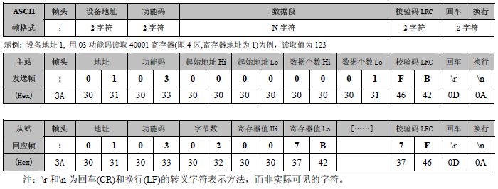
ASCIITransmission status of frames
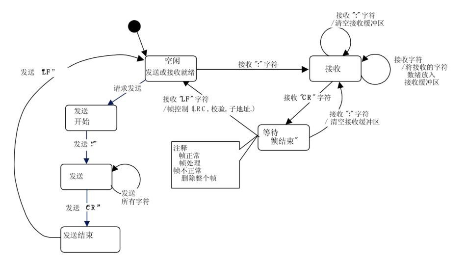
The information that can be obtained from the state diagram above:
1) “free” State is a normal state where there are no messages to be sent or received for processing.
2) Every time received ":" Characters represent the beginning of a new message. If the character is received during the reception process of a message, The current message is considered incomplete and discarded. And a new receiving buffer is reallocated.
3) After detecting the end of the frame, Complete LRC Calculation and verification. then, Analyze the address domain to determine if the frame is being sent to this device, if not, Discard this frame. In order to reduce the receiving and processing time, The address domain can be analyzed immediately upon receipt, And there's no need to wait until the end of the entire frame.
ASCIIFrame based message transmission
Due toASCIIMessage frames andRTUMessage frames have significant differences, ASCIIMessage frames have start and end identifiersButRTUThe frame does not have such an identifier. SoASCIIReceiving message frames is much simpler and more convenient, I don't need anything eithert3.5The frame interval time.
But then, To ensure the continuity of the received message frames, It is still possible to agree on the transmission time between characters. It is generally believed, The time interval between characters in the message can reach one second, If this time interval is exceeded, Just assume that an error has occurred, To discard this frame of message data, Restart receiving.
function code
ASCII The most commonly used functional codes in the mode and RTU The functional code definitions in the mode are the same. Here are some basic function codes and their descriptions:
| Access address | mapped address | Description | Function | R/W |
|---|---|---|---|---|
| 1 ~ 10000 | address-1 | Coils | 01/05/15 | R/W |
| 10001 ~ 20000 | address-10001 | Discrete Inputs | 02 | R |
| 30001 ~ 40000 | address-30001 | Input Registers | 04 | R |
| 40001 ~ 50000 | address-40001 | Holding Registers | 03/06/16 | R/W |
ASCIITransmission Example
for example, To read the address 0x20C1 The two registers, Need to send the following ASCII message:
:010420C1000218<CRLF>
Request:
:- Message begins - 0x3A01- slave address - 0x0104- function code (Read input register) - 0x0420C1- Register address to be read - 0x20C10002- The length of the register to be read (must be 2) - 0x000218- LRC Verification code<CRLF>- Message ends, carriage return and line feed - 0x0D0A
Response:
:01040400001234B1<CRLF>
Response:
:- Message begins - 0x3A01- slave address - 0x0104- function code (Read input register) - 0x0404- Read data length (4 byte) - 0x0400001234- from VAR1 Read value - 0x00001234B1- LRC Verification code<CRLF>- Message ends, carriage return and line feed - 0x0D0A
Common Function Code Operations
Here is Modbus Common function codes and their request and response examples:
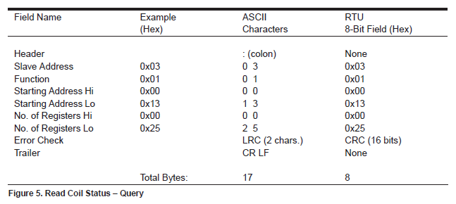
Function 01 (01H) Reading coils
- Request: Read the coil from the slave machine ON/OFF Status.
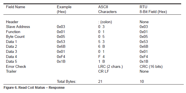
- Response: The coil status response message is packaged into data fields where each bit represents a coil.
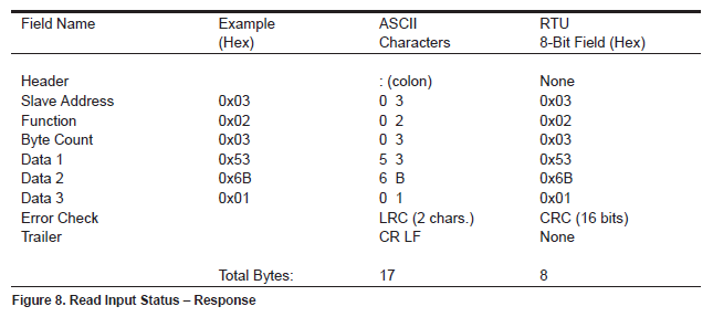
Function 02 (02H) Read discrete input
- Request: Read discrete inputs from the slave machine ON/OFF Status.
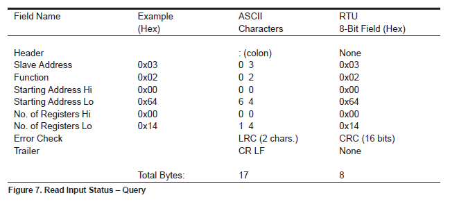
- Response: The construction of discrete input state response messages is the same as that of coil states.
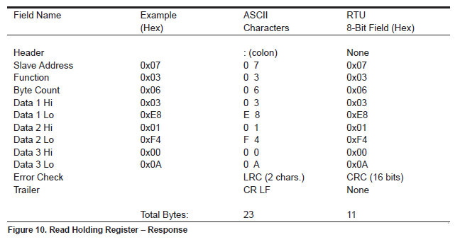
Function 03 (03H) Read and hold register
- Request: Read the binary content of the register held in the slave machine.
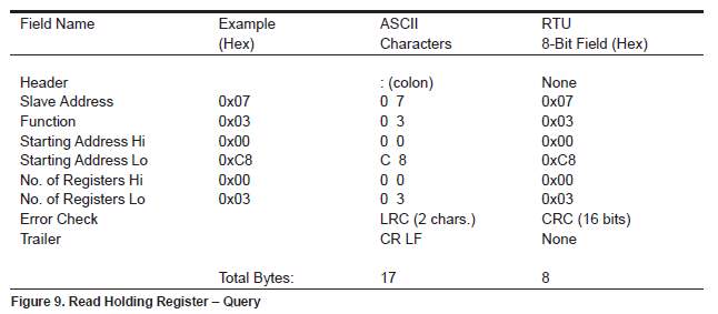
- Response: Keep register data packaged into two bytes in each register.
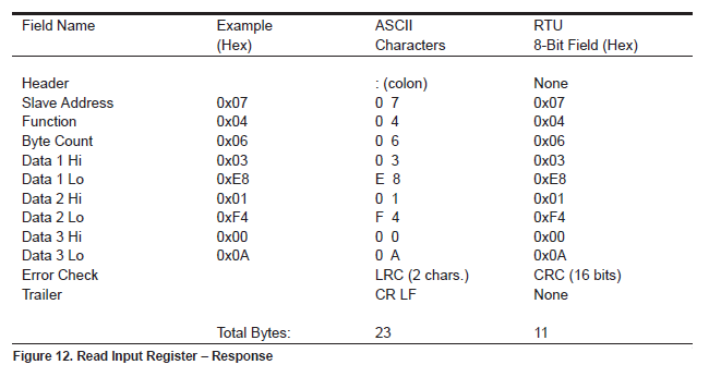
Function 04 (04H) Read input register
- Request: Read the binary content of the input register from the slave machine.
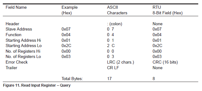
- Response: The construction of response messages for reading input register data is the same as reading hold registers.
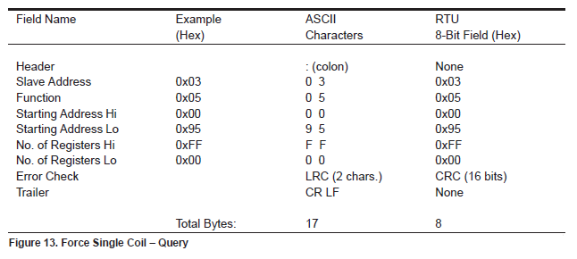
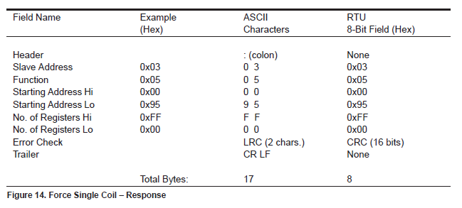
Function 05 (05H) Write a single coil
- Request: Write a single coil into ON or OFF.
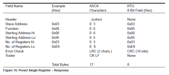
- Response: The normal response is the echo of the request.
Function 06 (06H) Write a single hold register
- Request to write a value into a single hold register. When broadcasting, This function sets the same register reference on all attached slaves. Request message to specify the register reference to be written (Specify address and numerical value) .
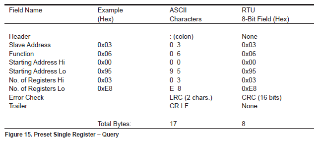
- Response
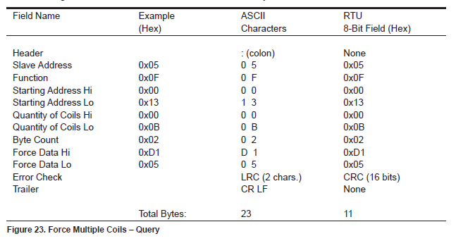
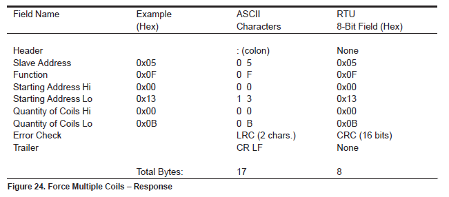
Function 15 (0FH) Write multiple coils
- Request: Write each coil in a coil sequence ON or OFF.
- Response: Normal response returned from address, Function code, Starting address and number of coils written.
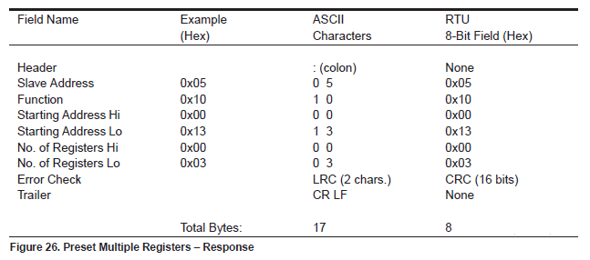
Function 16 (10H) Write multiple hold registers
- Request: Write the value into a hold register sequence.
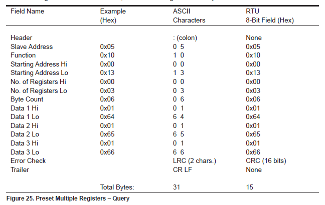
- Response: Normal response returned from address, Function code, Starting address and number of registers written.
LRCVerification
LRC The calculation method of the verification code is as follows:
unsigned char ucMBLRC( unsigned char * pucFrame, unsigned short usLen )
{
    unsigned char ucLRC = 0;  /* LRC char initialized */

    while( usLen-- )
    {
        ucLRC += *pucFrame++;   /* Add buffer byte without carry */
    }

    /* Return twos complement */
    ucLRC = ( UCHAR ) ( -( ( CHAR ) ucLRC ) );
    return ucLRC;
}

Leave a Reply