1. Product Overview
1.1 Purpose
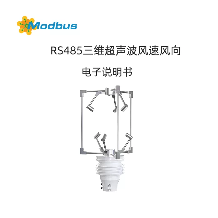
RS-CSFX-N01-3D is a three-dimensional ultrasonic wind speed and direction sensor without mechanical rotating parts, which can measure in real time:
- three-dimensional instantaneous wind speed (X/Y/Z axis)
- synthetic total wind speed
- horizontal wind direction (0~359 °, 0 ° due north)
- vertical wind direction (-90 °~+90 °)
- sound speed and temperature
. It is suitable for fields such as meteorology, oceanography, airports, ports, wind turbines, bridges, tunnels, environmental protection, and scientific research.
1.2 Functional Features
- Zero startup wind speed, 360 ° no dead angle
- No mechanical wear, maintenance free, no on-site calibration
- Metal shell, corrosion-resistant, protection level IP66
- Standard RS-485 interface, Modbus RTU protocol, maximum bus length 2000 m
- Wide voltage power supply 10-30 VDC, maximum power consumption 0.2 W
- Response time 1 s, wind resistance 75 m/s
II. Technical parameters
| Project | Range | Resolution | Accuracy |
|---|---|---|---|
| Synthetic wind speed | 0-60 m/s | 0.01 m/s | ± 0.2 m/s (≤ 5 m/s) or ± 2% FS (>5 m/s) |
| Horizontal wind direction | 0~359° | 0.1° | ±2° |
| Vertical wind direction | -90°~+90° | 0.1° | ±2° |
| speed of sound | 300~370 m/s | 0.01 m/s | ±0.5 % |
| Sound temperature | -40~+70 ℃ | 0.01 ℃ | ±0.5 ℃ |
Working environment: -40~+60 ℃, 0~100% RH
Protection level: IP66
Wind resistance strength: 75 m/s
Output signal: RS-485 (Modbus RTU)
Default baud rate: 4800 bps (can be set to 2400~115200 bps)
Default Address: 0x01
3, Working principle
Using six ultrasonic probes to cyclically emit/receive sound waves in three-dimensional space, calculating the three-dimensional wind speed component through the time difference of forward and backward propagation, and then vector synthesizing the total wind speed and wind direction. Without mechanical rotating parts, it belongs to "inertial" measurement and can truly capture gust pulsation.
4, Product selection
RS- CFSFX- N01- 3D
① ② ③ ④
① Company Code
② Ultrasonic wind speed and direction series
③ 485 communication (Modbus RTU)
④ Three dimensional shell
5, Mechanical dimensions and installation
5.1 Overall dimensions
Height 268 mm x Width 482 mm (see manual illustration)
Installation column: Ø 50~60 mm round pole or equivalent rectangular pole
5.2 Installation steps
- Insert the sensor into the upright pole so that the arrow "N" on the housing is facing due north.
- Use a wrench to tighten the four stainless steel bolts at the bottom, ensuring that the equipment is level and not tilted.
- Recommended installation height: 1.5-10 meters above the ground (according to application standards).
- Carry out lightning protection, grounding, and waterproof treatment.
5.3 Wiring Definition (5-core sheathed wire, default wire length 3 m)
| Wire Color | Definition | Remarks |
|---|---|---|
| Brown | Power Supply Positive | 10~30 VDC |
| black | power ground | GND |
| green | 485-A | Connect host 485-A |
| blue | 485-B | Connect to host 485-B |
| shielded layer | earth | Connecting to the chassis/lightning protection ground |
5.4 Bus Requirements
- Hand in hand wiring to avoid star shaped wiring
- Add a 120 Ω terminal resistor at the beginning and end
- When the length is greater than 500 meters, add a 485 repeater at 1/3 of the bus
- Multiple devices must be set to different addresses
6, Configure software usage
6.1 Software Acquisition
Package → "Debugging Software" → "485 Parameter Configuration Software" → No installation required, run directly.
6.2 Quick Configuration
- Use a USB → 485 converter to connect the sensor to the computer.
- Open the software and select the corresponding COM port. Click on "Test Baud Rate" and the software will automatically recognize the address and baud rate.
- Click on 'Test Baud Rate', and the software will automatically recognize the address and baud rate.
- Modify the address (1~247) and baud rate (2400~115200) → Click "Send".
- Switch to the "Real time Data" page to view/save/curve display all variables.
- Advanced parameters: output mode, average time, rationality check, X/Y/Z axis coefficients, etc., can be read and written on this page.
7. Modbus RTU Communication Protocol
7.1 Serial Port Parameters
8N1, No Verification, CRC16, Default 4800bps
7.2 Data Frame Format
Host Inquiry: Address Function Code Register Starting Address Register Number CRC Low CRC High
Slave Response: Address Function Code Byte Number Data Area... CRC Low CRC High
7.3 Register Overview (hexadecimal)
| Register Address | Content | Type | Read/Write |
|---|---|---|---|
| 0000~0001H | Synthetic Total Wind Speed | Float | R |
| 0002~0003H | Horizontal Wind Direction | UINT16 | R |
| 0004~0005H | Vertical Wind Direction | INT16 | R |
| 0006~0007H | X-axis Wind Speed | Float | R |
| 0008~0009H | Y-axis wind speed | Float | R |
| 000A~000BH | Z-axis wind speed | Float | R |
| 000C~000DH | Sound temperature | Float | R |
| 000E~000FH | Sound speed | Float | R |
| 0010H | Output mode | UIN16 | R/W |
| 0011H | Average time | UIN16 | R/W |
| 0012H | Rationality test | UIN16 | R/W |
| 0013H | Wind force level | UIN16 | R |
| 0014~0017H | X/Y/Z/total maximum wind speed | UIN16 | R |
| 0020~002BH | X/Y/Z axis coefficient A/B | Float | R/W |
| 07D0H | Modbus Address | UINT8 | R/W |
| 07D1H | Baud Rate Code | UINT8 | R/W |
| 07D5H | Software Version | UINT16 | R |
| 07D6H | Hardware Version | UINT16 | R |
7.4 Reading Example (Read 0x01 Address to Synthesize Wind Speed)
Host Sent: 01 03 00 00 02 85 CA
Slave Returned: 01 03 04 41 70 28 F6 71 92
Analysis: 41 70 28 F6 → Float ≈ 15.01 m/s
8. Common Problems and Troubleshooting
| Phenomenon | Possible Causes | Solution |
|---|---|---|
| Computer Cannot Find Device | COM Port Error/Driver Not Installed | Confirm COM Number in "Device Manager" and Reinstall Driver |
| Communication Failure | Address and Baud Rate Error | Search again with "Test Baud Rate" |
| All data is 0 | Reverse wiring/insufficient power supply | Test power supply voltage ≥ 12V, check if 485-A/B is reversed |
| Data jump is huge | Rationality check | Turn off or increase average time |
| Long distance no communication | No terminal resistance/fine wire diameter | Add 120 Ω at the beginning and end, use twisted pair shielded wire of 0.5 mm ² or more |
9. Maintenance
- Wipe the surface of the shell with clean water or neutral detergent every 6 months, and do not use acidic/alkaline solvents.
- Check if the cable sheath and joint waterproof gasket are aging, and if necessary, re wrap the waterproof tape. After encountering typhoons or hail, visually inspect the probe for cracks and immediately stop the machine for replacement if any damage is found.
- After encountering typhoons or hail, visually inspect the probe for cracks and immediately stop the machine for replacement if any damage is found.
- If it is not in use for a long time, please turn off the power and remove it and store it in a dry warehouse.
10. Packaging List
- RS-CSFX-N01-3D Host x 1
- Certificate of Conformity/Warranty Card x 1
- Installation Clamp and Bolt Kit x 1 Set
- 3m Cable (default length) x 1
- USB → 485 Converter (optional) x 1
11. Warranty and After sales
- The whole machine is guaranteed for 12 months, based on the date on the factory label.
- Human damage, lightning strikes, water ingress, and unauthorized disassembly are not covered by the warranty.
- Please attach a fault description and contact information for repair. The shipping cost for returning the item will be borne by the user, while the shipping cost for sending it out will be borne by the manufacturer.


Leave a Reply