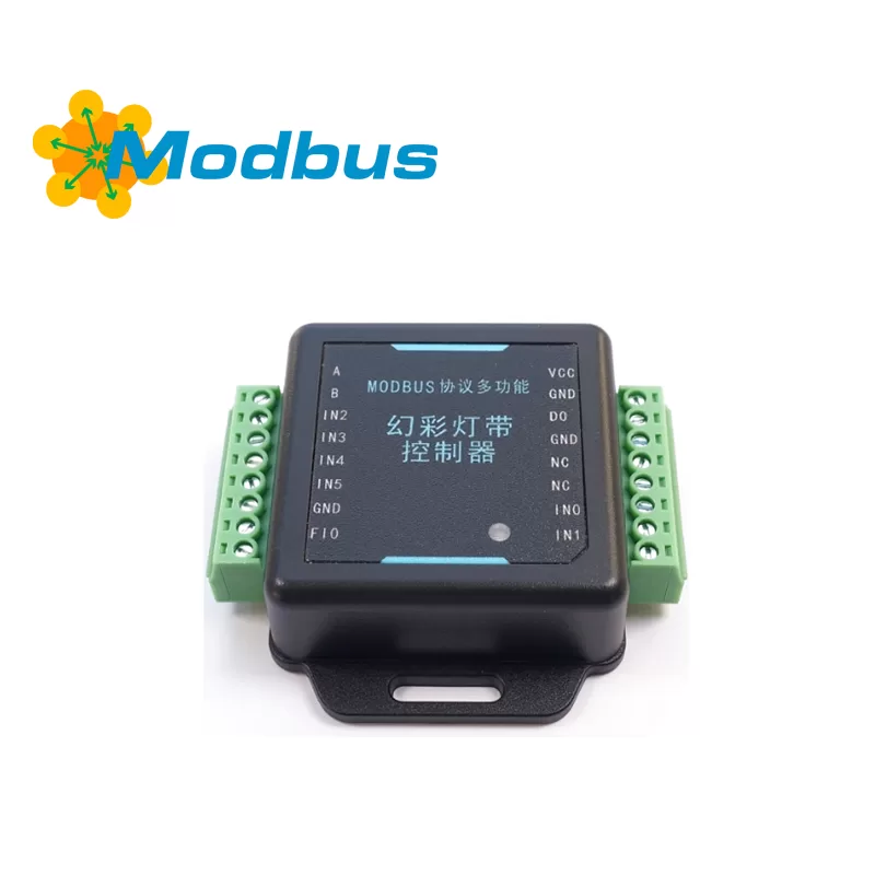
1. Product Introduction
This controller adopts the standard Modbus RTU protocol (RS-485), with 24 commonly used lighting modes built-in, supporting effects such as monochrome, gradient, flowing, breathing, flashing, and multi frame playback. It can be controlled in real-time through serial port or external IO, and can also run offline. Users do not need to write code, they only need to modify register parameters to achieve the desired animation. The controller supports a wide voltage supply of 5 V to 24 V, with a maximum controllable capacity of 1200 LED beads (based on a 5 V single point), and is compatible with mainstream single wire zero code ICs on the market.
2. Technical parameters
| project | Specification |
|---|---|
| Operating Voltage | 5 V to 24 V ± 5% |
| Power Consumption | < 1 W |
| Communication Interface | RS-485 (A/B) |
| Default Baud Rate | 9600 bps (4800~460800 optional) |
| Data format | 8N1 (parity can be set) |
| Controllable point count | ≤ 1200 points (5 V single point) |
| LED strip port | 1-channel data output (DO) |
| Switching input | 6-channel (IN0~IN5, low level effective) |
| Frequency input | 1-channel (FI0, 1 Hz~10 kHz) |
| Operating temperature | –25 ℃~+75 ℃ |
| Storage temperature | –40 ℃~+85 ℃ |
| relative humidity | < 75 % RH |
| Overall dimensions | 68.5 mm × 66.4 mm × 20 mm |
3. Interface definition
3.1 Power/Signal Terminal (Right Side)
| terminal | Explanation |
|---|---|
| VCC | Positive power supply (5 V~24 V) |
| GND | Power ground (shared with the light strip) |
| DO | Data output (connected to DIN light strip) |
| NC | empty foot |
| IN0~IN5 | Switch input (triggered by ground closure) |
| FI0 | Frequency signal input (ground pulse) |
3.2 Communication terminal (left side)
| terminal | Explanation |
|---|---|
| A | RS-485 A |
| B | RS-485 B |
| GND | Communication location (optional) |
4. Support light strip types
By selecting the IC model through register 2000, the following protocols are built-in:
WS2812B / WS2811 / WS2813 / WS2815 / WS2818 / SK6812 / UCS1903 / TM1903 / FW1903 / FW1935 / TM1934 / SM16703 / MT1815 And customize the pulse width mode.
(If using 12V or 24V LED strips, please confirm the number of LED beads carried by one IC and fill in the "LED strip count" parameter according to the number of ICs.). )
5. Quick wiring diagram
交流市电 → 开关电源(5 V/12 V/24 V) → 控制器 VCC/GND
控制器 DO → 灯带 DIN
控制器 GND → 灯带 GND(必须共地)
RS-485 转换器 A/B → 控制器 A/B
USB-485 转换器 → PC
Note that
- The light has a direction, and the DIN must be connected to the controller DO.
- For long-distance power supply, please connect a set of power lines every 2 meters to avoid voltage drop.
- The communication line adopts twisted pair shielded wire, and the shielding layer is grounded at one end. If the controller and light strip use independent power supply, they need to be connected.
- If the controller and the light strip use independent power sources, they need to be connected to each other.
6. Status indicator light
| Indicator light | Meaning | Processing |
|---|---|---|
| Green light flashes at 0.5 Hz | Normal operation | — |
| Green light breathing | Pause | — |
| Green light flashes at 0.25 Hz | Stop | — |
| Red light flashes at 1 Hz | Parameter error or Flash fault | Power off and restart, reconfigure |
| Yellow light flashes 3 times in a row | Modbus parameter exceeds limit | Check register range |
| Yellow light flashes 6 times in a row | Restoring to factory | Do not power off within 2 minutes |
7. Register overview (Modbus address table)
All addresses are decimal (PLC base address=1), please subtract 1 when issuing from the main machine.
| Function Area | Address Range | Description |
|---|---|---|
| Device Parameters | 1000-1014 | Address, baud rate, power on behavior, etc. |
| Light strip parameters | 2000-2009 | IC type, RGB order, pulse width |
| Coil trigger | 1000-1014 | Start/Pause/Stop/Turn off, etc. |
| Discrete input | 1000-1015 | Running status, IO level |
| Input register | 1000-1019 | Version, current effect, error code |
| Mode configuration | 2100-2149 | 24 template parameters |
| Program storage | 2200-2229 | 128 program slots |
| List configuration | 4000-4059 | 6-class list (loop/parallel/trigger) |
| BUF data | 5001-9800 | 1200 dots x 4 bytes RGBW |
| Hardware interface | 3000-3269 | IO function mapping |
| Flash operation | 4900-4915 | 2 MB image storage |
| Brightness control | 2400-2410 | Real time brightness overlay |
8. Common mode quick check
| Mode number | Effect | Key parameter examples |
|---|---|---|
| 1004 | Overall monochrome | 2125~2128 Setting RGBW |
| 1014 | Dual color gradient cycle | 2125/2129 Color 1/22133 Steps |
| 1015 | Tri color gradient cycle | 2125~2136 Three segment colors |
| 1017 | Breathing light | 2125 Color, 2130/2131 Steps |
| 1013 | BUF Flow | Starting from 2129, 2130 length |
| 1022 | BUF multi frame playback | Starting from 2125, 2126 frames per second |
| 1023 | Flash multi frame playback | 2125~2127 Image addresses |
9. Typical configuration process (taking "overall red gradient to blue" as an example)
- Power on, connect to PC, open debugging software, select serial port, and click "Connect".
- [Lamp strip parameters] Select IC type and RGB order.
- [Mode Information] Address 2100 is written as 1014 (dual color gradient).
- Double click 2125/2129 to bring up the color picker, and set red (255, 0, 0) and blue (0, 0, 255) respectively.
- Address 2133 is written as 100 (gradient steps).
- [Program Information] Write 2000 to address 2200. After confirming 2202=1, write 1 to address 2228 and save it as program 2000.
- Disconnect the serial port, power on again, and the light strip will automatically run this effect.
10. External IO Control (Example)
Objective: Press the button once to switch the light strip between "Red → Blue Gradient" and "Green Breath".
Step:
- 【 Hardware Interface 】 Turn on the main switch 3000=13010=1.
- IN0 is mapped to the [Program] area, with address 3020=33022=22003023=3 (falling edge count).
- Save 3025/3026 with 0/13027=13004=1.
- Store two programs: 2000=Red Blue Gradient, 2001=Green Breath.
- Add 2000 and 2001 to playlist 3060 and set 4007=2.
- Each time the button is pressed, the list order switches, achieving a rotation of two effects.
11. Real time brightness adjustment
- Address 2400=1 to enable brightness control.
- Address 2406=50 Current brightness 50% (0 off, 100 original brightness,>100 brightness increase).
- The "+/-" button can be triggered through 2409/2410, or it can be changed in real-time through IO/frequency mapping.
Attention: Brightness adjustment will reduce the frame rate. It is recommended to return to the mode parameters to solidify the brightness after the final effect is determined.
12. Flash image upload (special requirements only)
- Stop light effect, 4912=1 Enable Flash operation.
- 4910/4911 Set the starting page (must be a multiple of 4096).
- Convert BMP to RGBW by "loading image to BUF", fill 4096 bytes, and write 4914=1.
- Repeat until all images are completed and 4912=2 is closed. When calling mode 1023, simply fill in the total frame count, starting address, and running direction.
- When calling mode 1023, simply fill in the total frame rate, starting address, and running direction.
13. Troubleshooting
| Phenomenon | Possible causes | Solution |
|---|---|---|
| No response when powered on | Power supply reverse connection/voltage mismatch | Check polarity and voltage |
| Communication failure | Address/baud rate error, AB reverse connection | Power off and power on again to check serial port prompt |
| Light strip flickering | Poor ground connection, long wire | Shorten signal wire, add 100 Ω resistors at both ends |
| Effect not saved | Storage trigger not executed | 2228/4057/4914 Write 1 |
| Overlapping area flower screen | Parallel list area overlap | Starting position and length of each program staggered |
14. Safety and maintenance
- Confirm voltage matching before powering on, reverse connection will burn out the equipment.
- Do not plug or unplug screw terminals when live to avoid spark damage to the contacts.
- Check the tightness of the terminals and remove dust every month.
- If not in use for a long time, please store it with power off to avoid moisture.
15. Packing List
- Controller x 1
- Pluggable terminals x 3
- Instruction manual x 1
16. Liability statement
Damage caused by wiring errors, overvoltage, or unauthorized modifications is not covered by warranty; The images and data uploaded by users themselves must ensure that the copyright is legal.


Leave a Reply