
Design requirements for a perfect PLC program
A complete PLC program is not just about making the system run; it also requires comprehensive annotations, a well-designed architecture, good scalability, a complete alarm protection system, and a simulation system before operation.
1. Simplicity
Make the PLC program as simple as possible. Simplicity means using standardized program frameworks and simple instructions as much as possible.
To make the program simple, from a broader perspective, it is necessary to optimize the program structure, simplify the program using flow control instructions, and from a more specific perspective, replace instructions with single functions with instructions with multiple functions, and pay attention to the order of instructions.
2. Readability
The designed program should have good readability. This not only facilitates the programmer's understanding of the program and debugging, but also makes it easier for others to understand the program and for users to maintain it. When necessary, it can also promote the program.
To make the program readable, the designed program should be as clear as possible. Attention should be paid to hierarchy, modularization, and even object-oriented design. Standard designs should be used more often.
In special cases where language programming is used, ladder diagram programming should be used in most cases for ease of reading.
Additionally, I/O allocation should be regular to facilitate memory and understanding. When necessary, some annotations should be made. The use of internal components should also follow a certain pattern, rather than being used randomly.
Readability should be considered from the beginning of program design. It is not easy to achieve completely, as during program debugging, the addition or removal of instructions and changes in the use of internal components may make the originally clear program somewhat messy. Therefore, some leeway should be left for debugging during design, and the program should be organized after debugging to ensure higher quality.
The annotations of the program should at least include the following aspects:
A. System annotation: The copyright company of the entire program and the purpose of this program
B. Program block annotation: The main purpose and author of this program block
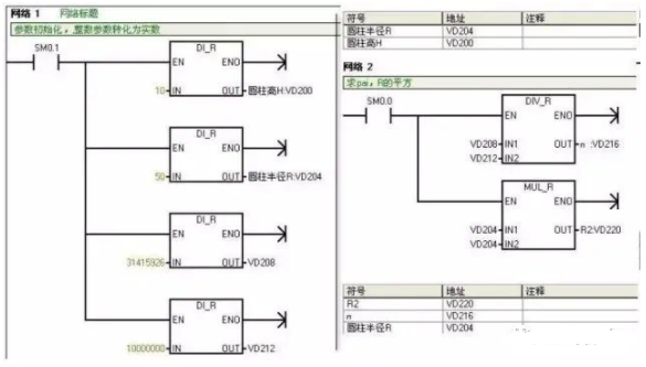
C. Segment annotation: The purpose of this code segment
D. Variable annotation: The importance goes without saying, including I/O annotations and intermediate variable annotations
As for confidentiality considerations, I think we should consider encryption algorithms for the program or its blocks, rather than resorting to the unwise practice of reducing annotations.
3. Correctness
PLC programs must be correct and undergo practical verification to prove their ability to work correctly. This is the fundamental requirement for PLC programs. If this cannot be achieved, the rest is useless no matter how good it is.
To ensure program correctness, instructions must be used accurately, and internal components must be used correctly. Accurate use of instructions is linked to accurate understanding of instructions, so it is essential to clarify the meaning and usage conditions of instructions. When necessary, small programs can be written to test some unclear instructions.
Due to different factory batches or series models of PLCs, some instruction details may vary. Therefore, it is important to carefully consult the programming manual.
The correct use of internal components is also important. For example, some PLCs have power-down protection, while others do not. It is necessary to ensure that components with power-down protection are used where appropriate, and vice versa.
In summary, accurate use of instructions and correct use of internal components to ensure the correctness of the programmed program are the fundamental requirements for PLC programs.
Let me give a simple example. Siemens requires the use of variables with storage functions as intermediate variables for rising and falling edges, such as M points or DB points. Using FC's temp variables will cause problems.
4. Reliability
Programs should not only be correct but also reliable. Reliability reflects the stability of PLC programs, which is also a basic requirement for PLC programs.
Some PLC programs can work correctly under normal working conditions or legal operations, but when abnormal working conditions occur (such as temporary power outages followed by quick re-energization) or illegal operations are performed (such as pressing buttons out of sequence or pressing multiple buttons simultaneously), the program cannot work properly. Such programs are not very reliable, or unstable, and are considered poor programs.
Good PLC programs can recognize abnormal working conditions and seamlessly transition them to normal conditions, allowing the program to adapt to various situations. Good PLC programs can reject illegal operations without leaving any "traces" and only accept legal operations.
Interlocking is a common means of rejecting illegal operations, often used in relay circuits, and PLCs can inherit this method.
5. Easily Modifiable
To make a program easily modifiable, it means to facilitate modification. One of the characteristics of PLCs is their convenience and flexibility in adapting to various situations. The approach is to rely on modifying or redesigning the program.
Redesigning a program to change the usage requirements of PLC technology not only requires program recompilation but also I/O reassignment. In most cases, reprogramming is not necessary; some modifications are sufficient. This requires the program to be easily modifiable.
Easily modifiable also means flexibility, requiring minimal changes to achieve the purpose of changing parameters or modifying actions.
6. Scalability
Many programs may have been pre-programmed before entering the field, but additional programs may still need to be added on-site. To avoid disrupting the structure of the entire system, a certain amount of space needs to be reserved in each functional area for backup.
Sufficient margin should be left on the hardware, and manual, automatic, and semi-automatic considerations should be made during software programming, with positions reserved.
7. Complete Alarm System
PLC systems are often used in industrial environments, where each accident can cause significant or minor losses. To achieve accident pre-treatment or minimize losses during an accident, it is essential to pay attention to the alarm and protection of the PLC. Therefore, it is highlighted as an important component of the system.
8. Program Simulation
To ensure on-site debugging progress or to demonstrate to customers, it is often necessary to perform a fully automated simulation of the program before entering the site. To achieve this, a simulation program section needs to be added to the program, which is disconnected after normal on-site operation. To enable the program to have simulation functionality, the following work needs to be done:
(1) Convert the actual PLC I/O points to PLC intermediate variables or data block variables;
(2) Write simulation programs for each device according to process requirements. In the process of designing PLC programs, a good program can be considered as one that meets the requirements mentioned above.
II.PLC Programming Specifications
1. Select the appropriate PLC model and I/O point count, and choose special function modules when there are special functional requirements.
2. Familiarize yourself with the selected PLC programming instructions and compilation software.
3. Plan soft components, including internal relays, holding relays, data registers, timers, counters, etc.
4. Plan the program, generally following the sequence of fault extraction, fault handling, manual handling, automatic handling, and output handling. For larger projects or equipment, segment and block processing according to functional units, such as an automated production line with elevators, moving devices, and lifting and rotating devices, which should be programmed according to the above-mentioned units.
5. Before writing segmented and blocked programs, brief segment comments should be added to explain the function of each program segment. If necessary, the corresponding process flow can be indicated. The order of the blocked or segmented programs in the overall program should be arranged basically in accordance with the process flow sequence, facilitating program readability.
6. Before programming, the equipment should be abstracted, and common factors such as stop, emergency stop, overload, overrun, timeout, safety light curtains, touch stop, door switches, etc., should be extracted and placed in the startup circuit or startup master control and interlock circuit, serving as the major premise for the entire program structure. Based on this, the program can be divided into two major functional areas: automatic and manual.
7. Extract common factors in the manual functional area of the program structure, such as manual operation and factors endangering equipment and personal safety, and place them in the manual master control and interlock circuit to protect, shield, and alarm manual control.
8. Extract common factors in the automatic functional area of the program structure, such as automation, overrun, timeout, etc., and place them in the automatic master control and interlock circuit to protect, shield, and alarm equipment under automatic control. The general principle is to strictly limit equipment input and loosely restrict equipment output under the premise of ensuring safety.
9. During program design, a total reset function should be designed to facilitate users in quickly restoring normal operation of the equipment in case of equipment failure. The total reset should fully consider the safety of equipment and personnel during the reset process.
10. When switching from automatic mode to manual mode, the program should clear the output and intermediate states in automatic mode. Especially when using the SET instruction in automatic mode, it must be cleared using the RESET instruction in manual mode.
11. It is strictly prohibited to use dual output in programming, that is, the same output statement or the same output coil appearing twice or more in the program. Under different mode conditions, intermediate relays should be used to transfer the output to the same output point, and finally, they should be combined and connected to the output point.
12. When using a touch screen, the control and status areas shared by the touch screen and PLC should not be used for programming of other functions.
13. Before using special modules of PLC, it is necessary to check whether their control and status areas occupy working words. If they do, these working words should not be used for programming in other aspects.
14. Chinese annotations should be added to PLC inputs, outputs, intermediate relays, timers, counters, data registers, etc. Inputs and outputs should also have component name tags. For corresponding input points, the default is that the peripheral switch connects to a NO contact. If an NC contact is required, it must be indicated in the annotation. All annotations should be clear and unambiguous, avoiding generalizations as much as possible.
After the engineering debugging is completed, the final software program must be retained by the system, and the saved file name should include project number/author/date information/version number, etc.
16. Regarding program encryption: The password for encrypted programs must be saved in a dedicated file, specifying the corresponding username + password + permissions. This file should be distributed to at least two individuals who are aware of the password, to prevent the situation where the password is lost and the program cannot be opened.
III.Programming Suggestions
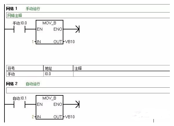
1. When a PLC and a host computer (or touch screen) form a monitoring system, control modes such as "Manual" and "Auto" are often required on the interface (usually only one mode can be selected from multiple options). In the program, the "MOV" instruction can be used. For example, when "Manual" is selected, the constant 1 is MOVed to a register VB10; when "Auto" is selected, 2 is MOVed to the same register VB10. By simply checking the data in the register, you can determine which control mode the system is in. This approach has the advantage of being easy to understand and eliminating the need for complex programs such as interlocking.
2. When the program involves analog control, if the readings of the analog quantity have little error, a time-based filtering method can be adopted, delaying the output for a certain period of time. If the readings have significant errors, other filtering methods such as calculating the average value should be used. Relevant information can be consulted.
3. During program debugging (especially when the program is integrated into an existing device), if the output coil does not turn on when the condition in the program statement is met, you can check whether the problematic statement is between JUMP or go to statements. Another possibility is that the condition is met after an interrupt, but the output does not turn on because the program is not being scanned.
4. In sequential control programs, where one action is completed before proceeding to the next, using a +10+10 control mode is very convenient. The idea is to preset a register with a value of 0 during initialization. After the system starts, increment the register by 10, making it 10. When the register equals 10, the first action can be executed; after the first action is completed, increment the register by 10 again, making it 20, and the second action can be executed. After the second action is completed, increment the register by 10 again, making it 30. In this way, by simply checking the data in the register, you can determine which action to complete. When a skip action is required, you can stop incrementing by 10 and increment by 20, 30, etc., depending on actual needs. The reason for incrementing by 10 instead of 1 is that if a skip is inserted, you can simply choose any of the 10 empty spaces.
5. When designing a program, in case of process failures (not controlled by the control system), it is best to maintain the fault phenomenon and provide visual and audible alarms until the operator resets it, so that they know the system has encountered a fault. Otherwise, if the machine stops, others may think it's a problem with the program. Generally, these considerations should be taken into account when designing a new system.
6. For frequently invoked subprograms, they can be made into submodules for repeated use.
7. Since the movements of production machinery in various steps of the work cycle require a certain amount of time to execute, and these times have certain limits, these times can be used as a reference. At the same time as the start of the step action to be detected, a timer is started, and the time setting value of the timer is 20% to 30% longer than the duration of the action under normal conditions. The output signal of the timer can be used for alarm or automatic shutdown devices. When the time for a certain step action of the production machinery exceeds the specified time and reaches the corresponding timer preset time, and the next step action has not yet been shifted to, the timer sends out a fault signal, which stops the normal work cycle program and starts the alarm or shutdown program. This is what we often refer to as over-cycle protection.
8. Some safety detection switches (such as emergency stop buttons, safety light curtains, limit switches, etc.) utilize normally closed (NC) inputs.
9. For safety and energy conservation, the output should be designed to activate only when necessary, and to cease once it reaches its intended position, rather than being continuously outputted during normal times and only disconnected when required to stop.
10. The principle for the action of actuators should be: better not to move, than to move randomly!
11. Single device control: Each individual device must have a soft manual operation/automatic switching function, as well as the ability to start/stop during soft manual operation. When switching from automatic to soft manual operation, the device cannot be stopped; when switching from soft manual operation to automatic, the device's start/stop depends on the automatic program.
12. Single device (pumps, fans, and other large equipment) running for 24 hours


Leave a Reply